I needed to change a lot to the javascript on the website to fix some stuff.
Fix IPhone control. (I hate iphone)
Fix screenlock timeout
Added meta refresh
The XMAS/Fireworks controller was often used, and I got notifications via my TV. (see other posts)
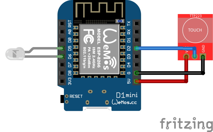
Now I want to see when MQTT movement when I’m in the livingroom. So I programmed a Wemos controller to blink the internal when MQTT messages are received.
CODE:
#include <ESP8266WiFi.h>
#include <PubSubClient.h>

const char* ssid = "WIFIAP";
const char* password = "WIFIPASS";

const char* mqtt_server = "MQTTBROKER";  // MQTT broker IP
const char* mqtt_topic  = "game/tilt";

WiFiClient espClient;
PubSubClient client(espClient);

String lastPayload = "";

void setup_wifi() {
  delay(10);
  WiFi.begin(ssid, password);
  while (WiFi.status() != WL_CONNECTED) {
    delay(500);
  }
}

void blinkLED() {
    digitalWrite(LED_BUILTIN, LOW);   // LED ON
    delay(200);
    digitalWrite(LED_BUILTIN, HIGH);  // LED OFF
    delay(200);
}

void callback(char* topic, byte* payload, unsigned int length) {
  String message;
  for (unsigned int i = 0; i < length; i++) {
    message += (char)payload[i];
  }

  // Blink only if topic value changed
  if (message != lastPayload) {
    blinkLED();
    lastPayload = message;
  }
}

void reconnect() {
  while (!client.connected()) {
    if (client.connect("WemosClientMqttBlink")) {
      client.subscribe(mqtt_topic);
    } else {
      delay(2000);
    }
  }
}

void setup() {
  pinMode(LED_BUILTIN, OUTPUT);
  digitalWrite(LED_BUILTIN, HIGH);

  setup_wifi();

  client.setServer(mqtt_server, 1883);
  client.setCallback(callback);
}

void loop() {
  if (!client.connected()) {
    reconnect();
  }
  client.loop();
}
Another game in the making is a Red Light – Green Light game. Like in Squid Game. This will use a lidar and a python script which detect movement using a camera.
While this is a old project from 2019, I decided to make a more responsive one, after my friend Tyrone mentioned a project somewhere on the internet (forgot where). Time to dust off this project!
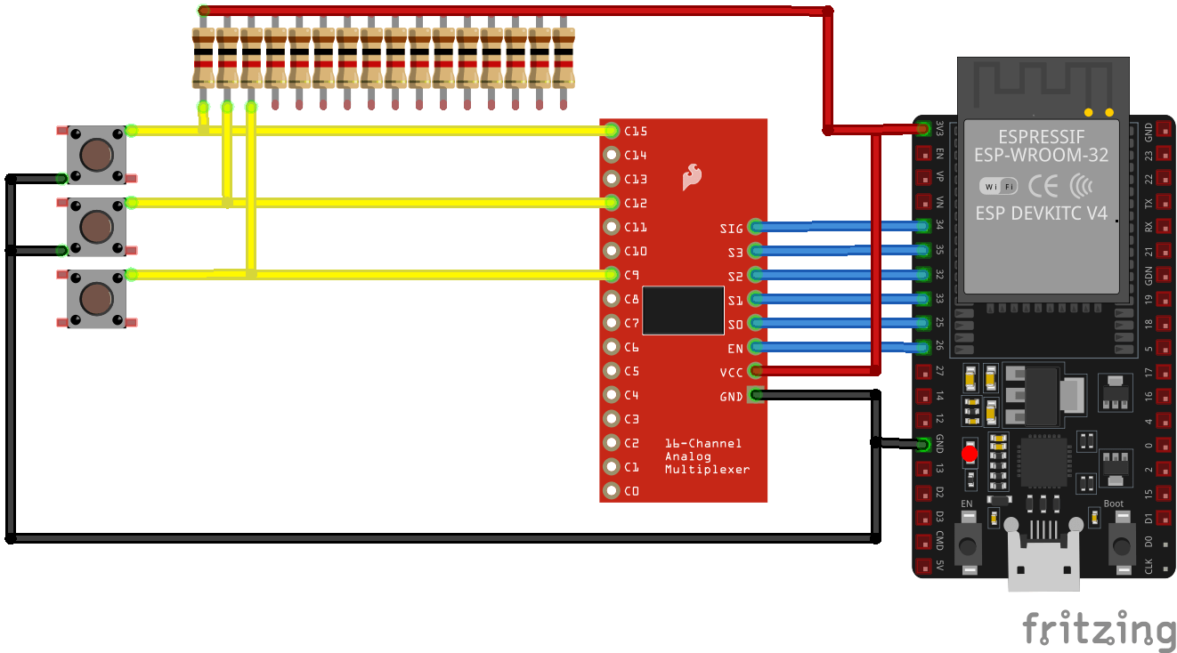
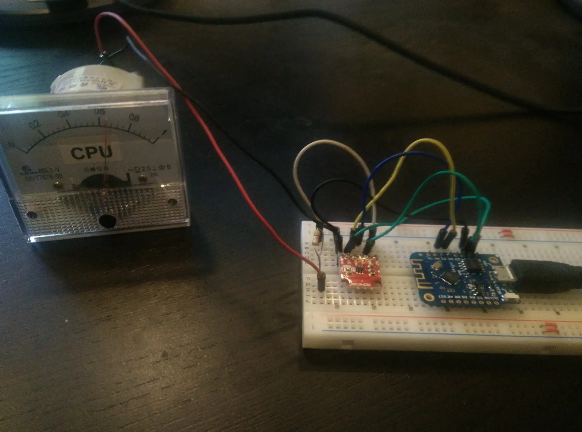
2019 version
Above version worked but was slow. I used a python script to send values to de controller.
Memory setup was the same.
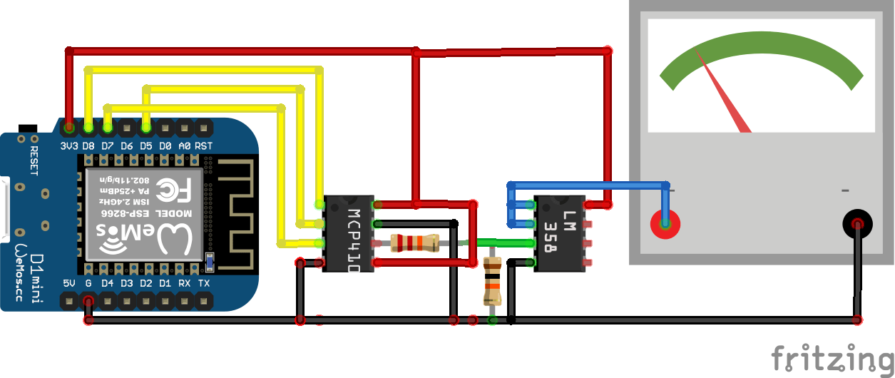
Below my new schematic, using an opamp to drive the analog meter.
Untested design .. Yeah I got bored on new year’s eve
Utilizing a MCP41000 digital potmeter and a LM358 signal amplifier I hope to get a more responsive setup.
We are planning to redo our garden. And I am making a water and light plan for it.
I thought I could do it myself using 12V and RS485/Modbus.
So these are my plans. (NOTE, this is a work in progress)
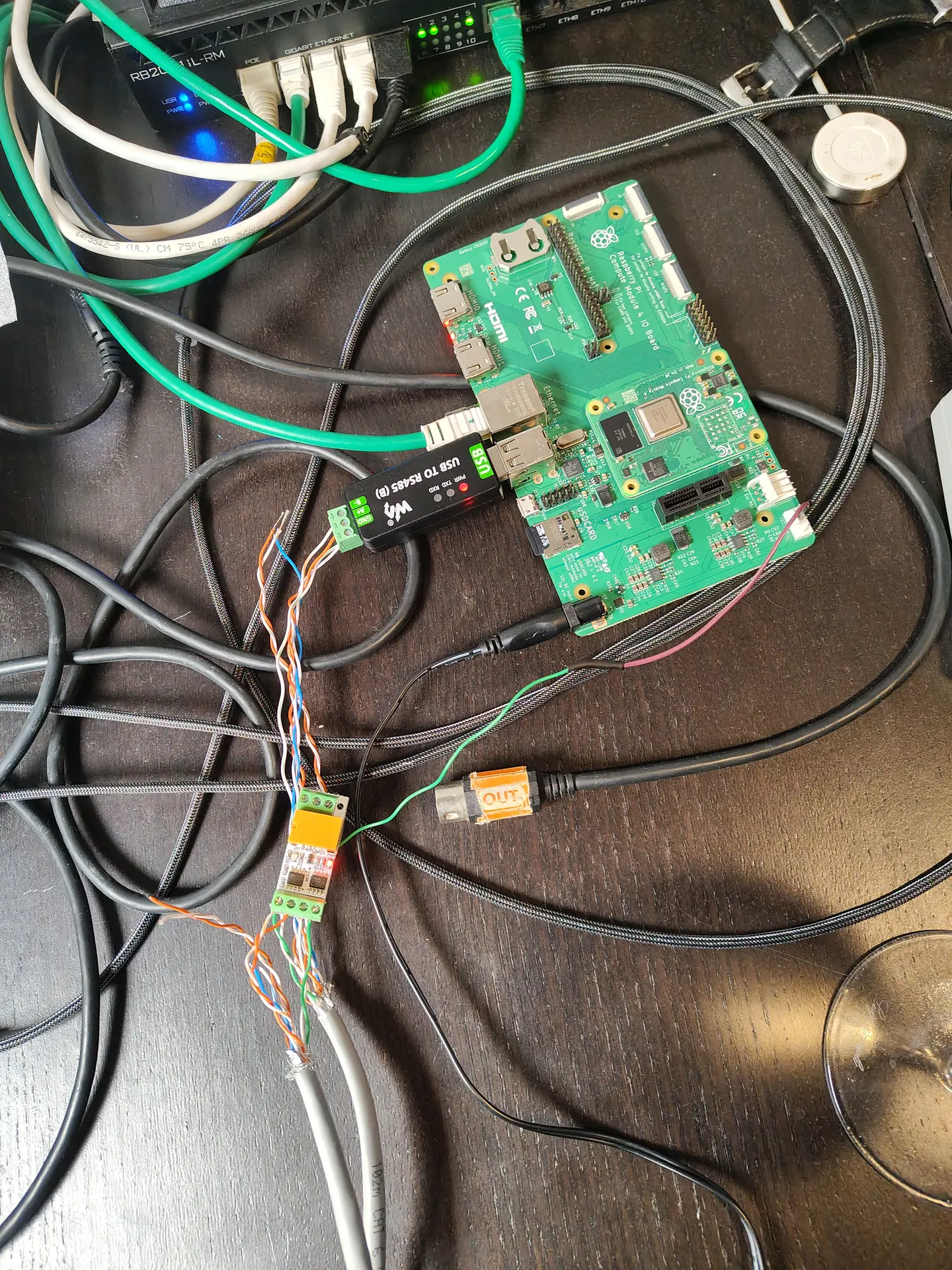
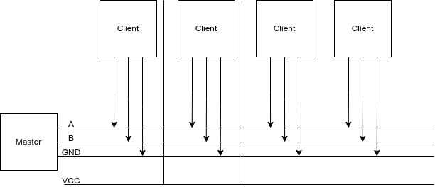
I’m going to put 4-wire ground cable in our garden, and a RS485/Modbus master controller in my shed. 4 Wires will have 12V low voltage, ground and RS485 A/B wires. This way I can control till 64 devices on a single cable.
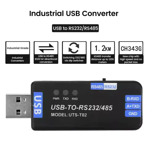
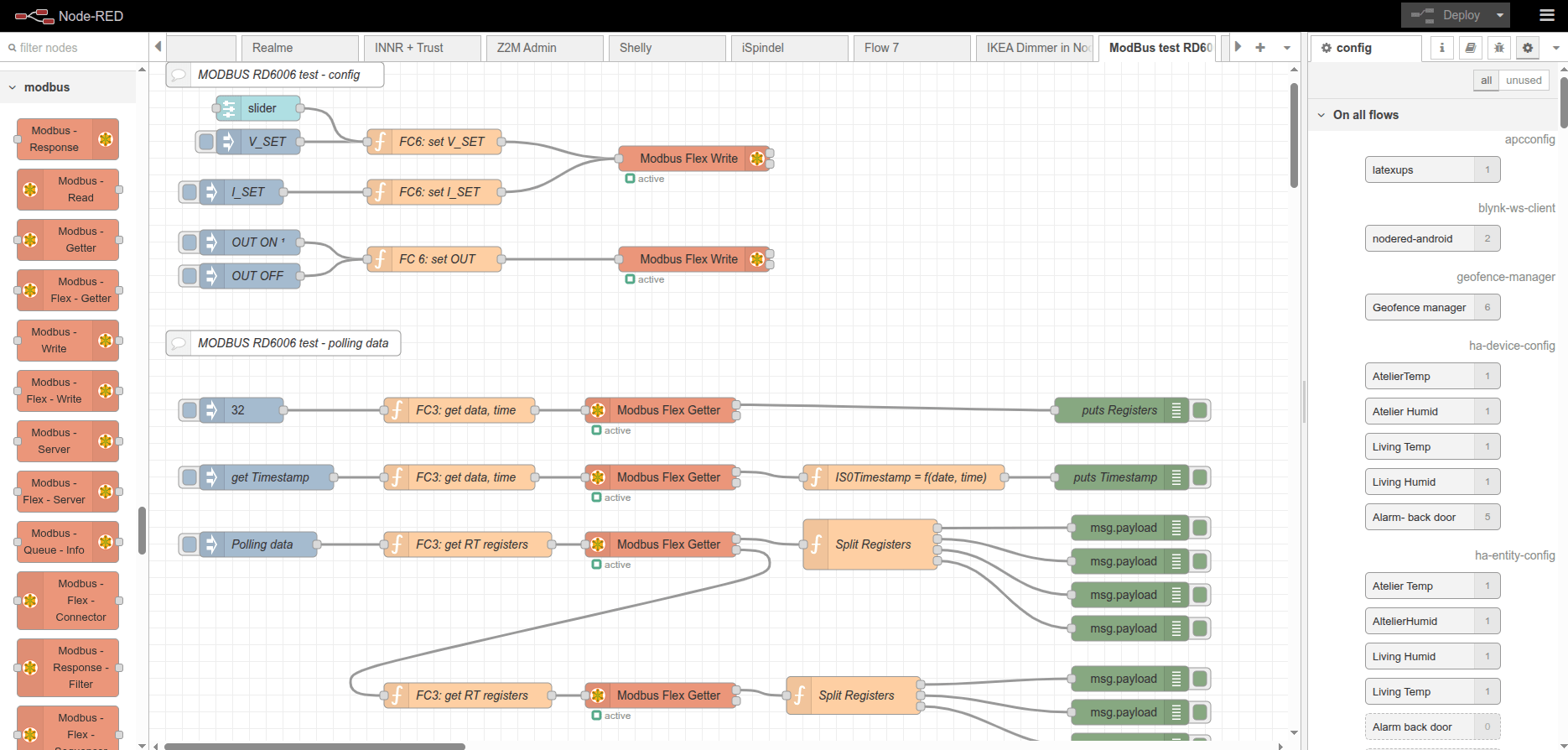
Below, a USB stick to connect the RS485 cables to a Raspberry Pi? Software is probably going to be a NodeRed instance connected to Home Assistant.
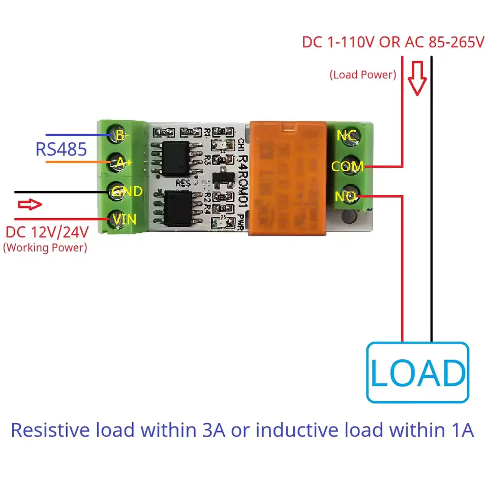
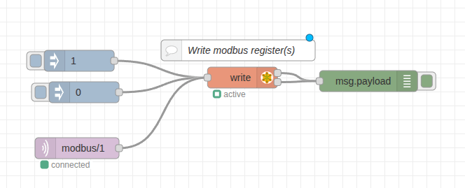
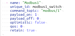
On/Off lights using a RS485 board and relay. These can be bought on a single PCB and can control 220V. I am probably going to use generic outside lamps and refit them for 12V led or 220v, with those RS485 controllers.
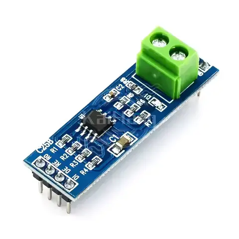
Test PCB
The above left part will be encased in resin or alike. Right PCB is for testing only.
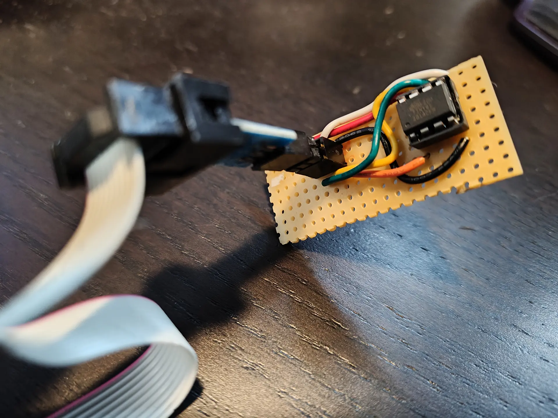
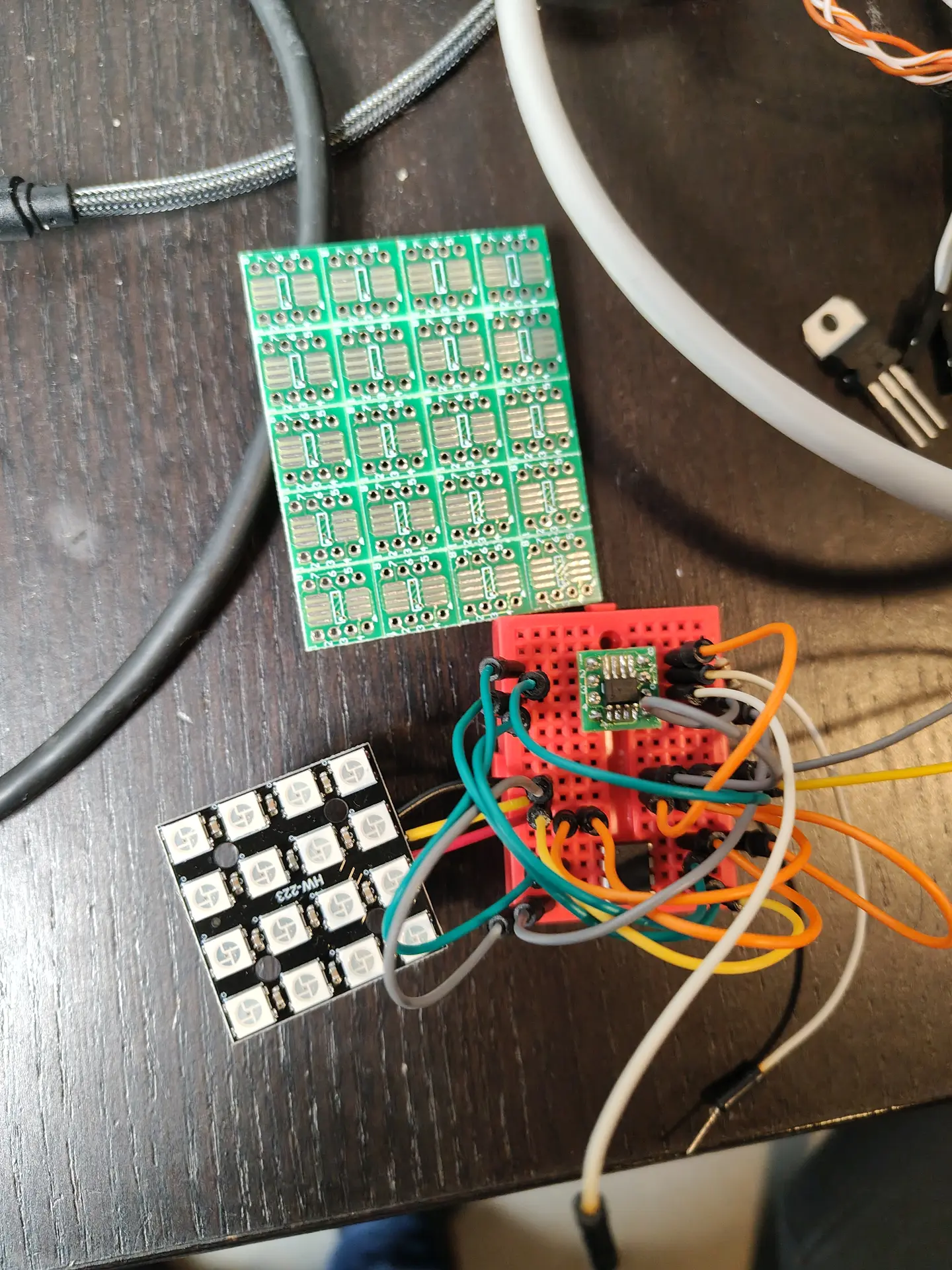
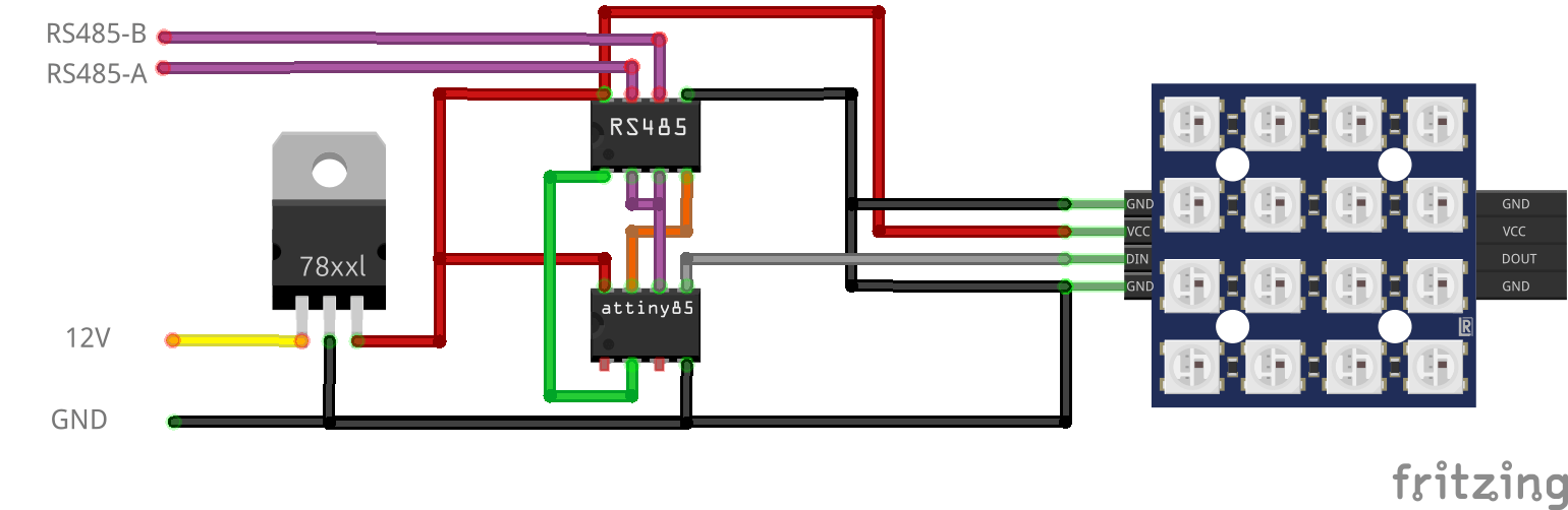
For dimming RGB lights, I made the below design.
NOTE: This needs 120ohm end resistor and capacitors over the 7805.
12V to 5V using a 7805, RS485 8pin DIL/DIP and a ATTiny85 8pin DIL/DIP. Plus a 4×4 RGB Matrix. These also encased in resin.
More information on the ATTiny85 and programmer can be found here:
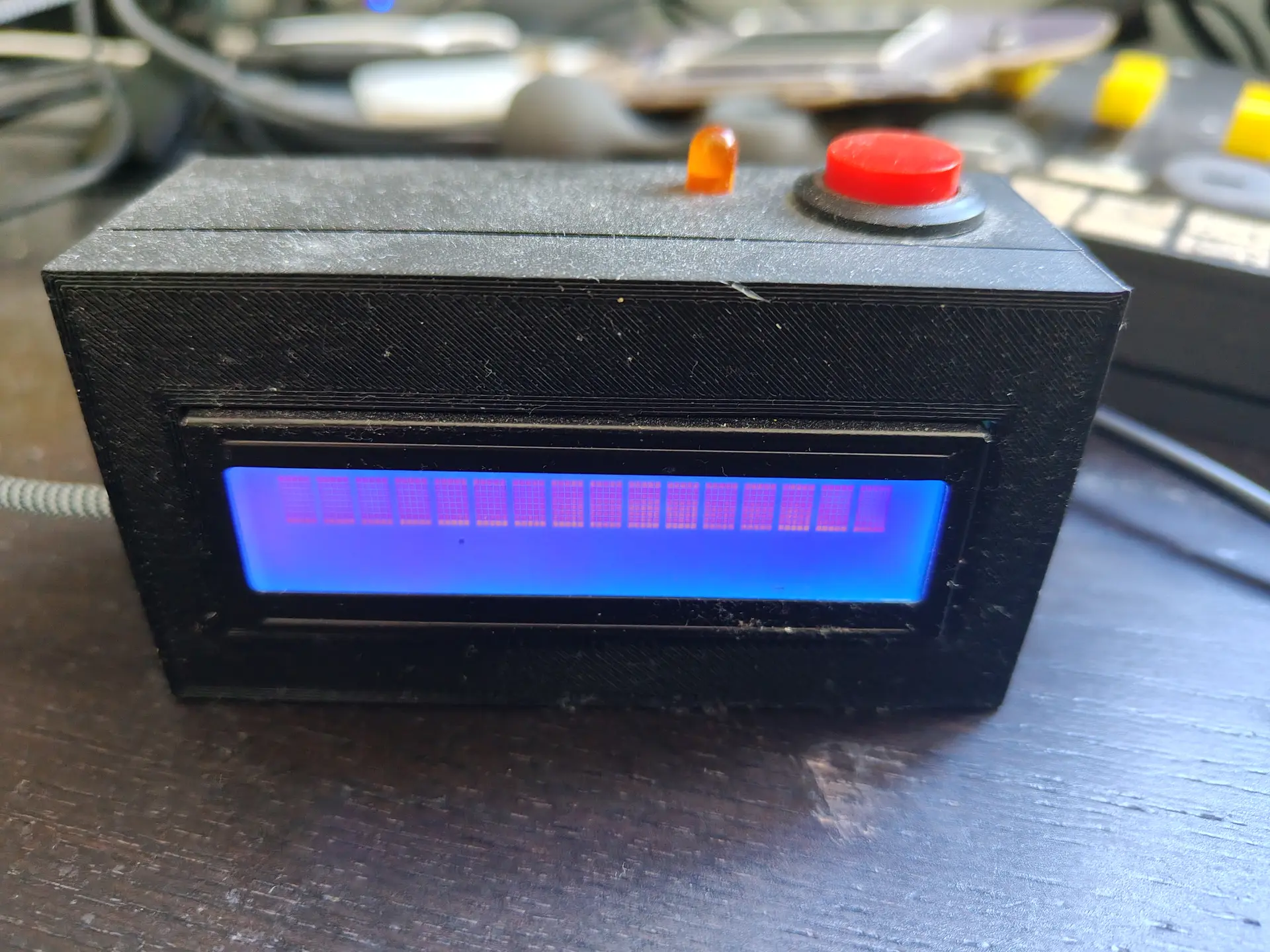
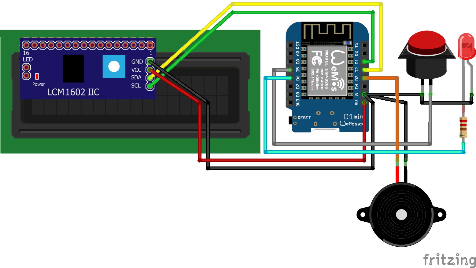
A while ago I made a little notify thingy using an LCD display, LED, button and a buzzer.
V1V2
Some friends of mine made one also, and today I was talking to a new guy. I could not find this project on my site .. again .. so I’ll post it now.
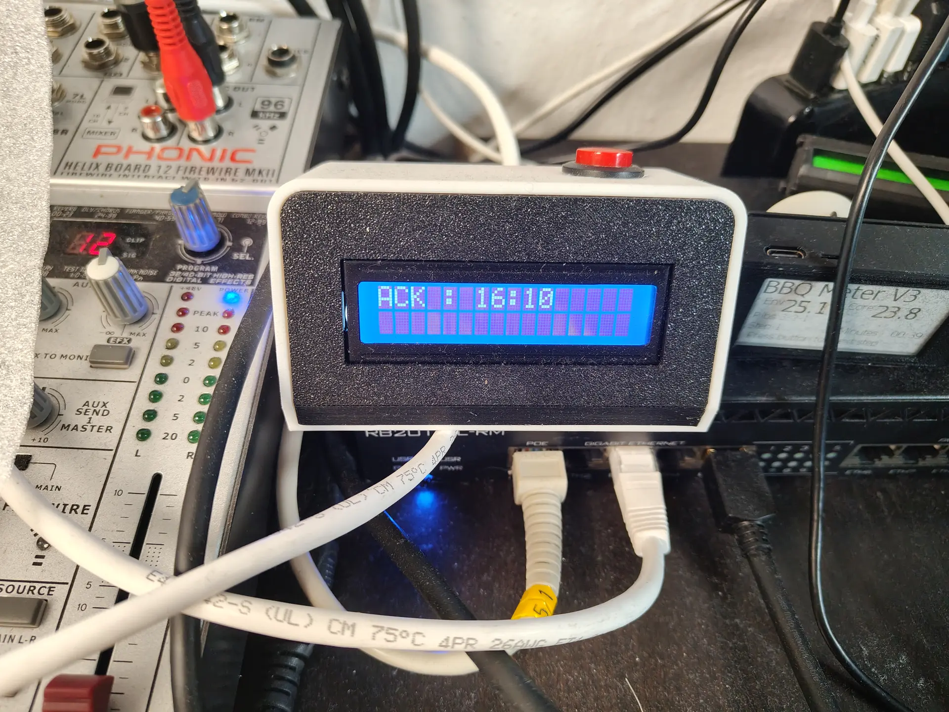
Some things it does right now
Front door opens
Door bell rings (because my lab is in the garden)
Girlfriend is 10Km away, so let’s start cooking
Garage door opens (friend of mine uses this to know when kids arrive)
More .. because it’s very easy to customize in Home Assistant
Doorbell pressed: Led starts blinking, backlight LCD enabled, text displayed on LCD, Buzzer sounds (or plays a RTTTL ringtone) LCD backlight on and buzzer beep until acknowledge button pressed.
Heating for brewing: temperature on display, led on when temperature reached. Press acknowledge to start timer.
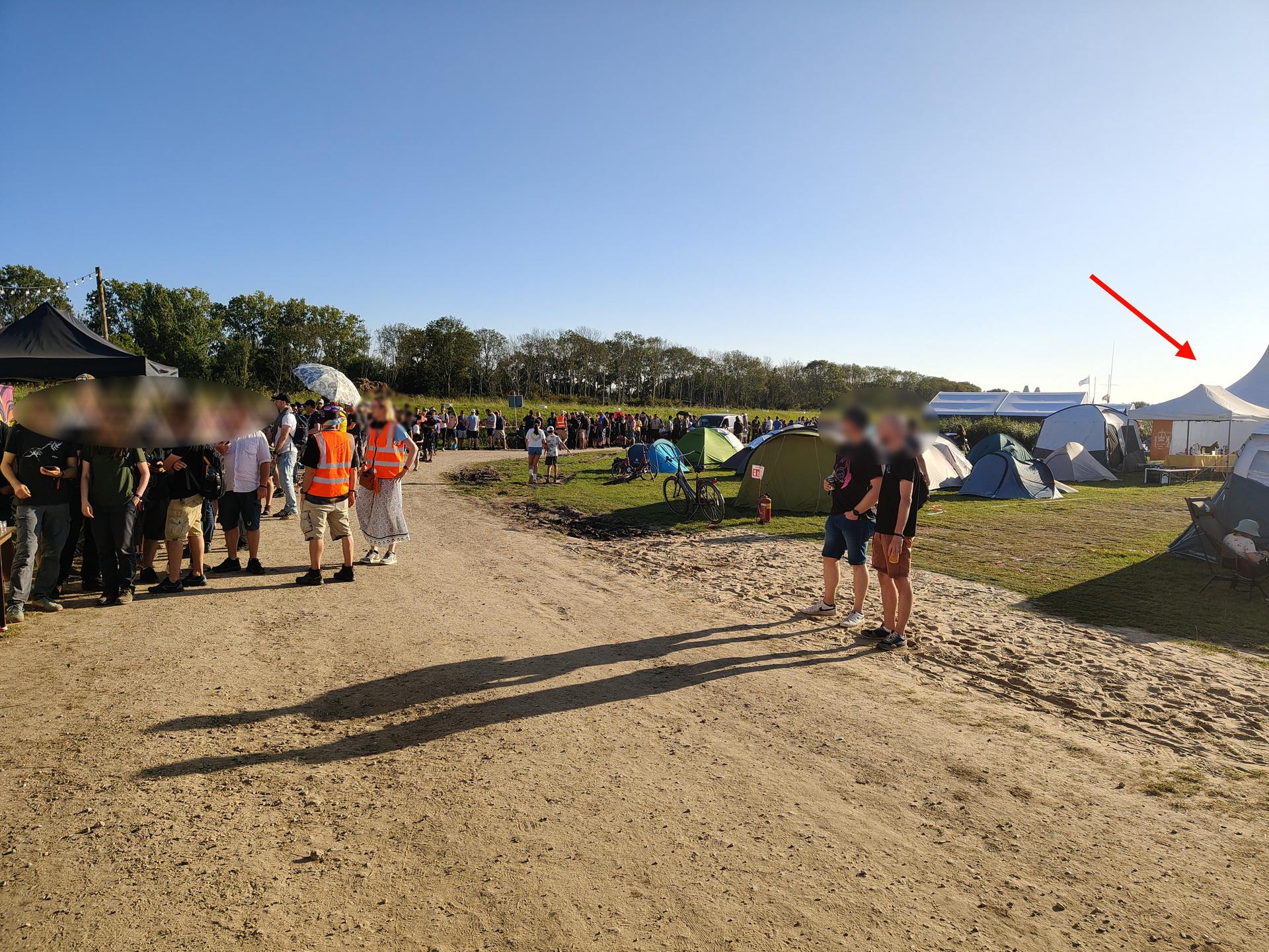
We went to WHY2025 a hackers camp in the Netherlands.
The first time I went was in 1997, with Bigred. Many followed after that. Tyrone, Bigred were also there from our old Crew. Coline joined me several times since 2005.
I joined the Badge team, and was making spacers for the Badges in bulk using my 3D printer. Also made some fancy cases.
CasesSpacers
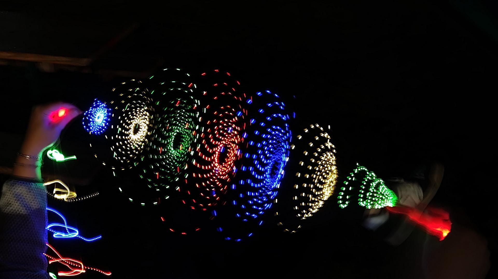
In case of doubt .. more leds!
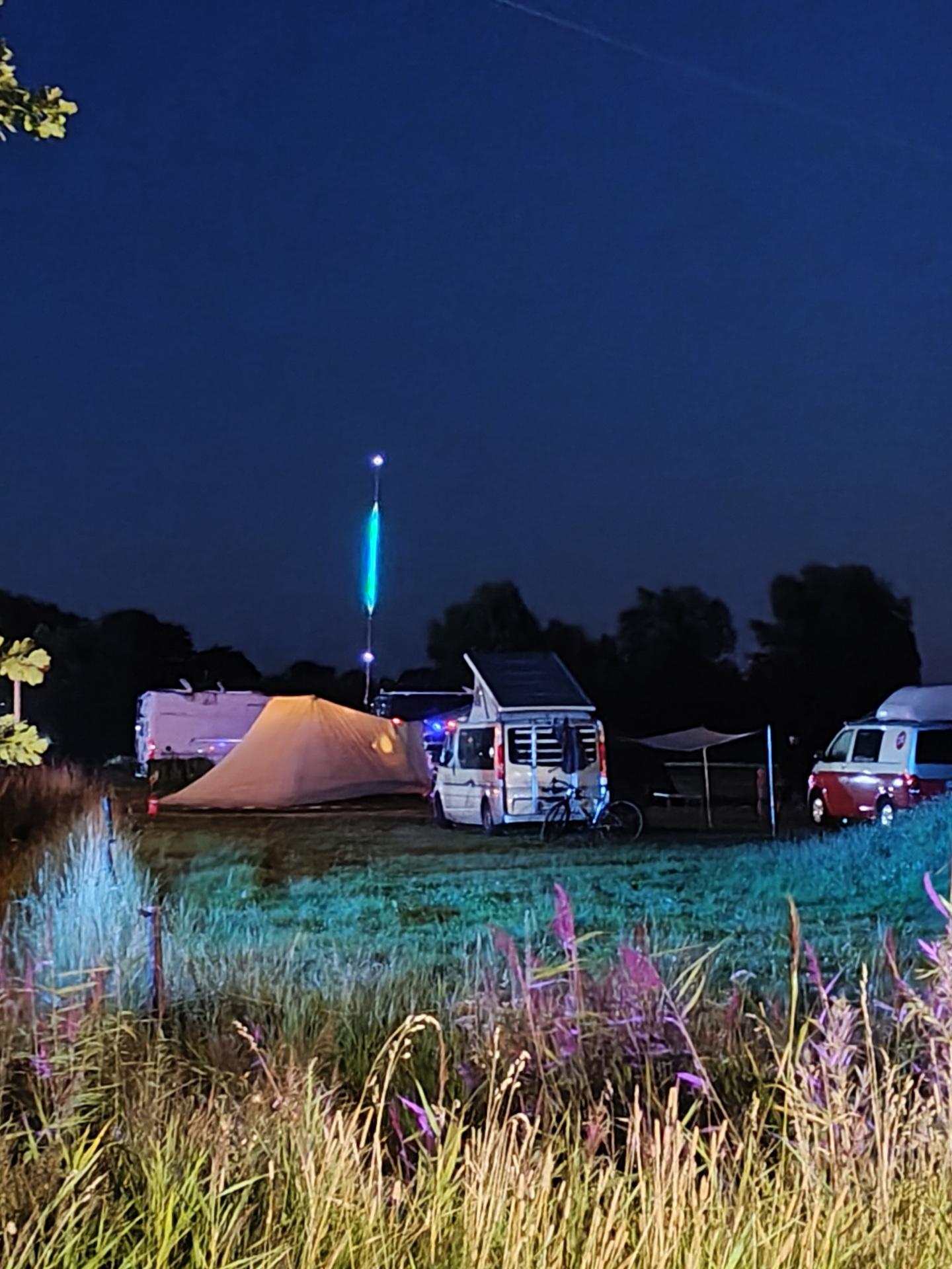
Our campsite with 7m Led stringMust have more leds!
Nice weather, good friends. New friends. Booze. Food and Hacking. We visited a lot of talks and enjoyed the music. (And fire)
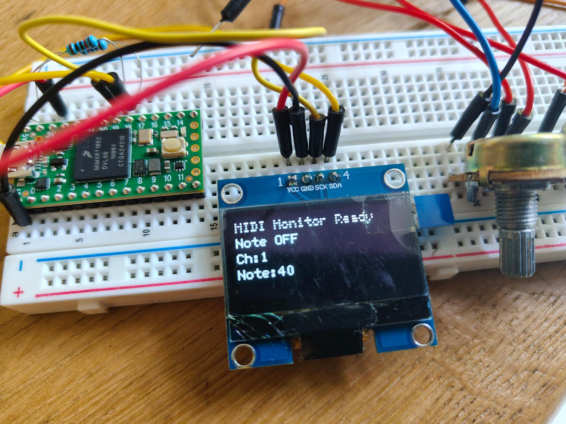
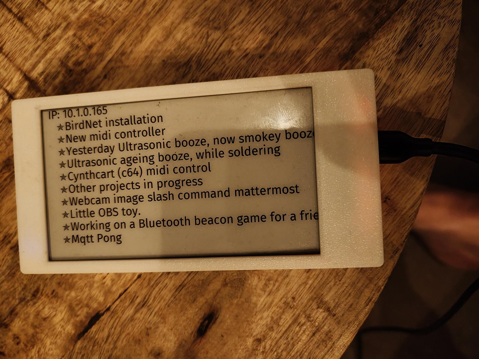
I worked on: RSS feed on a epaper display, Midi monitor and the MQTT Pong website.
RSS Feed display
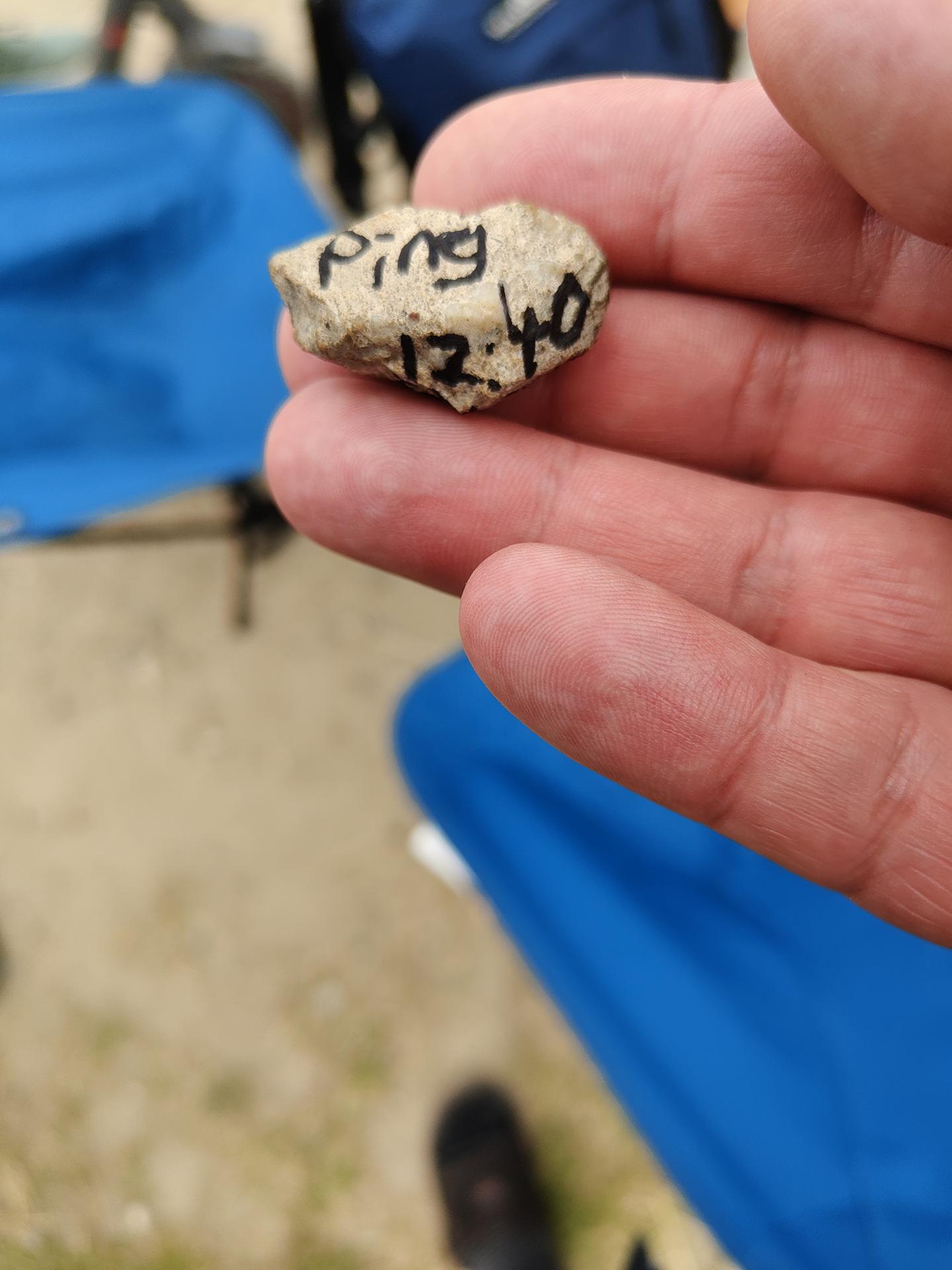
While waiting in line for the Badge:
A stone was passed from behind! It was a ping request. We passed it forward, and 15 minutes later a TTL time exceeded stone came from the front of the line. You gotta love those nerds!
Some other stones
The Badge: This should have got much potential .. Many misses, much to learn.
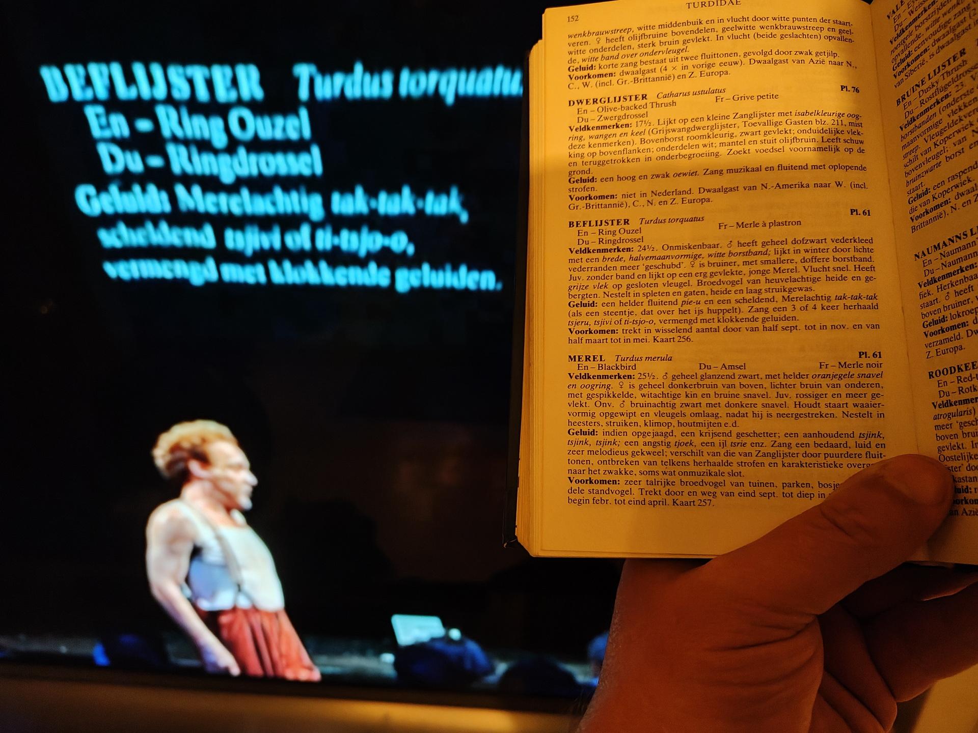
I bought Peterson’s Vogelgids, just for fun. It’s an old version, but that’s on purpose.
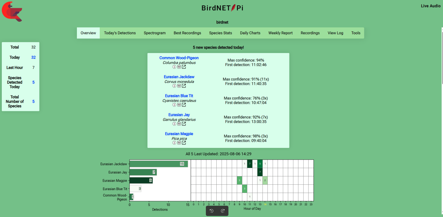
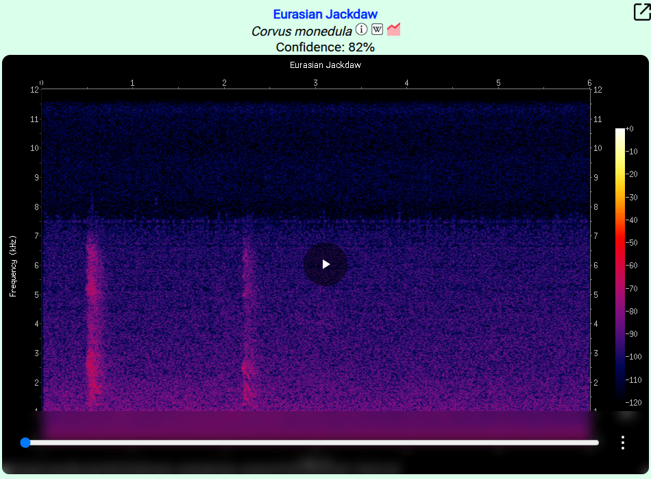
Then I saw a little project named BirdNet Pi. (I used the Android app already)
This is a Raspberry installation which recognises bird sounds. And gives you statistics about the detected birds. Cool for identifying birds in my garden.
Next to do : Integration in Home Assistant
Bert Visscher has the same book.
"If something is worth doing, it's worth overdoing."