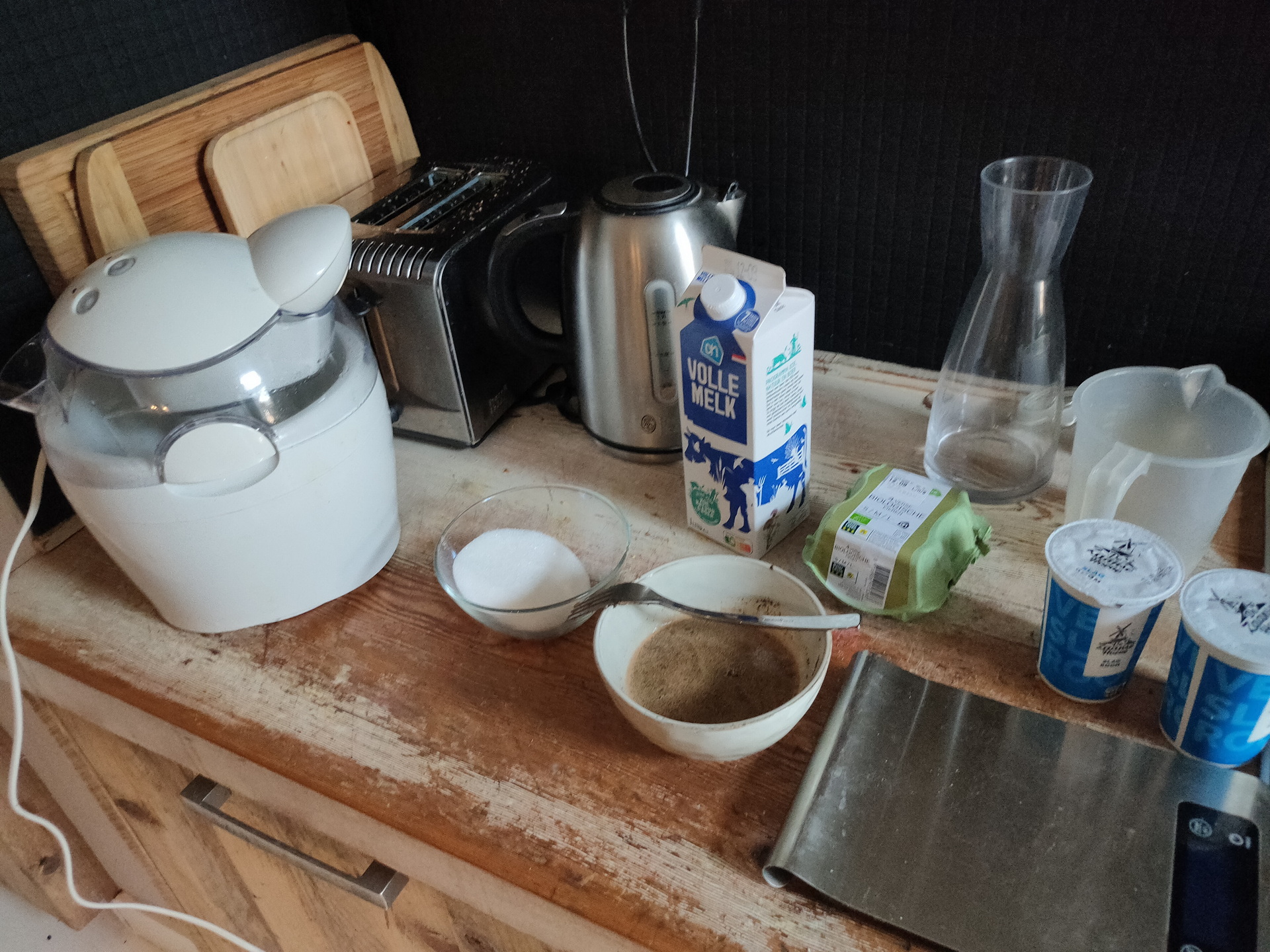
Still hot outside, and i like coffee. So what about some coffee icecream!
Ingredients:
200ml Milk (whole)
3 spoons coffee
90gr sugar
4 egg yolks
425ml liquid cream
Place a fine meshed strainer over a container. Put the coffee in the seive. Heat the milk (allmost boiling) and pour it over the coffee. Let it cool. Dissolve the sugar in 150ml water. Bring to the boil for a few minutes. Let this also cool for a few minutes. Pour the sugarliquid to the container holding the eggyolks. Add the liquid cream and the coffee-milk solution. Cool in the refrigerator and put into your icecream maker. Thats all.
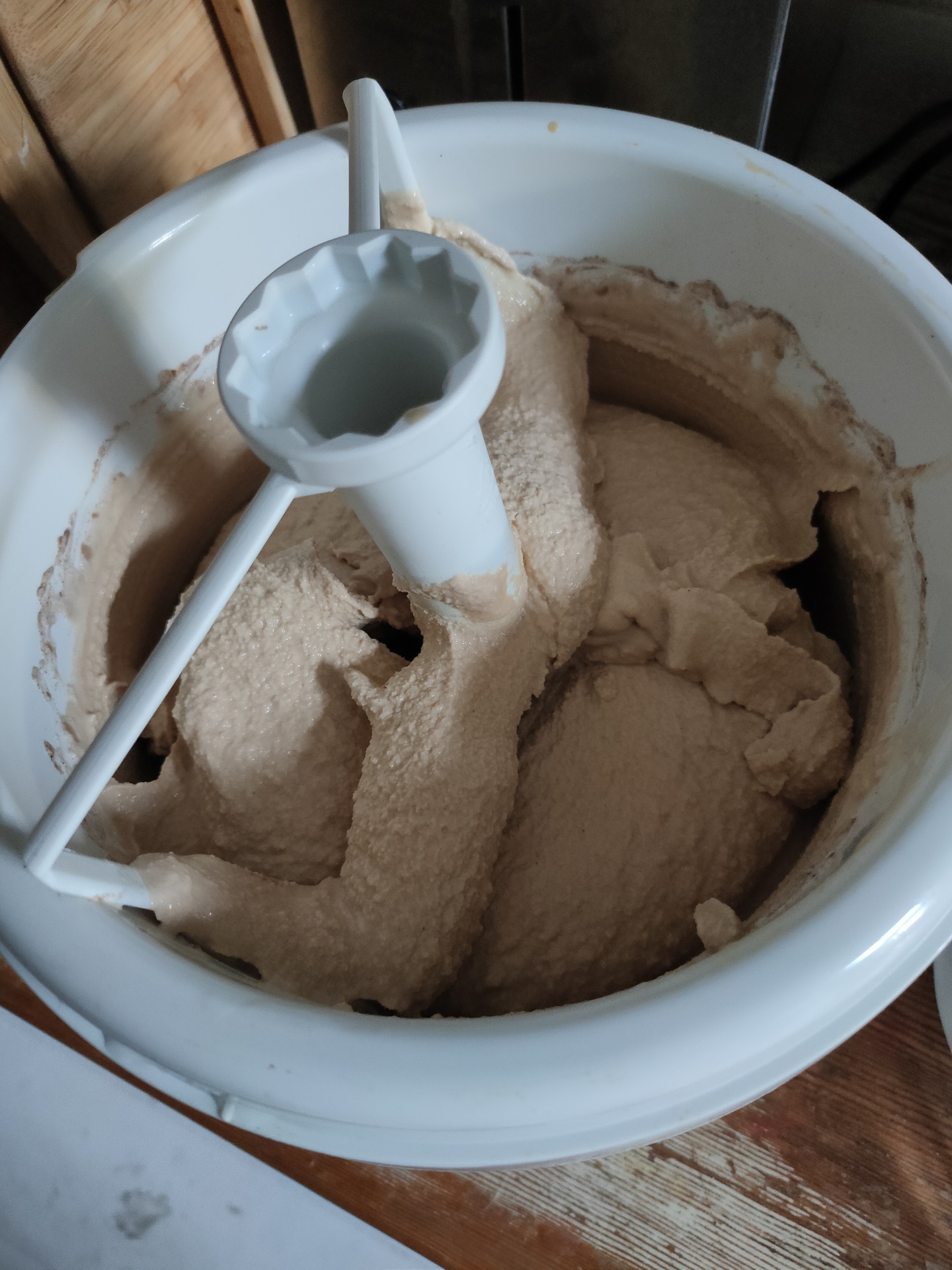
Icemaker is a Cucina – HR2305
Used this ice maker for many years, a lot of different icecreams we made!
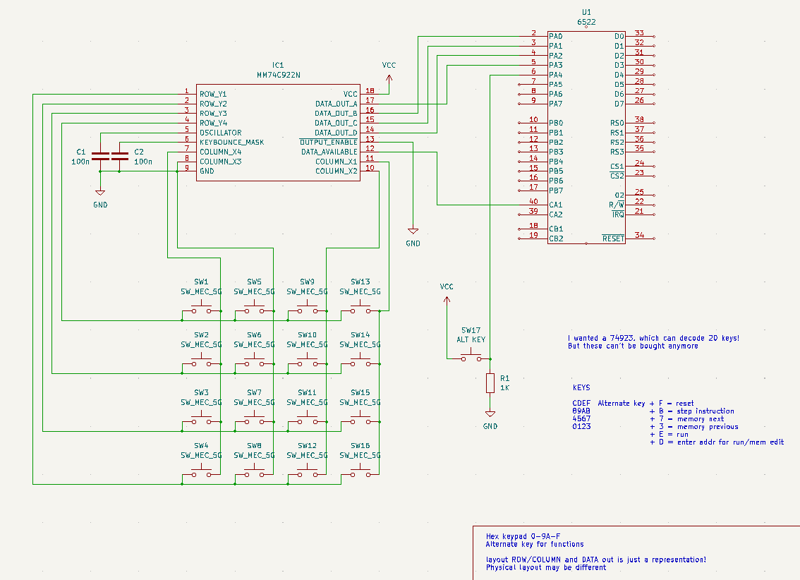
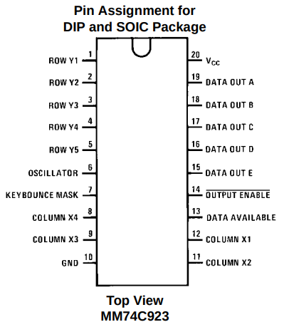
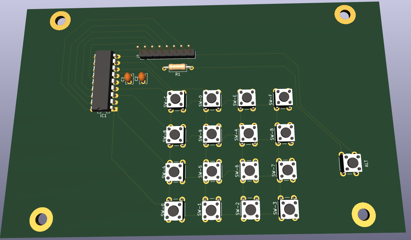
Above is my design for a hex keyboard to enter opcodes in hex using a simple monitor program. i used a 74ls922 which can decode a 4×4 matrix. I’d rather had a 74ls723 which can encode 20 keys.
Nowhere to be found. So i have to think of a new plan.
Now it is configured as follows:
C
D
E
F
8
9
A
B
4
5
6
7
0
1
2
3
When pressing the alternate key
addr (to implement)
run (1/2 implemented)
reset (to implement)
step instruction (to implement)
memory next
memory previous
PCB design for matrix hexboard with place for notes
Meanwhile i’ve ordered new keys (the ones i’ve been using for my photomanager project and wnat to have a setup like this:
?
?
addr
run
reset
C
D
E
F
?
8
9
A
B
step
4
5
6
7
mem next
0
1
2
3
mem prev
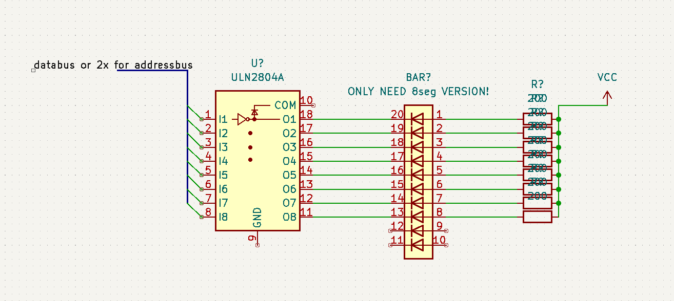
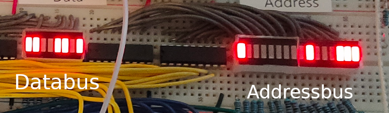
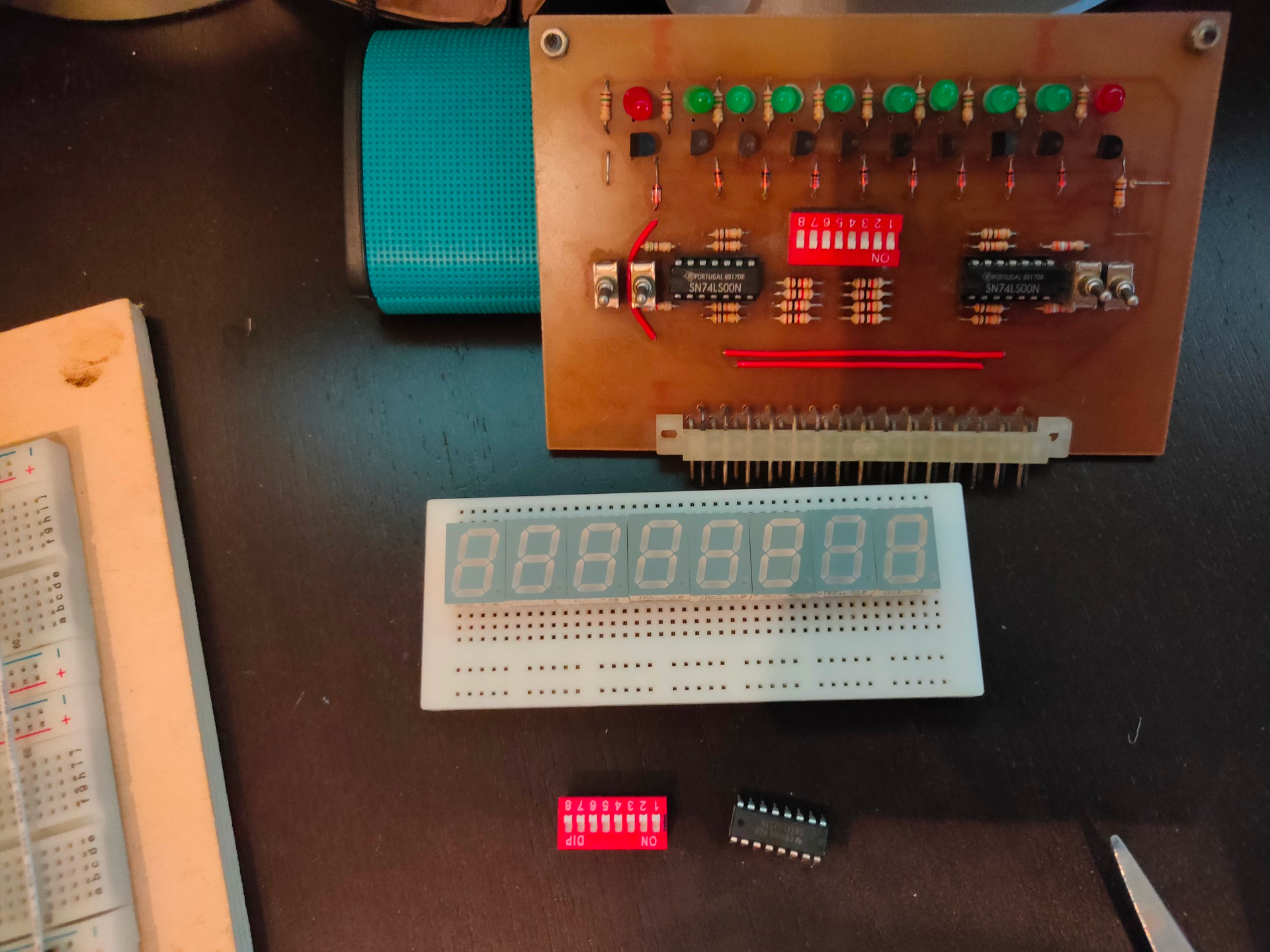
When you want to show the status of busses and alike, you can’t use a led and restistor directly on the bus, it will require too much current. So i’ve been using below schematic which uses a darlington array.
Now i can display databus, address bus and i’ve been using this for address decoding logic and hex keyboard.
I’ve implemented a second VIA chip, and ordered components to amplify the SID sound part
I play several instruments, and know a lot of tunes by heart. But for some instruments i’d like to have a music sheet in front of me. When playing new tunes or from my old stash, i need it on paper also. And when i do, I’d like my music nicely printed and in the same style.
So i’ve been using multiple programs and tools to get a result i can live with. I’ve got a huge collection of pipe and folk tunes, but whenever i decide that i’m going to play it more often then i’m going to re-create the music sheet. The musicsheet will be printed and put in a folder. But also as PDF wil be placed in my calibre server, with i use to provide my tablets and phones with a digital version. For automatically generating a PDF musicbook i’ve written some scripts. These PDF’s i can use with my DIY bluetooth page turner.
For my bagpipe tunes i started a long time ago with a dos version of Bagpipe Music Writer. Getting a decent result from your printer was a b*tch. But it was do-able.
Several other programs i’ve tried but few stuck. CelticPipes, Ceol Mor, Bagpipe (French), MusicTex, Lilypond for example. I don’t like to click a symbol and place it on the bars, i like typing .. so i’m a little biased. For midi and printing multi bar/staff music i also used Cakewalk Pro.
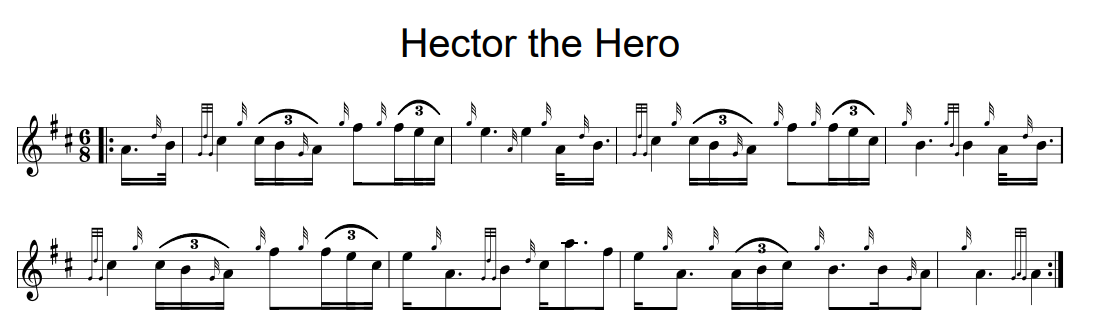
I use this mainly for Whistle and skeletal melody lines for Uilleann pipes (no ornaments)
Bagpipe IS possible but hard and ugly.
Multiple voices (harmony) is possible.
Chord names can be places above bars, as well as vocals.
I’ve made scripts with headers and footers to get the same output result.
Creating the music is typing the notes and ornaments in a text file.
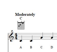
Little chords for guitar mandoline are also possible.
# Edit/createing a abc music file
vi musicpiece.abc ; edit with plain editor
abcm2ps musicpiece.abc ; convert to ps
ps2pdf14 Out.ps musicpiece.pdf ; ps convert to pdf
Also EasyABC i use occasionally
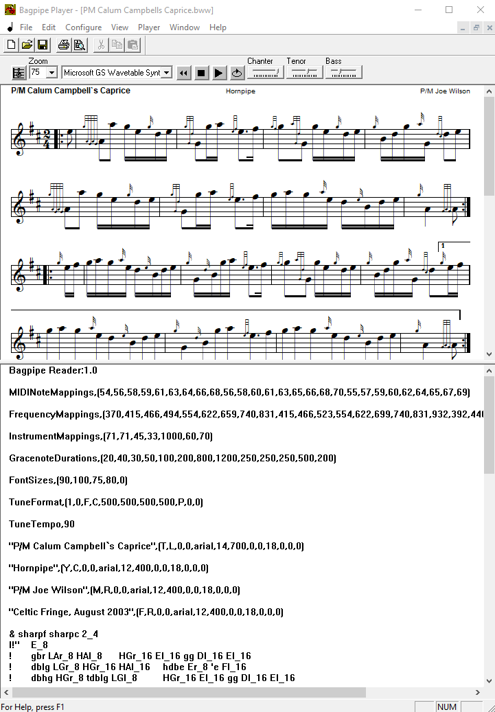
Bagpipe music:
I still use Bagpipe Music Writer, but the free Player, which is a full version also. (Long story) Using wine on linux it is usable.
In the past i made a virtual machine which could be controlled by a web form and some CGI scripts. I could paste a “bmw” score in a webform which would be send to the virtual machine, a BMW program would be started, printed the tune as a PDF that was send to the website again.
For a long time i also had a abc music to PDF convertor on my website.
I like the way of writing the tunes .. just type abbreviations of ornaments to print. When you know these you are faster than using a mouse!
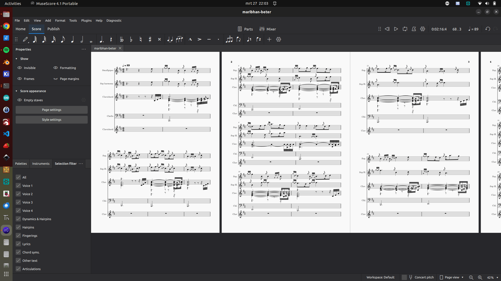
There is no way to write harmonies. In the past i’ve been using a pdf editor to merge music bars and align those by hand. I’ve stopped doing that. I just print 2 versions. Sometimes i use MuseScore for harmonies and multiinstrumental sheets
Mhairi Bhan Og with multiple other midi instruments (a test composition I did in 2024)
I’ve used a lot of programming languages, and besides that a few scripting languages.
Scripting is used to automate stuff, but probably use other tools under the hood. A programming language can probably do this by itself. Most of the time a programming language needs compiling into a executable form. Whereas a script is directly intepreted at runtime.
I’m not good at programming, but i understand the syntax and can read most of it. My programming is mostly by example/copy-paste. Below a list of programming languages and a table below that some scripting languages.
Sooo .. what do i like, still use and why?
Bash is my swiss army knife. Making Web stuff? – PHP Iot – C and Javascript Advanced programming/Longer programs or Machine Learning – Python
And because of recent projects … i have to mention 6502 machinecode!
Programming languages i’ve used
Basic
The first programming language i learned. There are many dialects for many different systems.
Pascal
I learned to program in school. Generic pascal and later Turbo Pascal
PLM/86
This is relatively unknown programming language. Written for intel processors. It used a lot of ms-dos subroutines. Like dsso which stands for dos-standard-string-out. dsso(@(‘Print this text’,eos)); And called a dos routine like below (assembly example) mov dx,(messageaddress) mov ah,09h int 21h
Assembly
Started with 6502 assemby on my little home computer (a vic-20). After that i learned to program 8085 assembly in school. Also learned a little Z80 programming. When i got a amiga i started with 68000 assembly. And getting the hang of it, some friends and me started programming 80×86.
C
For a project I needed C programming to control a parallel port, for example for my controllable webcam. Also recently the microcontrollers like the Arduino’s are programmed in C/C++
Perl
Perl was also a interesting language, i bought myself a book and started with the examples. One of my friends was a Perl wizard, but i could never get the hang of it. Even with his help.
Tcl/TK
TCL stands for Tool Command Language, i used the TK extension. So Tcl/TK i used for creating GUI tools in linux. But like what i later used zenity and yad, i think these are more scripting languages.
PHP
PHP i used extensively, one of my first big projects was a tunesearch engine with a mysql database.
Python
The last years i’ve been using python more and more. Python has become the de facto standard for IT.
Haskell
Well .. it is a programming language but i only use it to configure my Xmonad desktop.
Javascript
I’ve made a lot of webbased nonsence. PHP/CGI scripts/flash but i also used javascript. Now i’m primarily using javascript for NodeRed
Scripting languages i’ve used
bat
Dos batch files is a kind of scripting language
Ksh
Korn Shell, i did a workshop ksh because i was a AIX admin. Didn’t use this much, because you could install the linux toolkit, and could use bash after that.
Bash
I write a lot of things in bash, this is my preferred tool for fast and easy automation. When it’s web based i use PHP
Lua
I had to write some plugins for my Flightsim Setup
What about Sql, Dbase, Sed, Puredata and blocky those are all on the Programming Lanuages page of Wikipedia??? Well those i find more of a application markup language. Then you can say abc-music and bmw (bagpipe music writer) are languages also!??
Some call Ansible a programming language, but this is incorrect. It is driven by python scripts and yaml config files.
Below some code part examples of different CPU assembly code
#6502
    PUSH CX
    PUSH DI
    PUSH SI
    MOV AX,cry
    MOV BX,(2*40)
    MUL BX
    MOV DI,AX
    ADD DI,(2*31)
    MOV SI,adr1
    SUB SI,8
    MOV CX,8

Z80
    LD H,00H
    LD B,01H
    LD A,(IX+00)
    OUT (01H),A
    LD A,(IY+00)
    OUT (02H),A
    DJNZ LUS3
    LD B,01H
    LD A,(IX+07)
    OUT (01H),A
    LD A,(IY+07)
    OUT (02H),A

#8085
    LDA 2050
    MOV H, A
    LDA 2051
    ADD H
    MOV L, A
    MVI A 00
    ADC A
    MOV H, A
    SHLD 3050
    HLT

#68000
    bsr send
    bsr delay2
    move.w #$38,d0
    bsr send
    bsr delay2
    move.w #$38,d0
    bsr send
    bsr delay2
    move.w #$01,d0
    bsr send
    bsr delay2
    move.w #$0c,d0
    bsr send
    move.w #$06,d0
    bsr send
    rts

#80x68
    mov bx,split
    and bx,1111111111b
    mov dx,3d4h
    mov al,18h
    mov ah,bl
    out dx,ax
    mov bl,bh
    xor bh,bh
    shl bx,1
    mov bx,[bx+offset ormsk]
    mov al,9
    out dx,al
    inc dx
    in al,dx
    and al,10111111b
For assembly i use or used below: vasm – vasm is a portable and retargetable assembler – which can be used for a lot of different CPUs masm – a assembler for 80×86, i used this for programming on DOS machines. Also for little projects i used the alway available debug executable. seka/masterseka – programming 68000 on my amiga
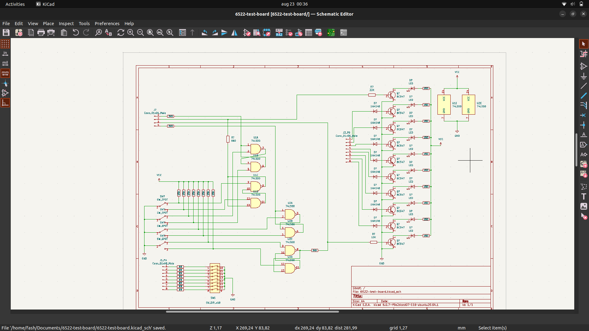
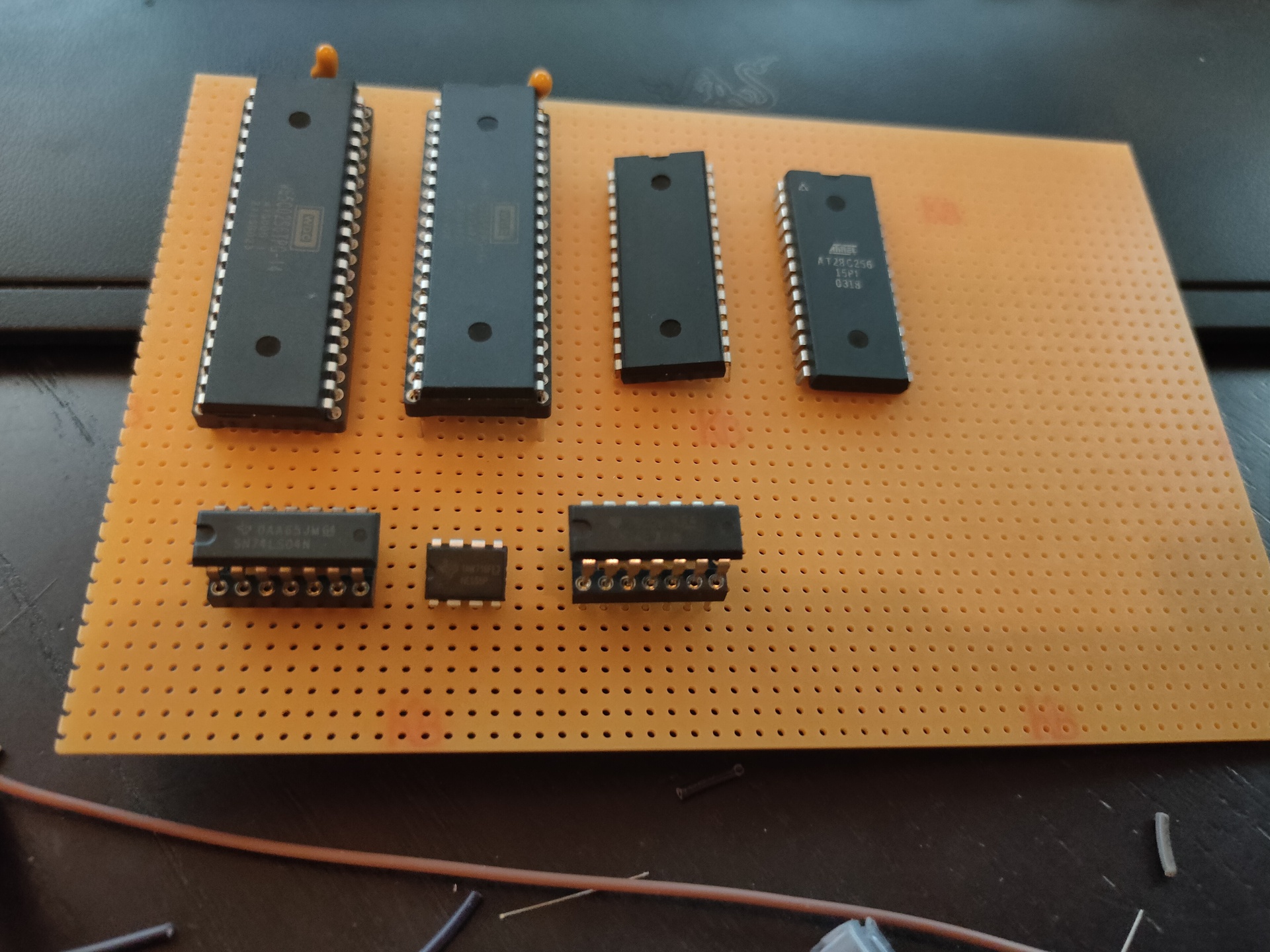
Above is my Kicad design (reverse engineering print below, which was made for my 6802CPU, which i could use to test the 6822 PIA) The 6822 is simular to 6502 in design. So i’m going to redo this for my 6502. The 7 segment displays are a start of hex-keyboard/display combo i’m going to post more of in the next days.
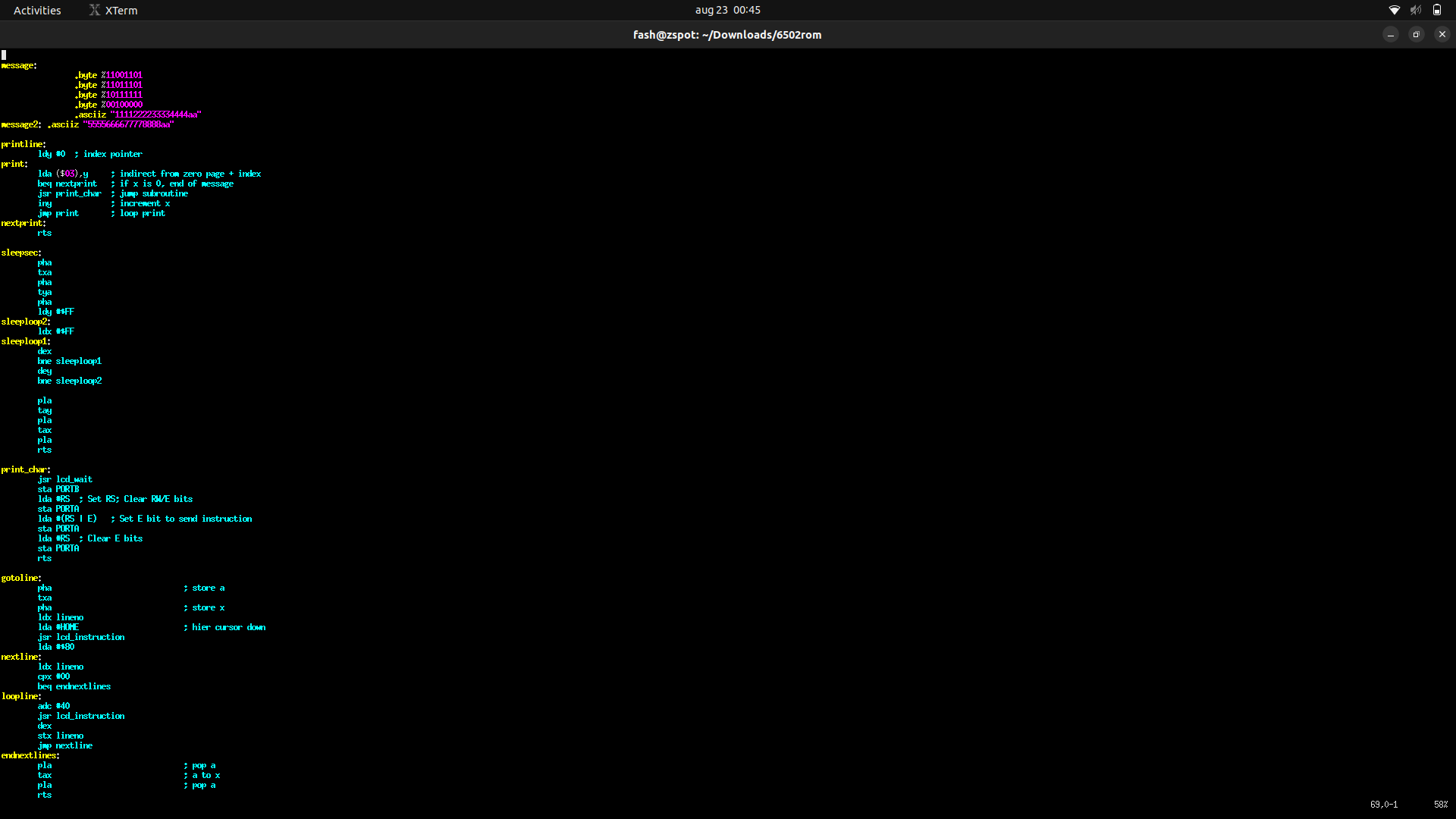
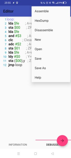
Below a part of the rom for the LCD dual line display.
Part of the ROM assembly code, top part is text (o.a. japanese)
Started to write routines which i can call to manipulate the display. Setting the pointer to a message, setting the line to use and a subset of controlls like: Center, Right, binary to ascii, scrolling, etcetera
        lda #0             ; set line number
        sta lineno         ; store
        jsr gotoline       ; goto line in display
        lda #<message      ; get address from message and store for printline subroutine
        sta messagestore
        lda #>message
        sta messagestore+1
        jsr printline      ; print

        lda #1  ; set line number
        sta lineno      ; store
        jsr gotoline
        lda #<message2
        sta messagestore
        lda #>message2
        sta messagestore+1
        jsr printline
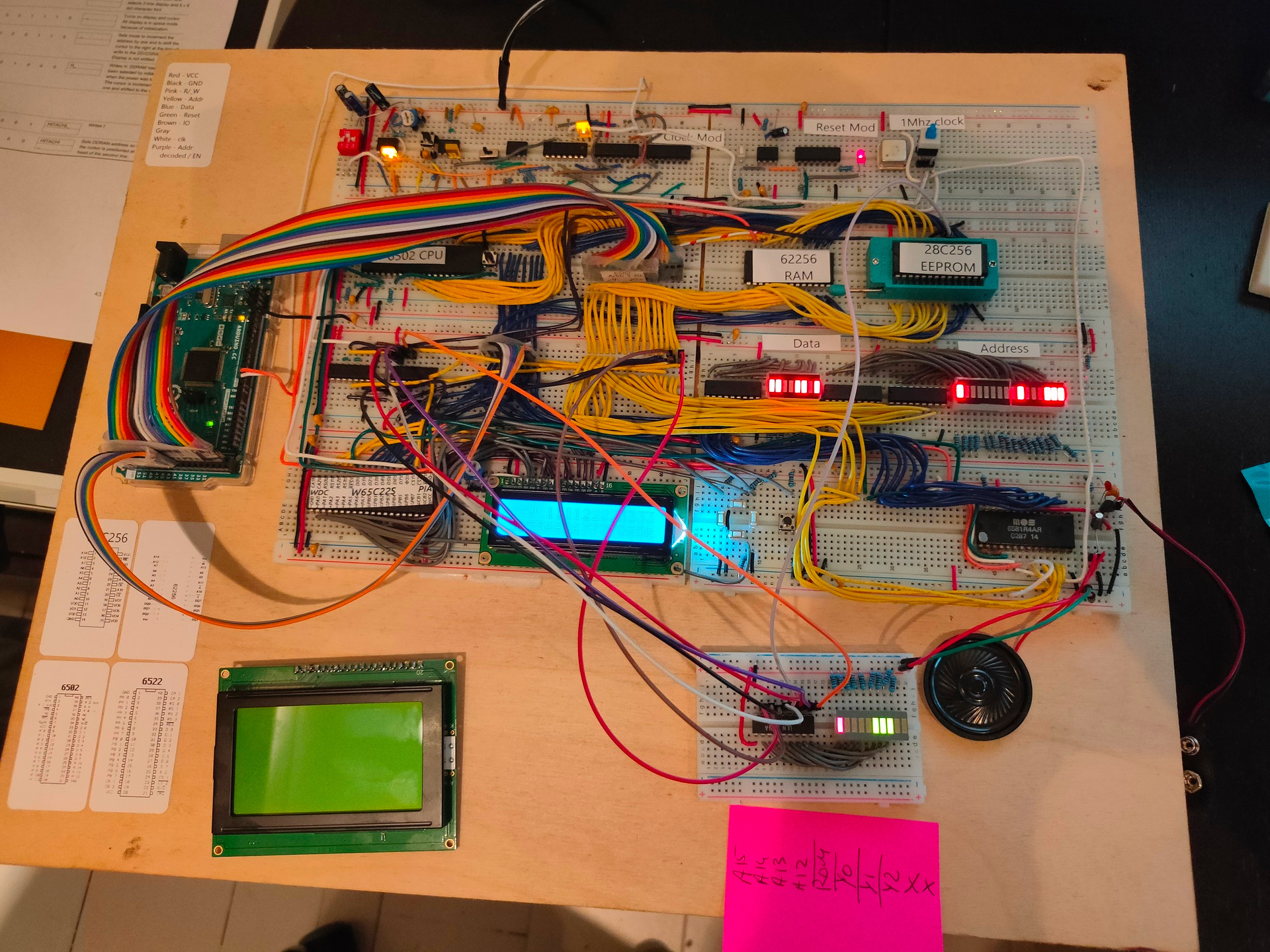
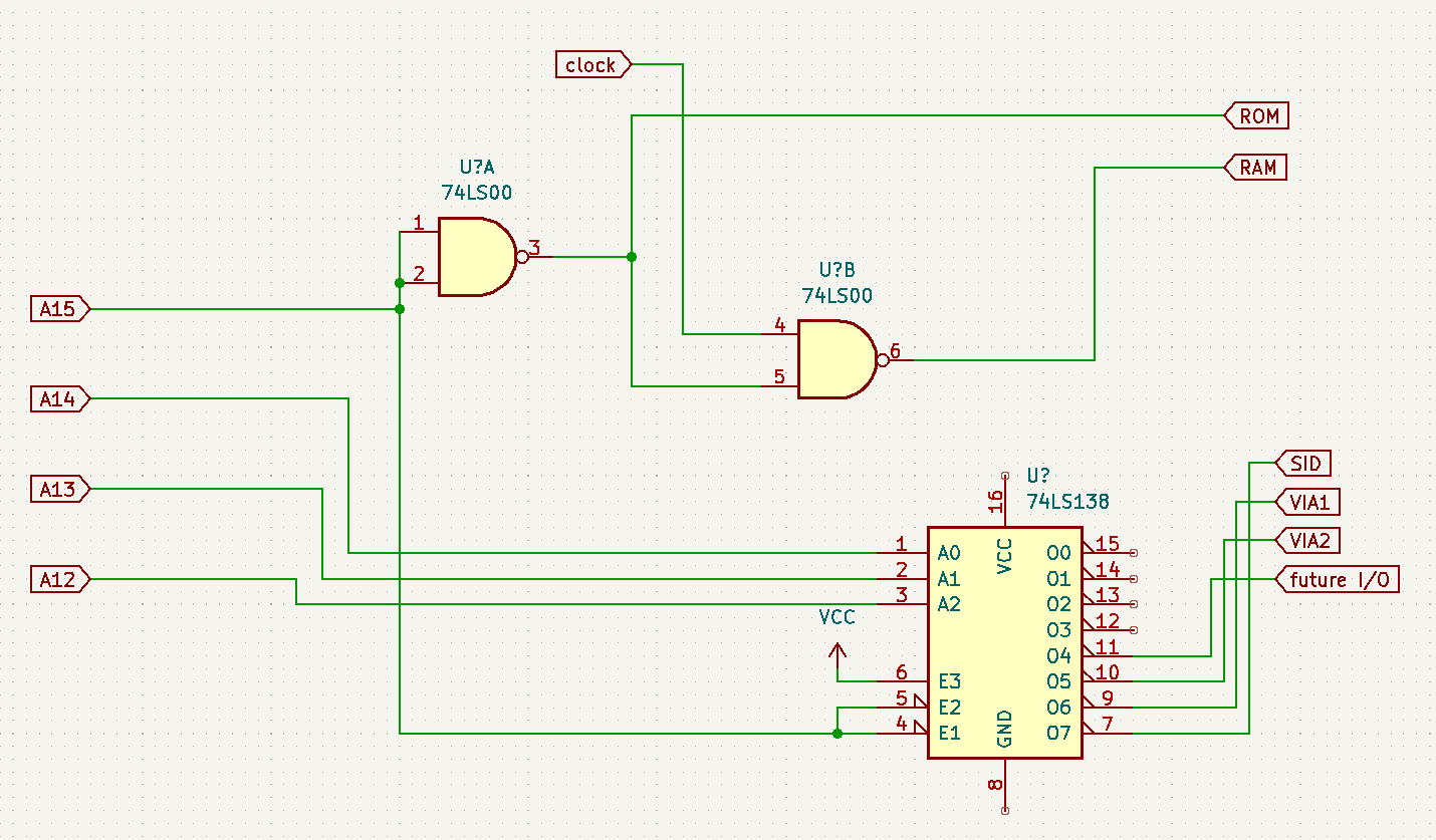
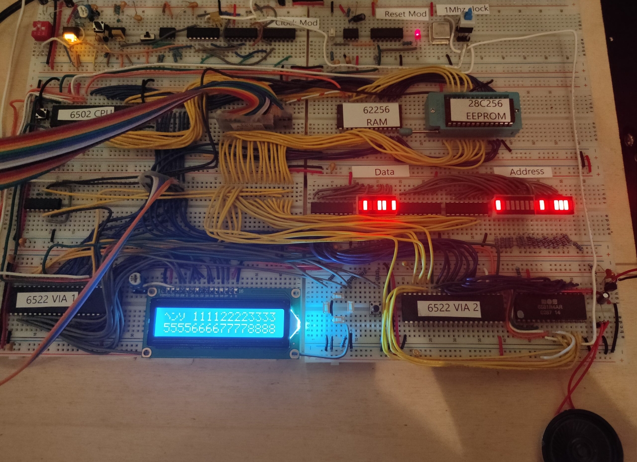
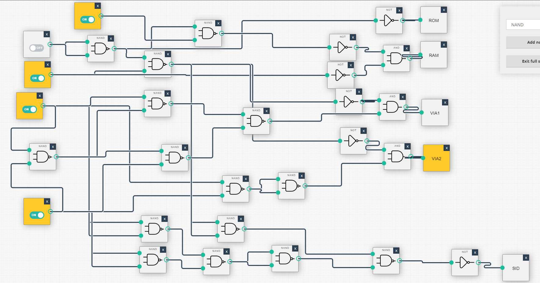
Above additions: New address decoder Below left the new graphical display, below right a test board which shows address lines and decoded chip-enable lines.
A15 high -> ROM A15 && A14 low -> RAM combination of A15 low and A14 high – A13 and A12 wil select peripherals.
Adress decoding
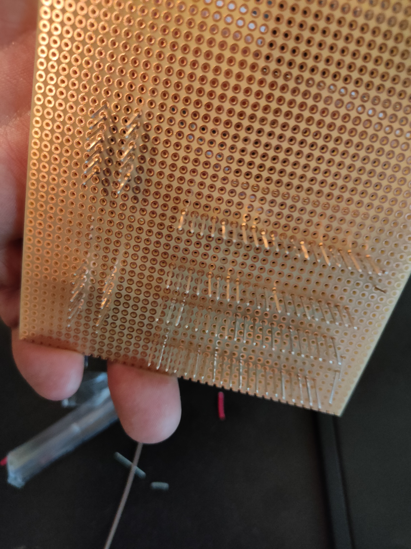
Start of a wirewrapped version
Above is a start of a wirewrapped version, i also started a PCB design in KIcad that will continuously be changed as i alter designs.
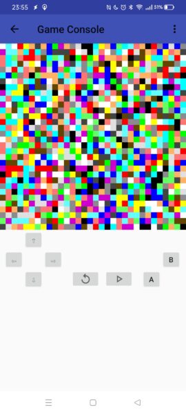
UPDATE SID Working! Using new address decoder.
SID = $7000

makesound:
	lda #0
	sta SID+$5 ; Channel1 - attack/decay

	lda #250
	sta SID+$6 ; Channel1 - Sustain/Release

	lda #$95
	sta SID+$0 ; Channel1 - Frequency low-byte

	lda #$44
	sta SID+$1 ; Channel1 - Frequency high-byte

	lda #%00100001
	sta SID+$4 ; SAW + Gate

	lda #$0f
	sta SID+$18 ; Volume max
There was a place i’ve worked, they did something weird with network masks. The cause was probably because of changes in the network, and some things had to be re-routed. When doing routing you use a network mask, this mask is used in tcp/ip routing. When an IP is not in a local network, which boundaries are set by the mask, the protocol will use the gateway to break out of the network.
Example time!
192.168.1.2 – computer IP 192.168.1.0 – network it sees as local 255.255.255.0 – network mask 192.168.1.1 – gateway of example
in binary
11000000.10101000.00000001.00000010 – computer IP 11000000.10101000.00000001.00000000 – network 11111111.11111111.11111111.00000000 – mask (should be al 1’s until the boundary of the network)
The 1’s in the mask should work as a filter!
What i’ve seen was something like a mask 11111111.1111111.00111111.00000000 ! This gave the network a gap into another network!
This is NOT encouraged, don’t do this. Theoretical and seen in a real live environment .. it CAN work
Another weird one
I was asked to look into a problem at the Johan Cruyff Foundation. Btw I ran into the guy, but I didn’t know who he was, they had to explain. (I ‘m not into football)
Some PC’s sometimes could not connect to the network. Sometimes the printer didn’t work. A colleague of mine looked into it and could not find it.
The order in which powered up the PC’s and printer seems to matter.
From the 7-8 devices only 6 worked.
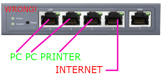
So I drove to Amsterdam, turned on a pc, and looked at its network settings. It was getting a IP, but it was a PUBLIC one! Looking at another machine, it was also a public one!
The router was locked inside a cabinet, but I knew the famous dutch telecom provider had done something like this! (below)
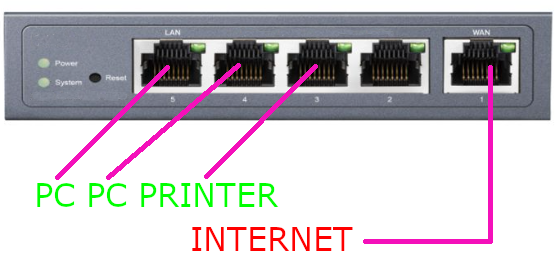
As it should be (4 ports example)
The organisation had a range of 6 public addresses, thats why not all machines could connect. These windows pc where connected directly to the internet! (Some virusscanning required I think!)
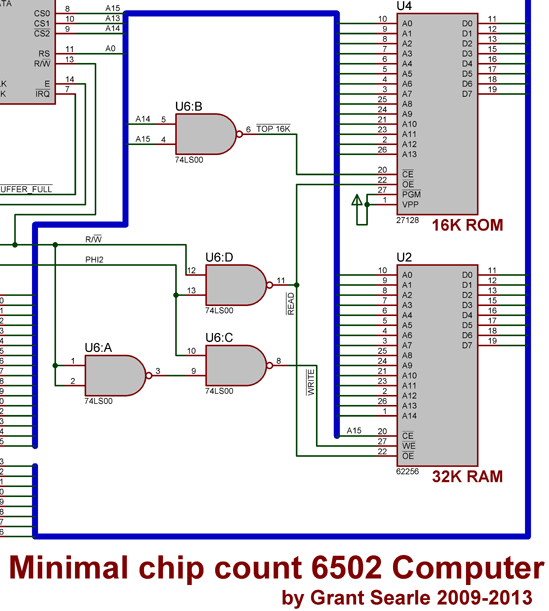
For accessing the different components in computers you have to use the Address Bus. In most 8 bits computers there are 16 address lines.
The CPU on a 6502 can access 65536 addresses (16 bit ). But most chips in the circuit have just a few address lines. So the chip to use has to be selected using a CE (chip Enable) signal.
Old article i found on my fileserver from 1984
74 Series logic
Above example uses A15 combined with A14 to address the 16K ROM When using a 32k rom in the upper part of the memory, a15 can be used as CE
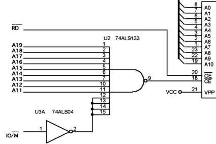
The 74ALS133 is a widely used decoder due to it’s many inputs.
Sometimes not all address lines are used for decoding, then you will get a repetition of the device in the memory map.
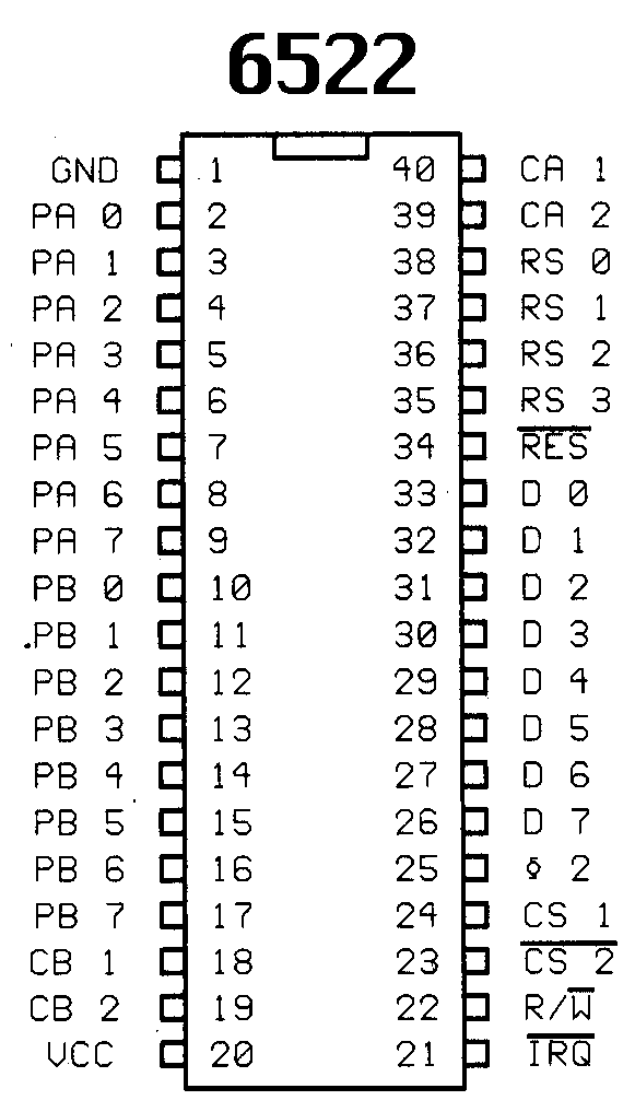
Above 6522 VIA has only 4 address lines RS0-RS3. But 2 chipselect pins (CS). If you connect the chip as below.
The chip would be selected when A15 is 1 and A14 is 0, A13-A04 it would not listen to. So its 4 bits addresses (total 16), would be repeated in a block $8000-$BFFF (10xx xxxx xxxx aaaa) 16384 addresses for 16 addresses on the 6522
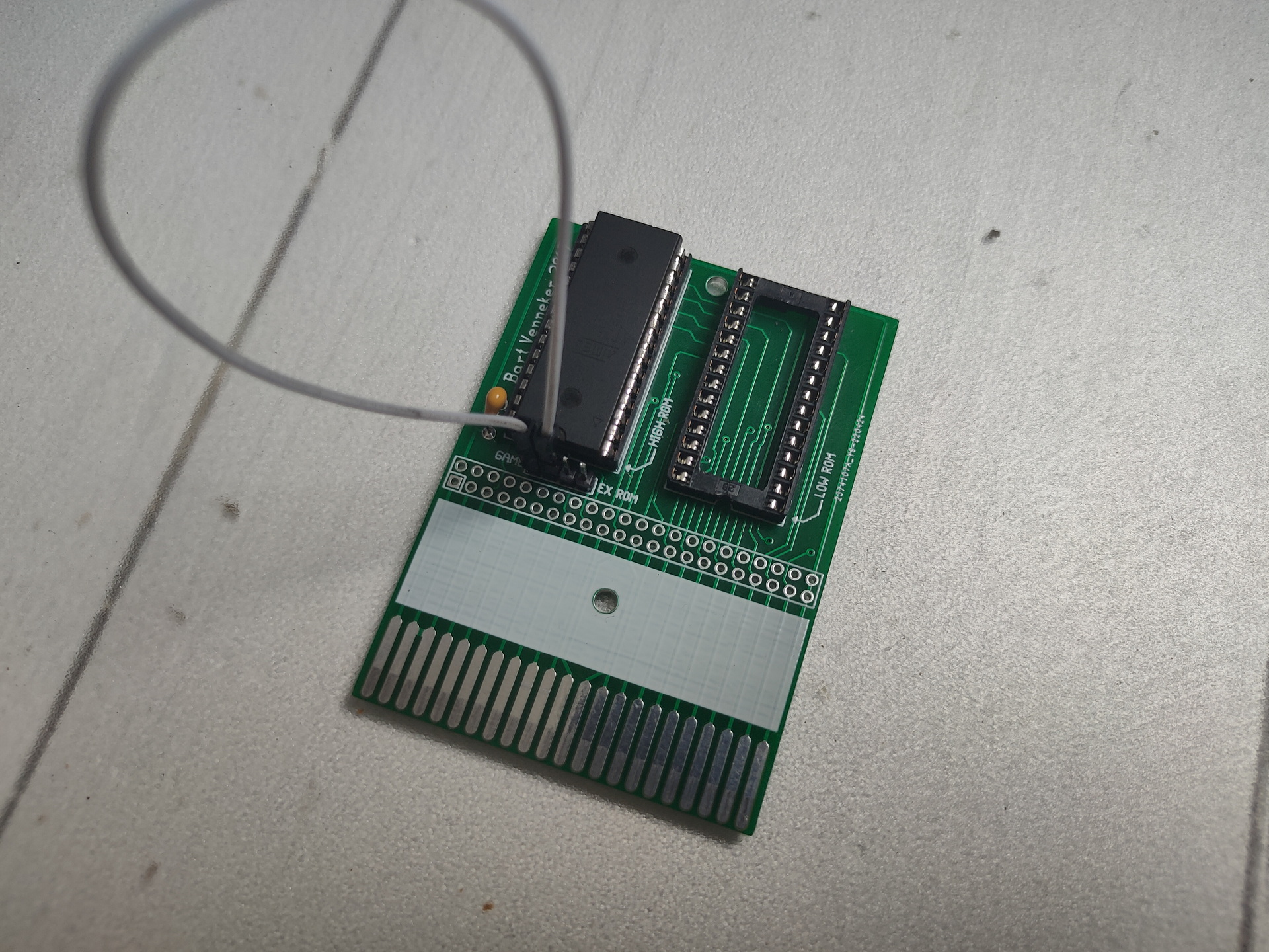
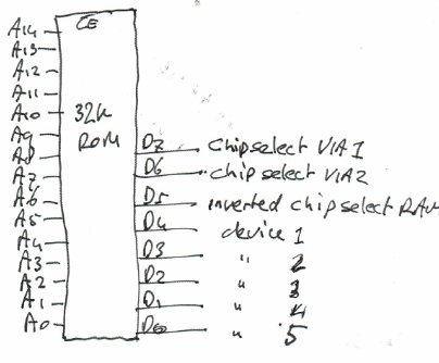
ROM
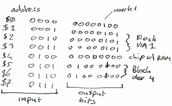
Another simple solution to get a more precise address decoder without using a lot of components is using a ROM. But this wil only work for low speeds! A eeprom is relative cheap
Example ROM as chip enable/select
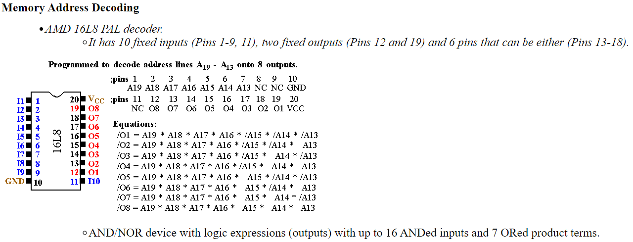
PAL PLA GAL
With these devices you can “program” a schematic which works as above example’s of the 74 series. But now you can do it using only one component.
PALs and PLAs are fuse-programmed, some are erasable like (e)eprom. Below a example of the code. Most of the PAL/PLA/GAL are hard to get and obsolete
;PALASM Design Description
;---------------------------------- Declaration Segment ------------
TITLE    pRAM PC_interface Address Decoder
PATTERN  pRAM97A.pds
REVISION H
AUTHOR   Trevor Clarkson
COMPANY  EEE KCL
DATE     30/05/97

CHIP  decode  PALCE20V8

;---------------------------------- PIN Declarations ---------------
PIN  1          AEN                                   COMBINATORIAL ; INPUT
PIN  2          A9                                    COMBINATORIAL ; INPUT
PIN  3          A8                                    COMBINATORIAL ; INPUT
PIN  4          A7                                    COMBINATORIAL ; INPUT
PIN  5          A6                                    COMBINATORIAL ; INPUT
PIN  6          A5                                    COMBINATORIAL ; INPUT
PIN  7          A4                                    COMBINATORIAL ; INPUT
PIN  8          A3                                    COMBINATORIAL ; INPUT
PIN  9          A2                                    COMBINATORIAL ; INPUT
PIN  10         A1                                    COMBINATORIAL ; INPUT
PIN  11         IOW                                   COMBINATORIAL ; INPUT
PIN  12         GND
PIN  13         IOR                                   COMBINATORIAL ; INPUT
PIN  14         ACK_HALT                              COMBINATORIAL ; INPUT
PIN  15         PLS_EN                                COMBINATORIAL ; OUTPUT
PIN  16         BRDW                                  COMBINATORIAL ; OUTPUT
PIN  17         MOD_CTRL                              COMBINATORIAL ; OUTPUT
PIN  18         RAM_ACCESS                            COMBINATORIAL ; OUTPUT
PIN  19         IO_16                                 COMBINATORIAL ; OUTPUT
PIN  20         LATCH_MOD                             COMBINATORIAL ; OUTPUT
PIN  21         LATCH_ADD                             COMBINATORIAL ; OUTPUT
PIN  22         P300                                  COMBINATORIAL ; OUTPUT
PIN  23         P300IN                                COMBINATORIAL ; INPUT
PIN  24         VCC

;PC address decoding functions (not all in this PAL)
;uses latched address to provide low-order address lines to pRAM/RAM
;       A3      A2      A1      R/W     Addr    Function
;       0       0       0       R       300     MFF_0
;                               W               not used
;       0       0       1       R       302     MFF_1
;                               W               not used
;       0       1       0       R       304     MFF_2
;                               W               not used
;       0       1       1       R       306     MFF_3
;                               W               Latch Module Number
;       1       0       0       R       308     PLS_Status  (pRAM status)
;                               W               PLS_Control (pRAM control)
;       1       0       1       R       30A     Weight/Connection-
;                               W                Pointer RAM access
;       1       1       0       R       30C     not used
;                               W               Latched RAM address
;       1       1       1       R       30E     not used
;                               W               pRAM_256 module control
;
; NB. IO_16 must be tri-stated when not in use

;----------------------------------- Boolean Equation Segment ------
EQUATIONS

/P300 = A9*A8*/A7*/A6*/A5*/A4*/IOR + A9*A8*/A7*/A6*/A5*/A4*/IOW

/BRDW = /P300IN * /IOW

/PLS_EN = /P300IN*/A3*/IOR + /P300IN*A3*/A2*/A1

; MOD_CTRL is active HIGH
MOD_CTRL = ACK_HALT * /BRDW * A3 * A2 * A1 * /IOW

; RAM_ACCESS is active HIGH
RAM_ACCESS = ACK_HALT * /P300IN * A3 * /A2 * A1

IO_16 = GND
IO_16.TRST = /P300IN
; enable 16-bit transfers

; LATCH_MOD is active HIGH
LATCH_MOD = /BRDW * /A3 * A2 * A1

; LATCH_ADD is active HIGH
LATCH_ADD = /BRDW * A3 * A2 * /A1

;----------------------------------- Simulation Segment ------------
SIMULATION
TRACE_ON A9 A8 A7 A6 A5 A4 IOR /IOW /BRDW /PLS_EN MOD_CTRL RAM_ACCESS IO_16 LATCH_MOD LATCH_ADD ACK_HALT /P300 /P300IN
SETF /A9 /A8 /A7 /A6 /A5 /A4 /A3 /A2 /A1 IOR IOW /ACK_HALT /P300IN
SETF /IOW ; test P300 doesn't respond
SETF IOW /IOR ; test P300 doesn't respond
SETF IOR
SETF A9 A8 /A7 /A6 /A5 /A4 /IOR /P300IN
SETF A1
SETF A2 /A1
SETF A1 ; read mff0-3
SETF IOR /IOW ; test P300 and BRDW
SETF /A3 A2 A1 ; test Latch Module No
SETF IOW A3 A2 A1 ; MOD-CTRL not active until ACK_HALT
SETF ACK_HALT /IOW
SETF IOW /ACK_HALT
SETF A3 /A2 A1 ; check RAM_ACCESS
SETF ACK_HALT /IOW
SETF /ACK_HALT IOW
SETF ACK_HALT /IOR ; check READ and WRITE to RAM
SETF IOR P300IN
SETF /A3 A2 A1
SETF /ACK_HALT /P300IN
SETF IOW
SETF /A3 A2 A1 /IOW ; check LATCH_MOD
SETF IOW
SETF A3 A2 /A1
SETF /IOW       ; check LATCH_ADD
SETF /A3 /A2 /A1 ; shouldn't happen normally

TRACE_OFF
;-------------------------------------------------------------------
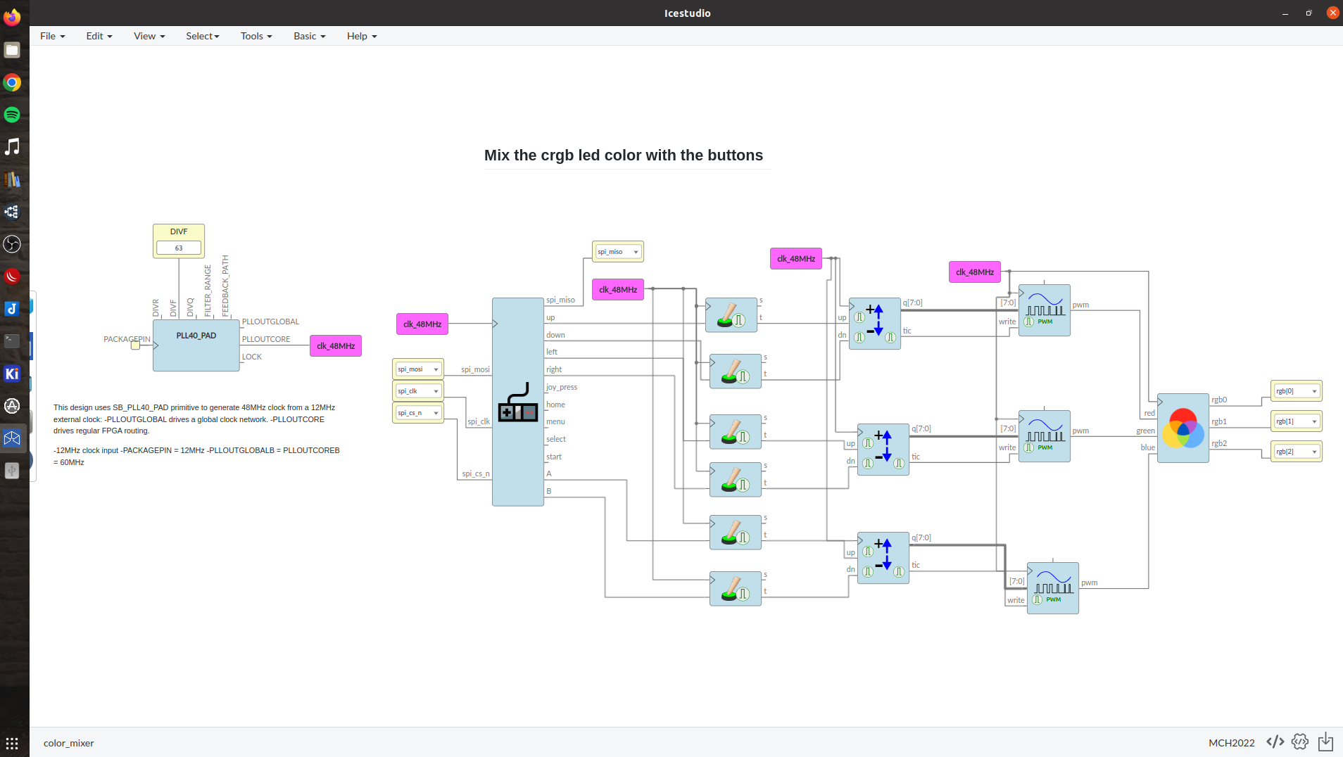
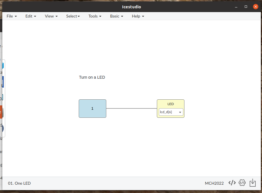
FPGA
Example FPGA code. A solution which is too fancy for my 6502.
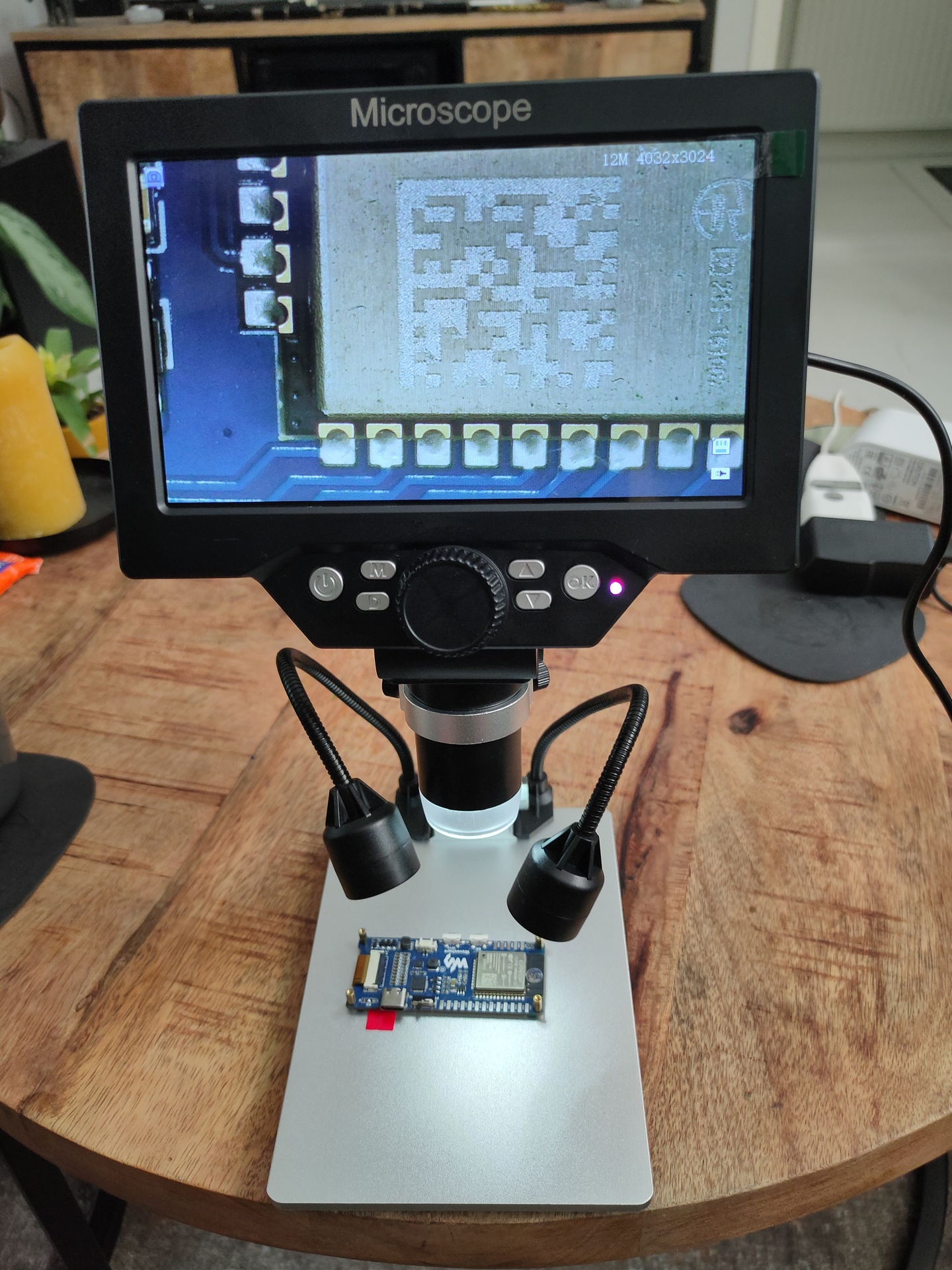
We are all getting older and electronics smaller. It’s hard to see if your soldering blobs are okay! Those blobs can reflect the light in a way that it’s not visible anymore to check them.
So i took Bigreds advice, and bought a G1200 Microscope. It’s a cheap but helpfull little gadget.
1-1200 times zoom
7inch screen (720p)
SDcard
Lipo battery
Recording on micro sdcard in 12 mega pixels pictures and 1080P Video. (even got a timer)
Focus button, and extra lights (There is a light source in de camera head, which can be adjusted by a knob)
When connecting to your pc, you get 3 options
PC Camera ( … so you can record using your pc with for example OBS)
Mass Storage, to read the SDCARD
Rec_mode ?!? – No idea yet
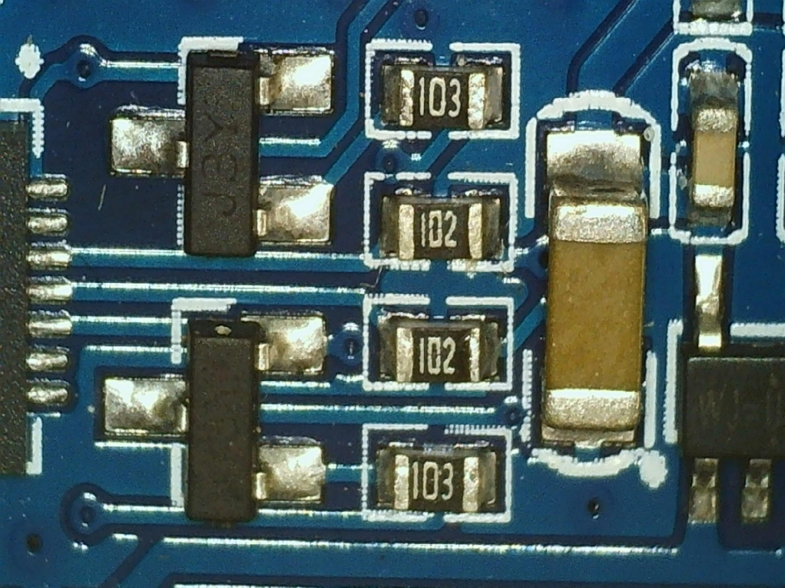
Below some examples:
Picture example
Video example
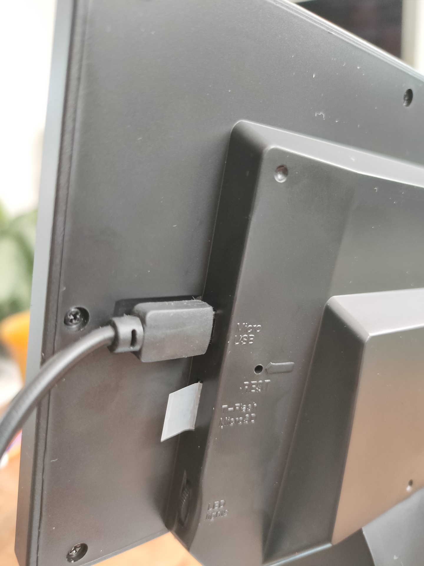
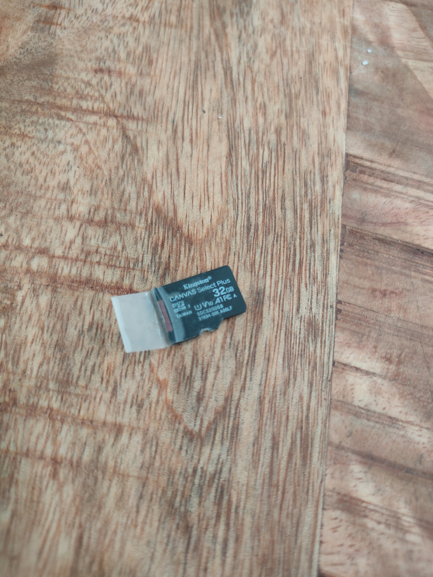
SDCard Access:
Access to the sdcard is a little hard. Connecting via Mass Storage is a solution. But i’ve put a little piece of tape to get the card in or out of the slot.
You can view the recordings on the Microscope itself. So i was wondering, can it play any other movie files?
I placed different MOV files on the sdcard, but the microscope skipped the ones i places on the sdcard myself.
I started to look at the metadata, and saw a Codec ID “qt 2016.04.21 (qt )”
 mediainfo VID_001.MOV
General
Complete name                            : VID_001.MOV
Format                                   : MPEG-4
Format profile                           : QuickTime
Codec ID                                 : qt   2016.04.21 (qt  )
File size                                : 551 MiB
Duration                                 : 12s 0ms
Overall bit rate                         : 385 Mbps
Encoded date                             : UTC 1904-01-01 00:00:00
Tagged date                              : UTC 1904-01-01 00:00:00

Video
ID                                       : 1
Format                                   : AVC
Format/Info                              : Advanced Video Codec
Format profile                           : Main@L4.1
Format settings, CABAC                   : Yes
Format settings, ReFrames                : 1 frame
Codec ID                                 : avc1
Codec ID/Info                            : Advanced Video Coding
Duration                                 : 12s 0ms
Source duration                          : 12s 360ms
Bit rate                                 : 14.5 Mbps
Width                                    : 1 920 pixels
Height                                   : 1 080 pixels
Display aspect ratio                     : 16:9
Frame rate mode                          : Constant
Frame rate                               : 25.000 fps
Color space                              : YUV
Chroma subsampling                       : 4:2:0
Bit depth                                : 8 bits
Scan type                                : Progressive
Bits/(Pixel*Frame)                       : 0.280
Stream size                              : 20.8 MiB (4%)
Source stream size                       : 21.3 MiB (4%)
Language                                 : 33
Encoded date                             : UTC 1904-01-01 00:00:00
Tagged date                              : UTC 1904-01-01 00:00:00
mdhd_Duration                            : 12000

Audio
ID                                       : 2
Format                                   : PCM
Format settings, Endianness              : Little
Format settings, Sign                    : Signed
Codec ID                                 : sowt
Duration                                 : 12s 0ms
Source duration                          : 12s 288ms
Bit rate mode                            : Constant
Bit rate                                 : 128 Kbps
Channel(s)                               : 1 channel
Channel positions                        : Front: C
Sampling rate                            : 8 000 Hz
Bit depth                                : 16 bits
Stream size                              : 188 KiB (0%)
Source stream size                       : 192 KiB (0%)
Language                                 : 33
Default                                  : Yes
Alternate group                          : 1
Encoded date                             : UTC 1904-01-01 00:00:00
Tagged date                              : UTC 1904-01-01 00:00:00
Tried to change this with ffmpeg, but it would not change the way i want.
ffmpeg -i VID_002.MOV -c copy -map 0 -brand 'qt   2016.04.21 (qt  )' VID_007.MOV

mediainfo VID_007.MOV
General
Complete name                            : VID_007.MOV
Format                                   : MPEG-4
Format profile                           : QuickTime
Codec ID                                 : qt   0000.02 (qt  )  <--------------- nope
Header of the movie clip maybe i have to look into this … later