Last Updated or created 2022-08-23
UPDATE: 20220823 Sid working
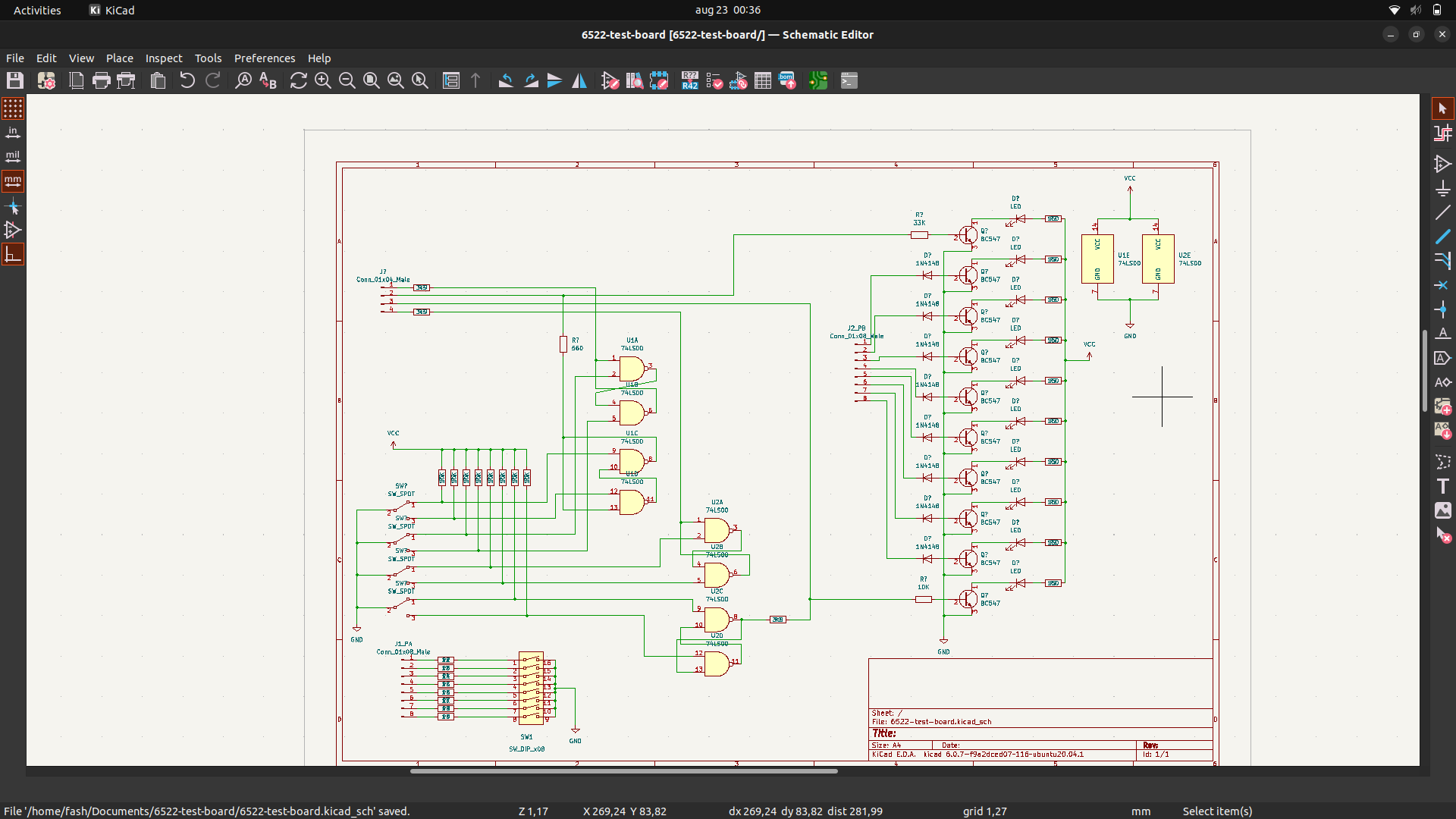
Above is my Kicad design (reverse engineering print below, which was made for my 6802CPU, which i could use to test the 6822 PIA)
The 6822 is simular to 6502 in design. So i’m going to redo this for my 6502.
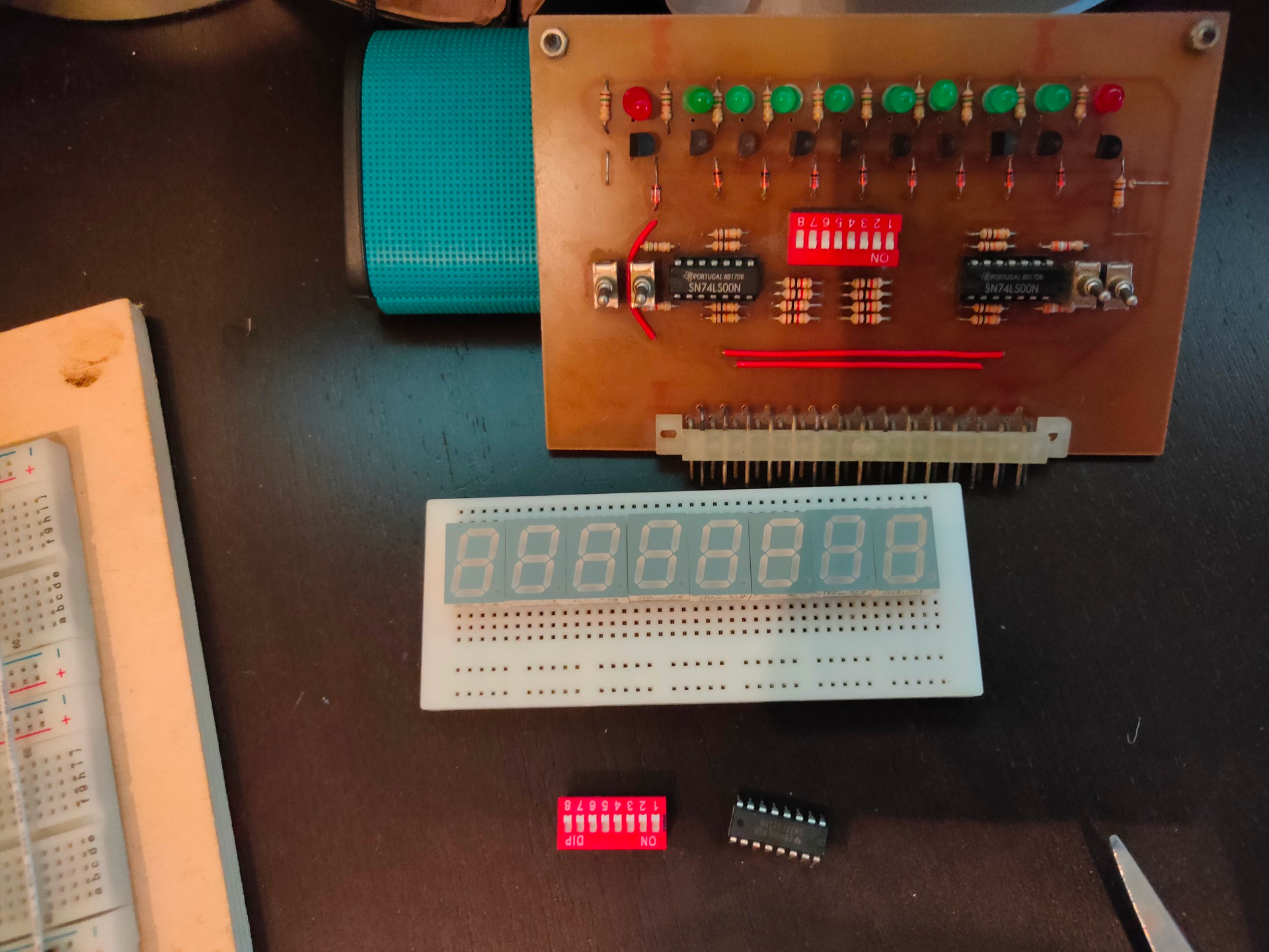
The 7 segment displays are a start of hex-keyboard/display combo i’m going to post more of in the next days.
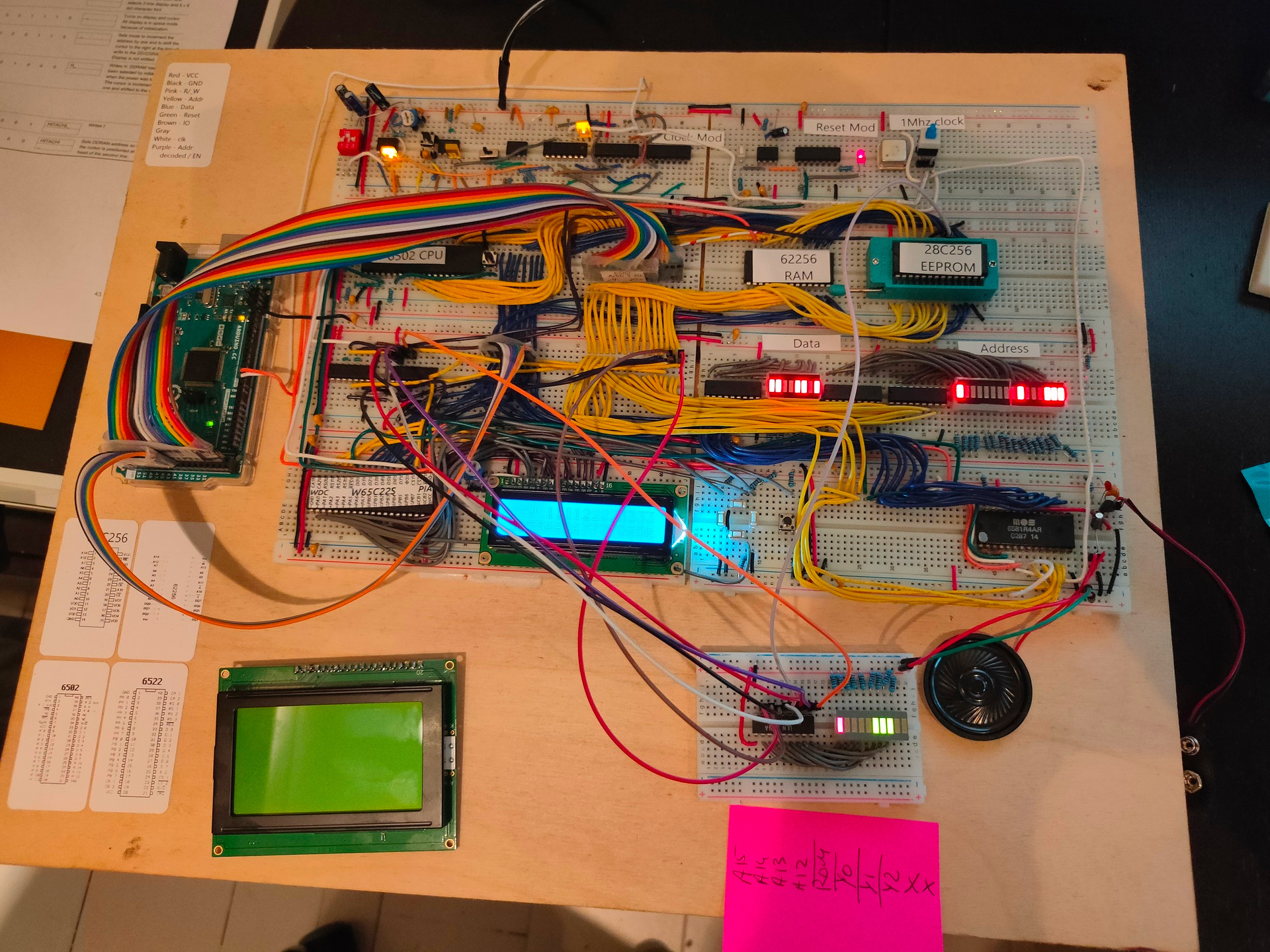
Below a part of the rom for the LCD dual line display.
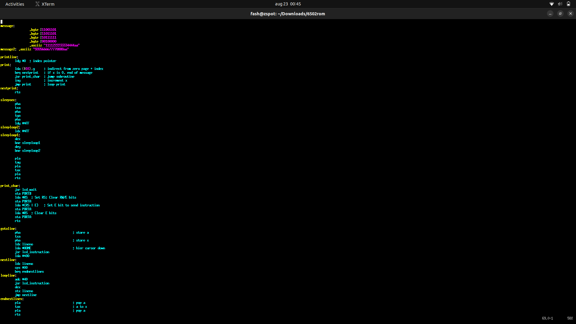
Started to write routines which i can call to manipulate the display. Setting the pointer to a message, setting the line to use and a subset of controlls like: Center, Right, binary to ascii, scrolling, etcetera
        lda #0             ; set line number
        sta lineno         ; store
        jsr gotoline       ; goto line in display
        lda #<message      ; get address from message and store for printline subroutine
        sta messagestore
        lda #>message
        sta messagestore+1
        jsr printline      ; print

        lda #1  ; set line number
        sta lineno      ; store
        jsr gotoline
        lda #<message2
        sta messagestore
        lda #>message2
        sta messagestore+1
        jsr printline
Above additions:
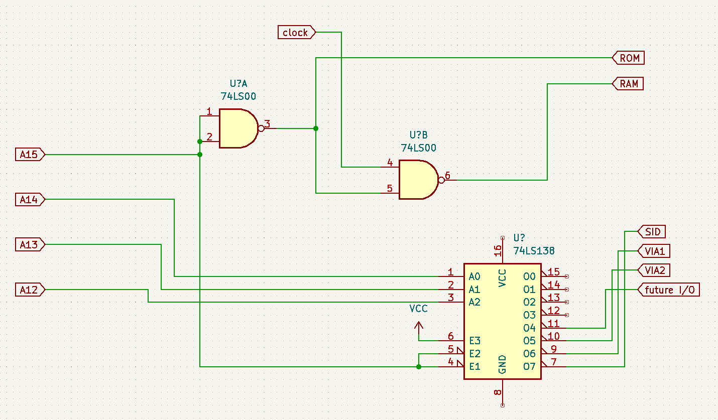
New address decoder
Below left the new graphical display, below right a test board which shows address lines and decoded chip-enable lines.
A15 high -> ROM
A15 && A14 low -> RAM
combination of A15 low and A14 high – A13 and A12 wil select peripherals.
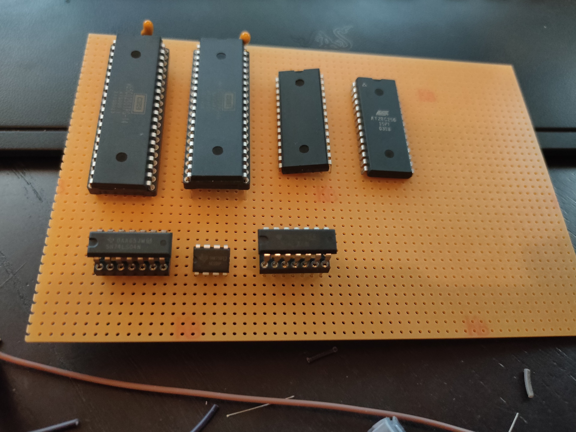
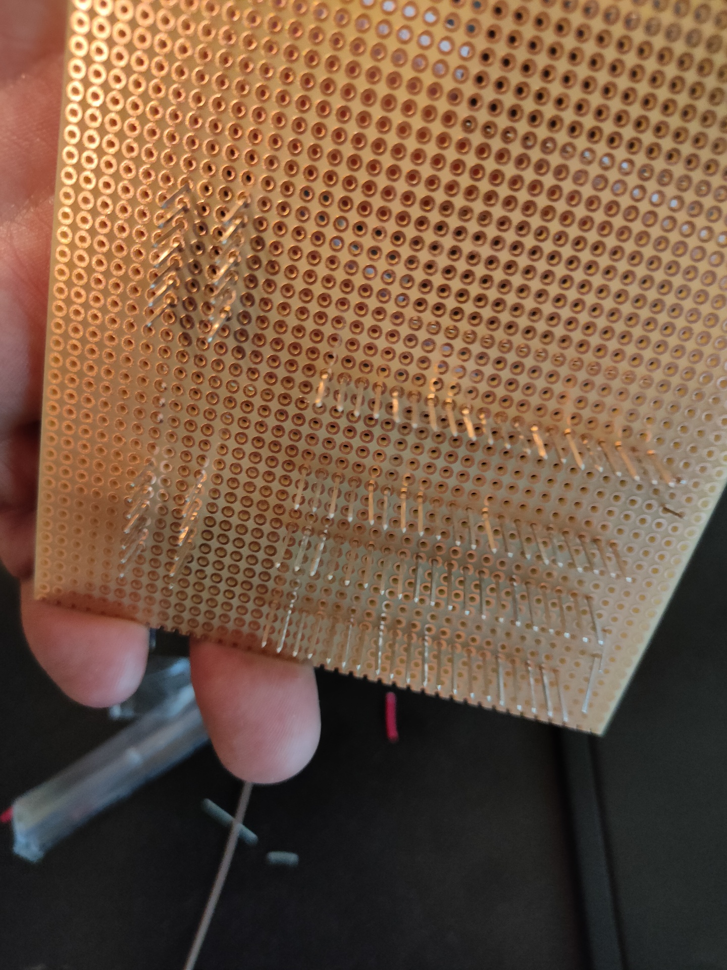
Above is a start of a wirewrapped version, i also started a PCB design in KIcad that will continuously be changed as i alter designs.
UPDATE SID Working! Using new address decoder.
SID = $7000

makesound:
	lda #0
	sta SID+$5 ; Channel1 - attack/decay

	lda #250
	sta SID+$6 ; Channel1 - Sustain/Release

	lda #$95
	sta SID+$0 ; Channel1 - Frequency low-byte

	lda #$44
	sta SID+$1 ; Channel1 - Frequency high-byte

	lda #%00100001
	sta SID+$4 ; SAW + Gate

	lda #$0f
	sta SID+$18 ; Volume max
