Deeply impressed by your blog content which means a lot to electronic enthusiasts.
I'd like to sponsor your project by providing free PCB prototyping,
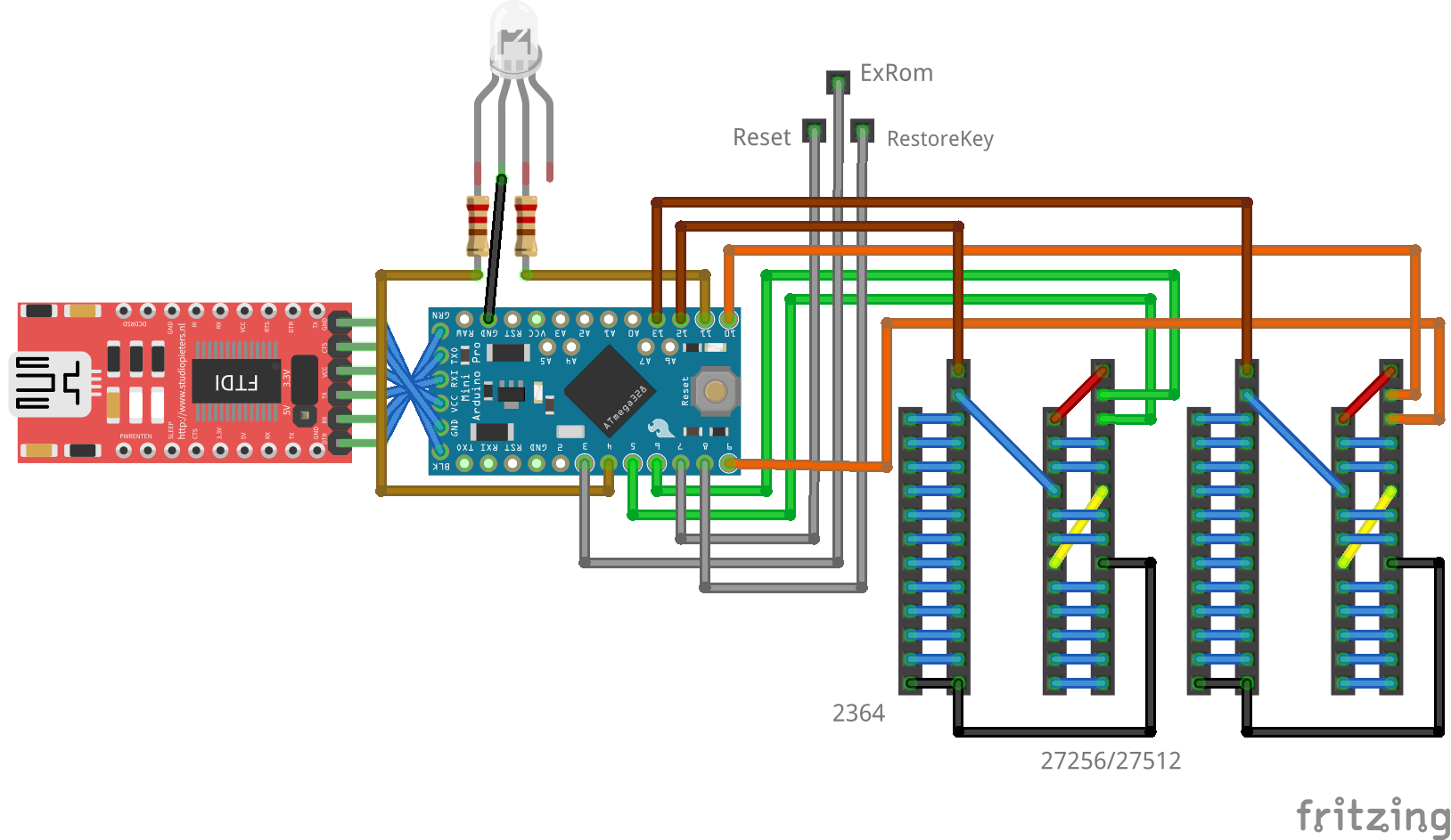
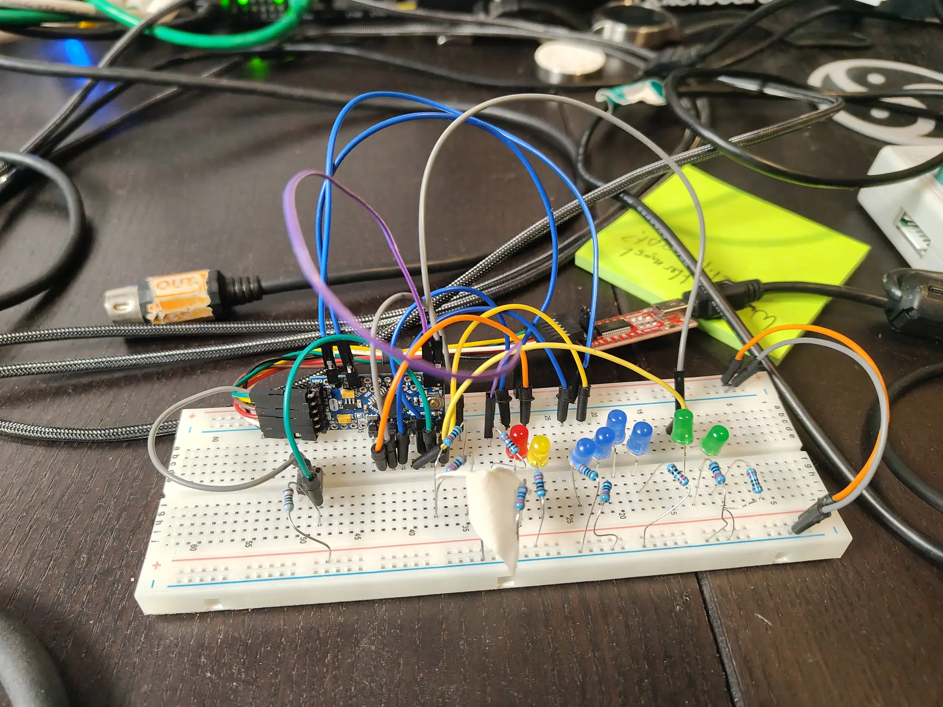
ROM SWITCHER
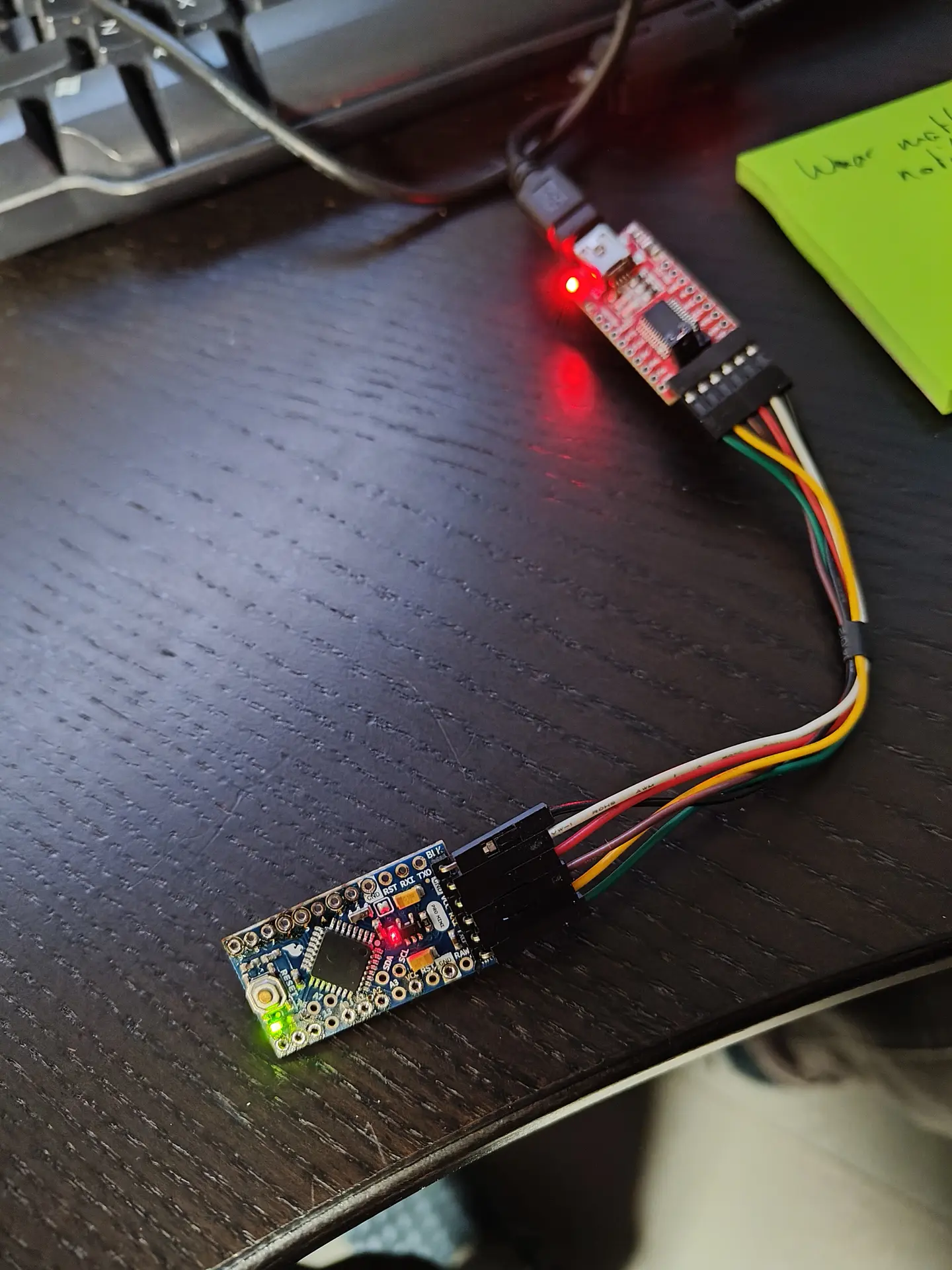
I made a rom switcher in the past. Now I’m using an Arduino to switch Kernal and Character rom. (Partly idea from Adrian)
Where the F* is my schematic. Ah here it is.
Above right picture:
Tactile button (emulates restore key)
Red led – reset
Yellow led – Exrom
Blue leds, Address lines select ROM part in 27512 EPROM
Green leds, Address lines select ROM part Character ROM
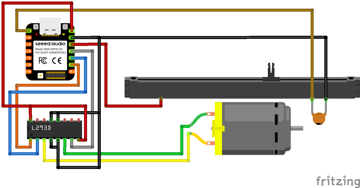
Motorized Fader Potentiometer
I don’t trust some B&B’s so I made a camera detector. (I always scan the wifi and Access Points) This one lets you know if there are IR enabled camera’s. (Night vision)
Picture 1:
1 = org camera module, IR filter is hard to remove. (See pink color)
2 = other module, IR filter is at bottom
3 = IR Filter, I removed this.
Picture 2:
IR light blast from a “hidden” camera. (I need to adjust focus of lens)
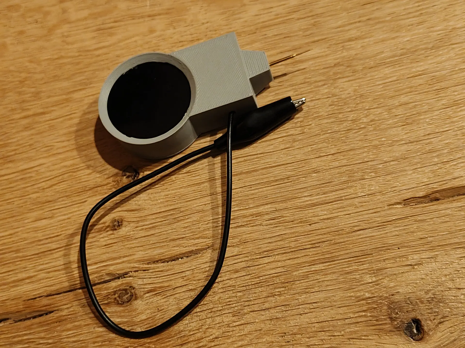
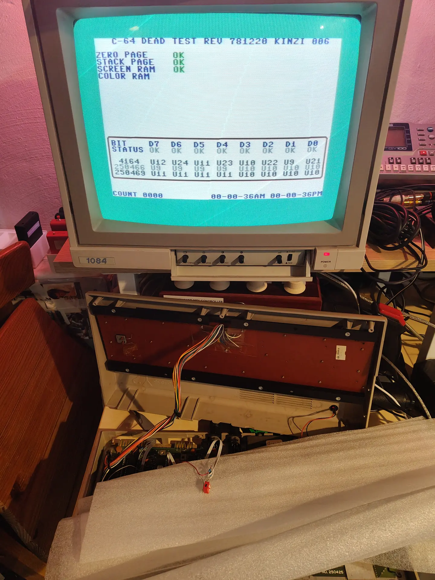
While I made this for my Commodore C64, it is applicable for many things.
It started with some cheap displays from Ali, and some leftover Wemos D1 from my Pressure Lab project.
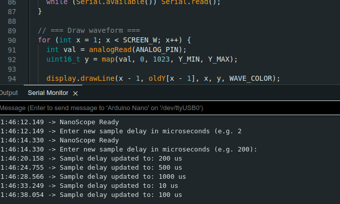
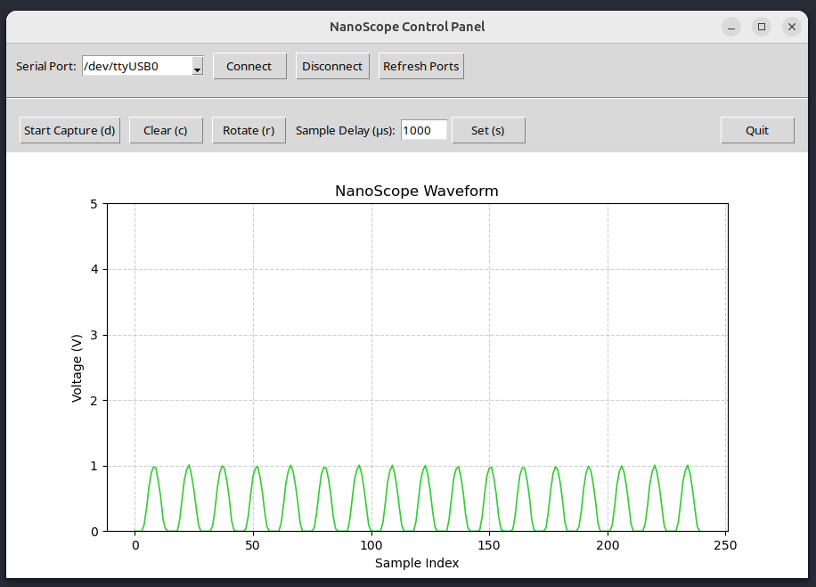
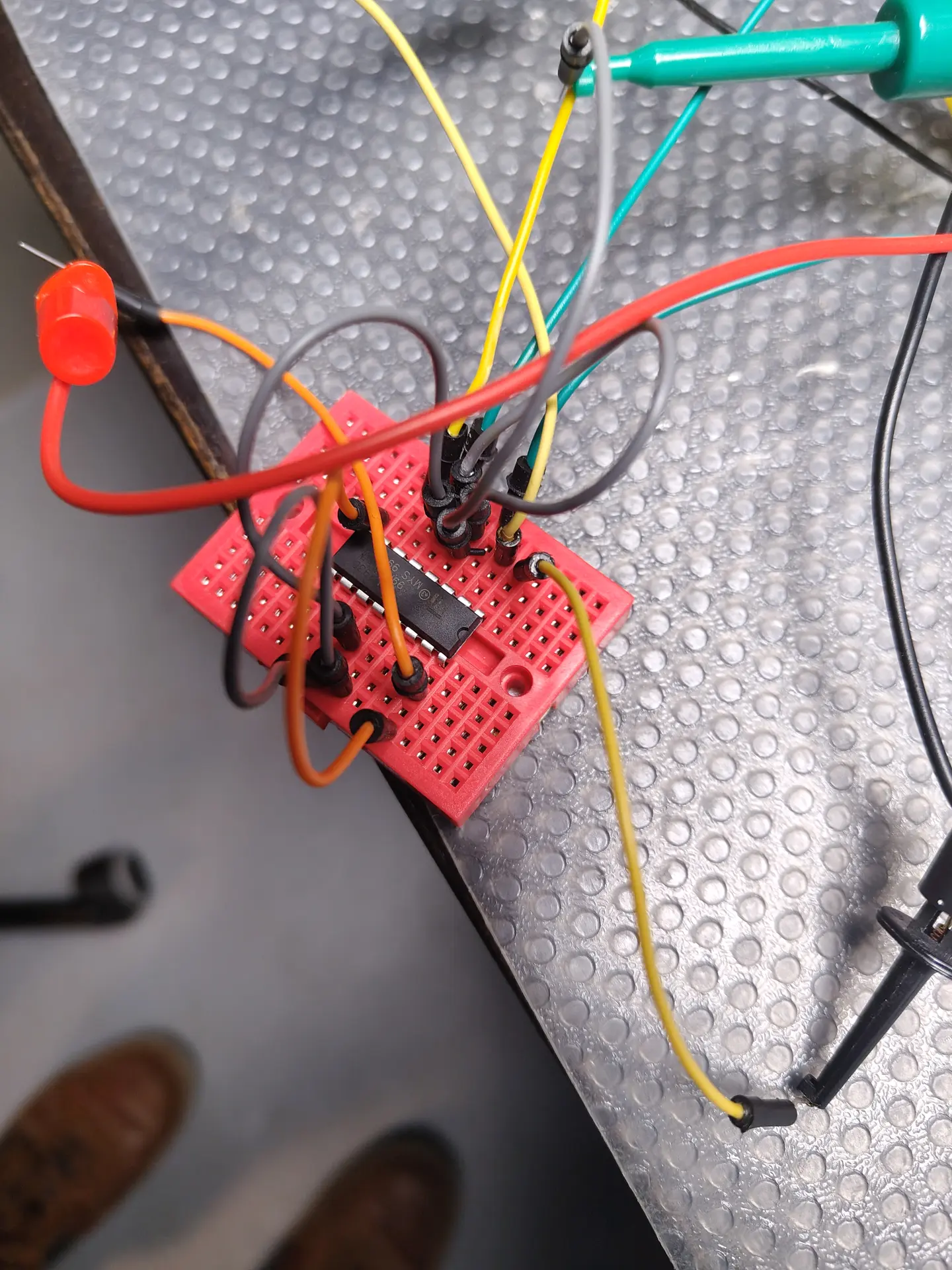
I Started measuring the audio output from sound devices and from my C64. I soon discovered that I needed some way to get the offset and amplification correct for the analogue input of a Wemos. (0-3v3)
So a little op-amp circuit was born, but not without some struggles. I forgot many things about amplifiers. It was one of the first school books I got rid of. (Sorry mister Rafaela)
After searching the internet and posting a question on Reddit I ended up with the following.
R1 and R2 are 100M. The potentiometer P1 allows me to set the offset. R3 is 1M C1 is 100nF to decouple the audio signal from the RCA.
R4 is 47K and C2 is 330nF (thanks tycho205) Cimportant=1/(2πfR2) where f is the lowest frequency of interest. In this case Cimportant should be about 330nF
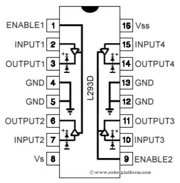
LM324 is a quad amplifier, leftover from another project. Note, the SINGLE RAIL power.
P2 potentiometer is 2M (leftover) and gives me a variable amplifying opportunity.
A = Audio input
B = Setting the offset with P1
C = Setting the amplification
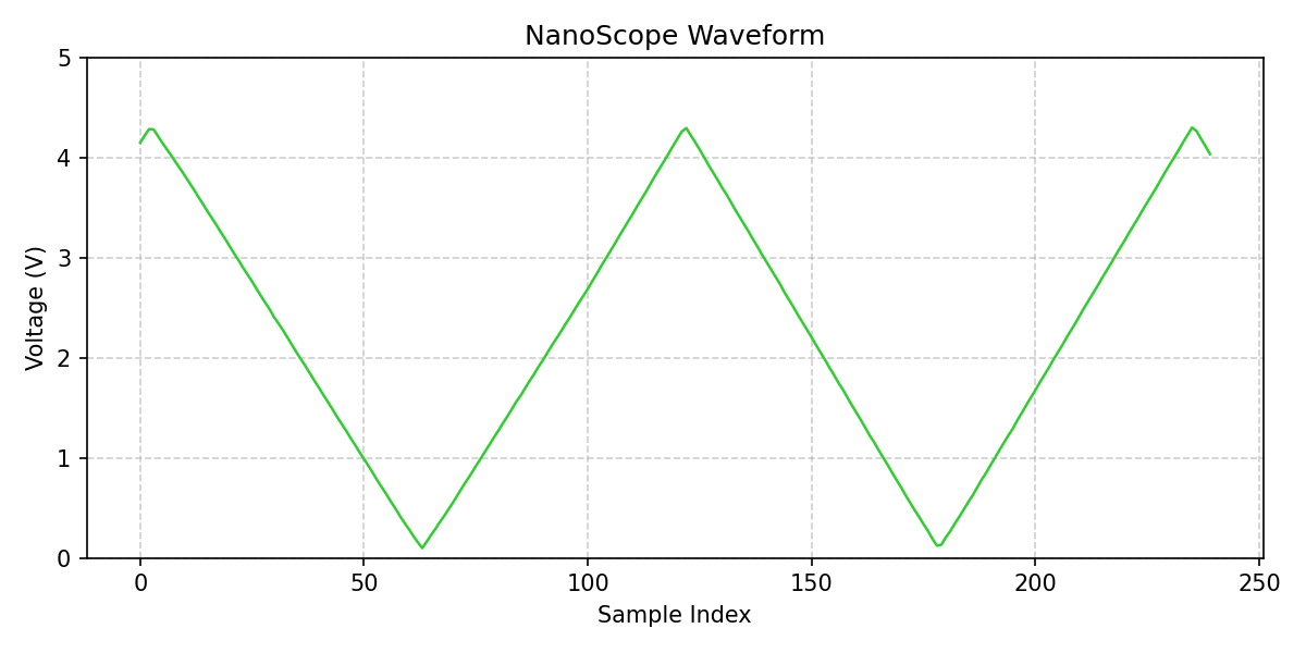
Below input signal (note negative values) above amplified signal with offset!
The displays are 3 Wemos controllers with a cheap I2C display. These are just fast enough to do FFT.
Analogue in is the output from the OP-amp offsetter ..
CODE
Needs cleaning up, and a better stabilize routine.
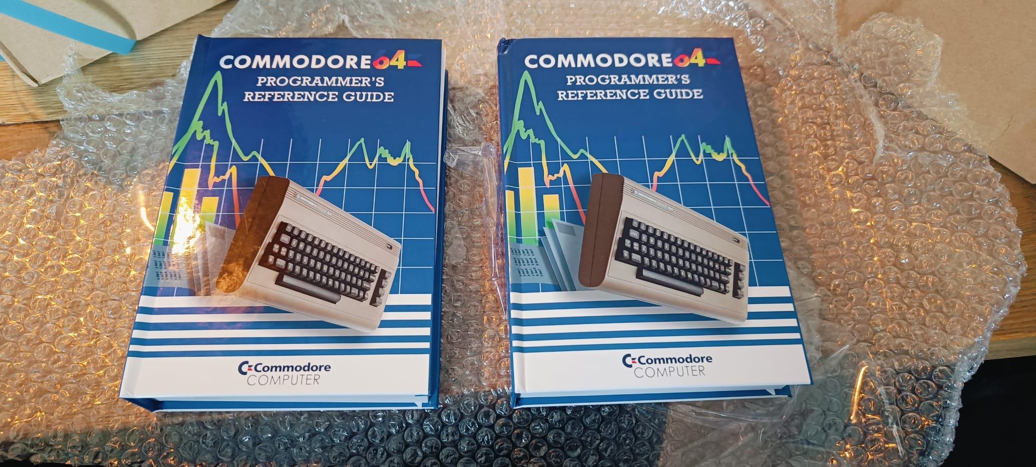
I’ve printed two books using the Lulu service. (One for Tyrone) When they arrived, I noticed some faults. Lucky Lulu will be printing them again for me.
The book has over 500 pages and has a nice hardcover.
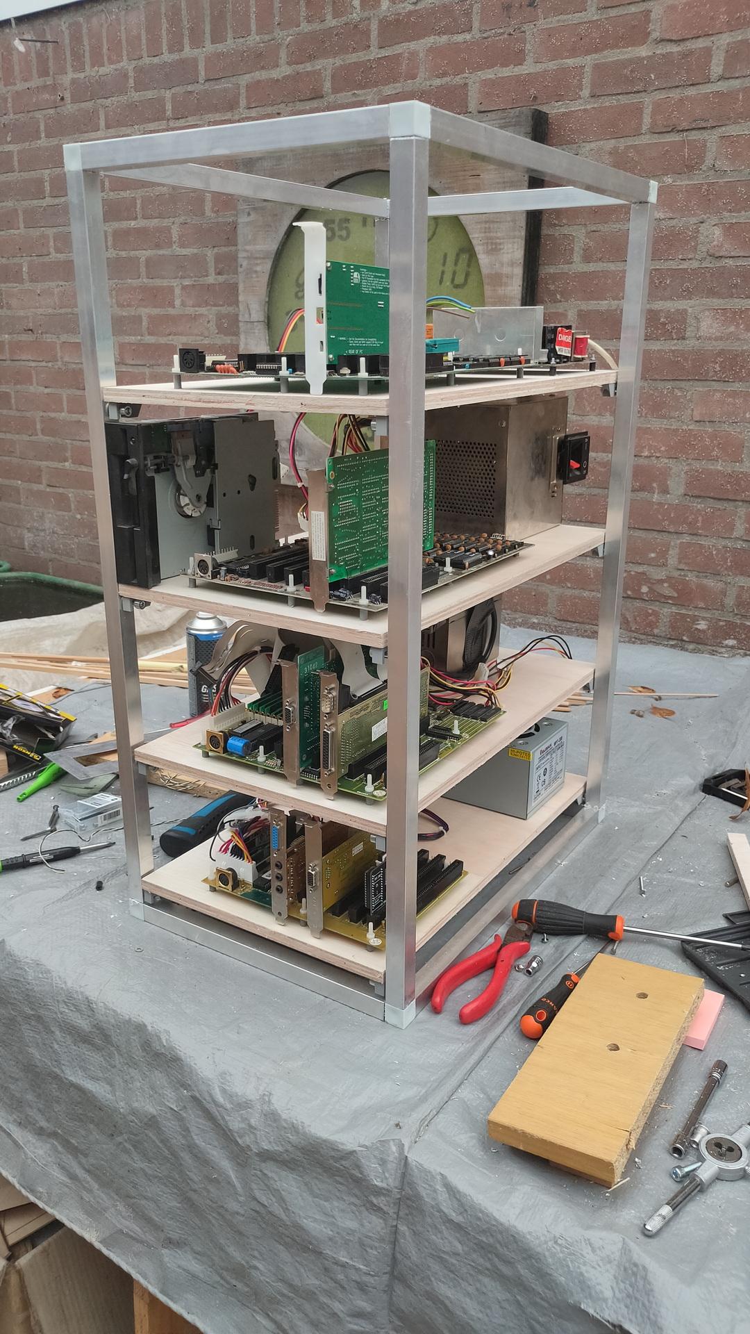
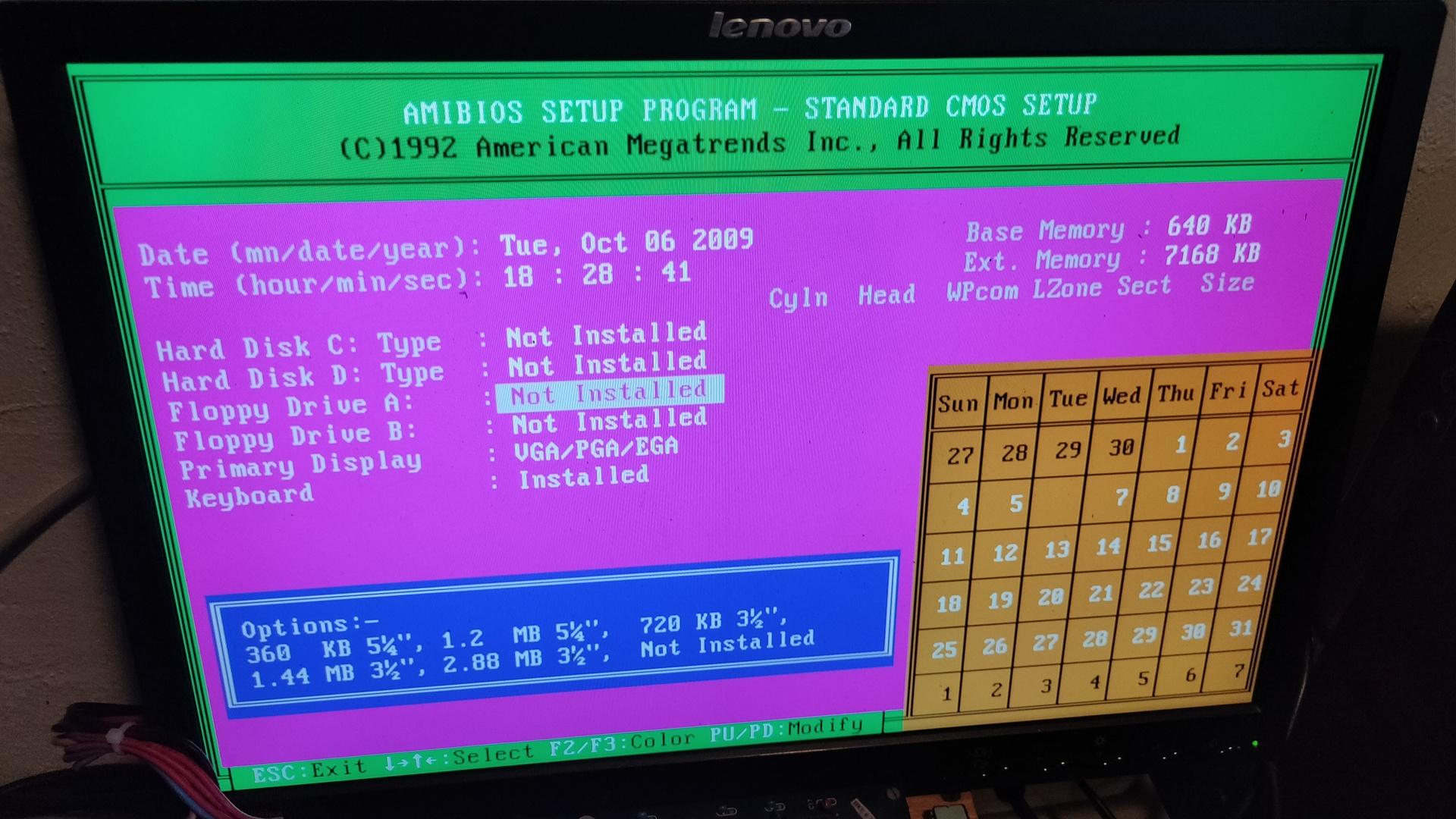
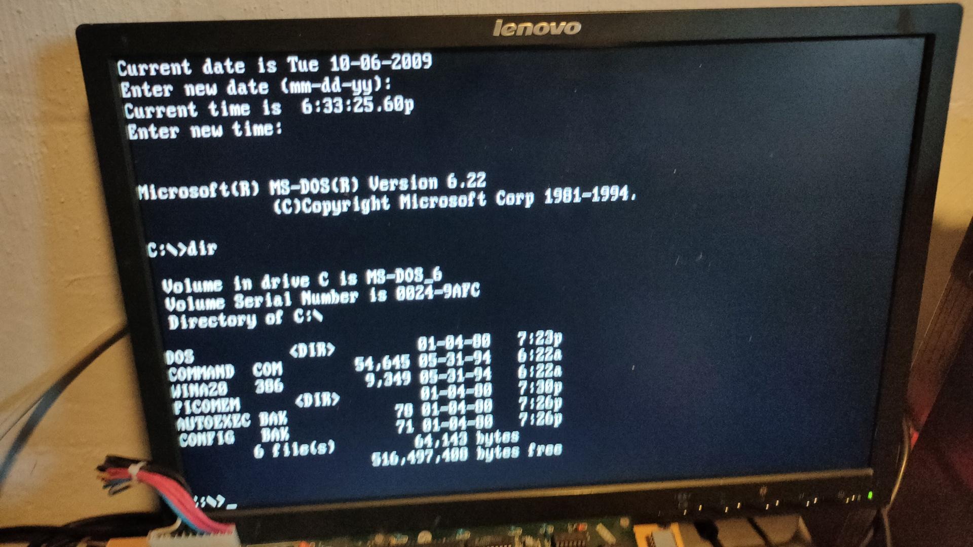
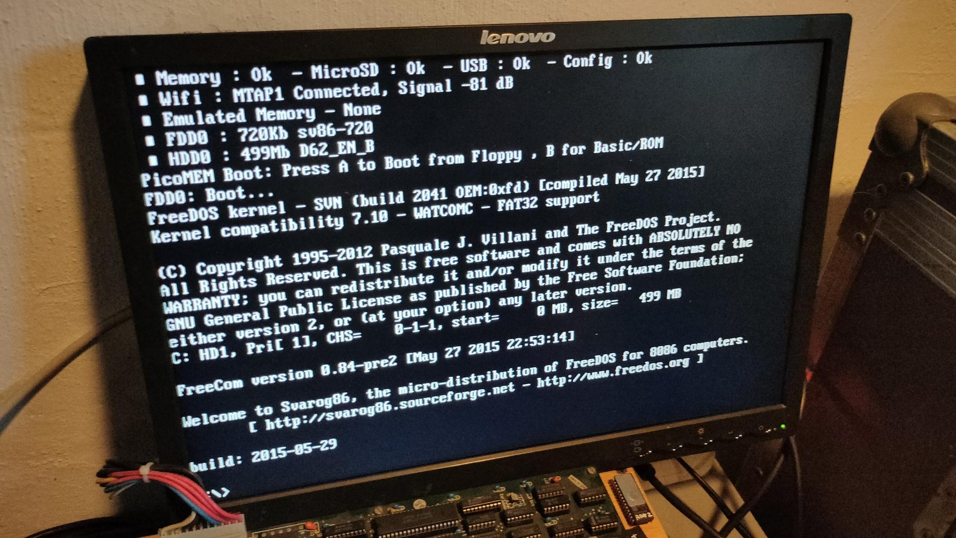
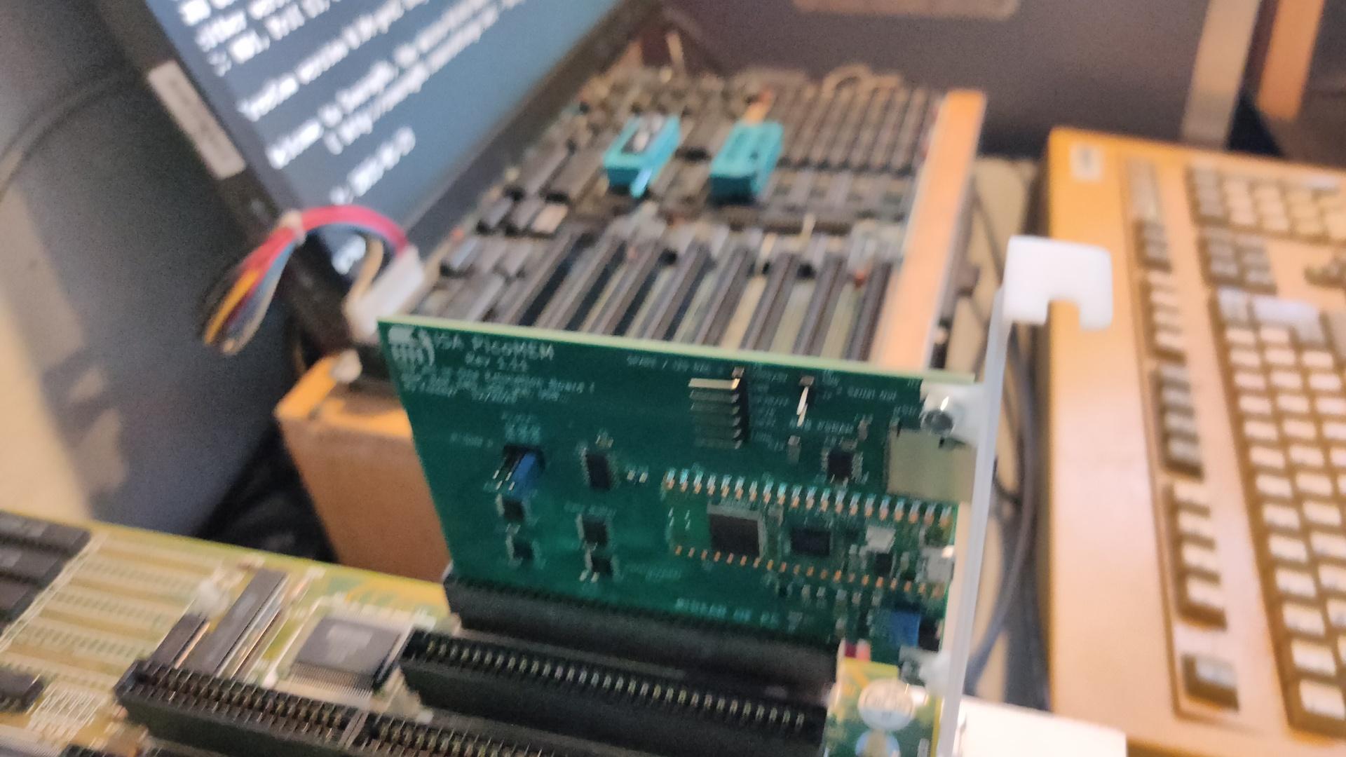
And I’ve been busy building a Mega Tower with 4 Motherboards. This will have a superb processing power! .. not. It houses some old motherboards for hardcore machine coding on real old hardware.
From top to bottom: 8088, 8086, 80386, 80484
Todo:
Rework on the cables
3D print an information plaque on the front of each board
Add a control panel on each board
Maybe some dust cover would be nice
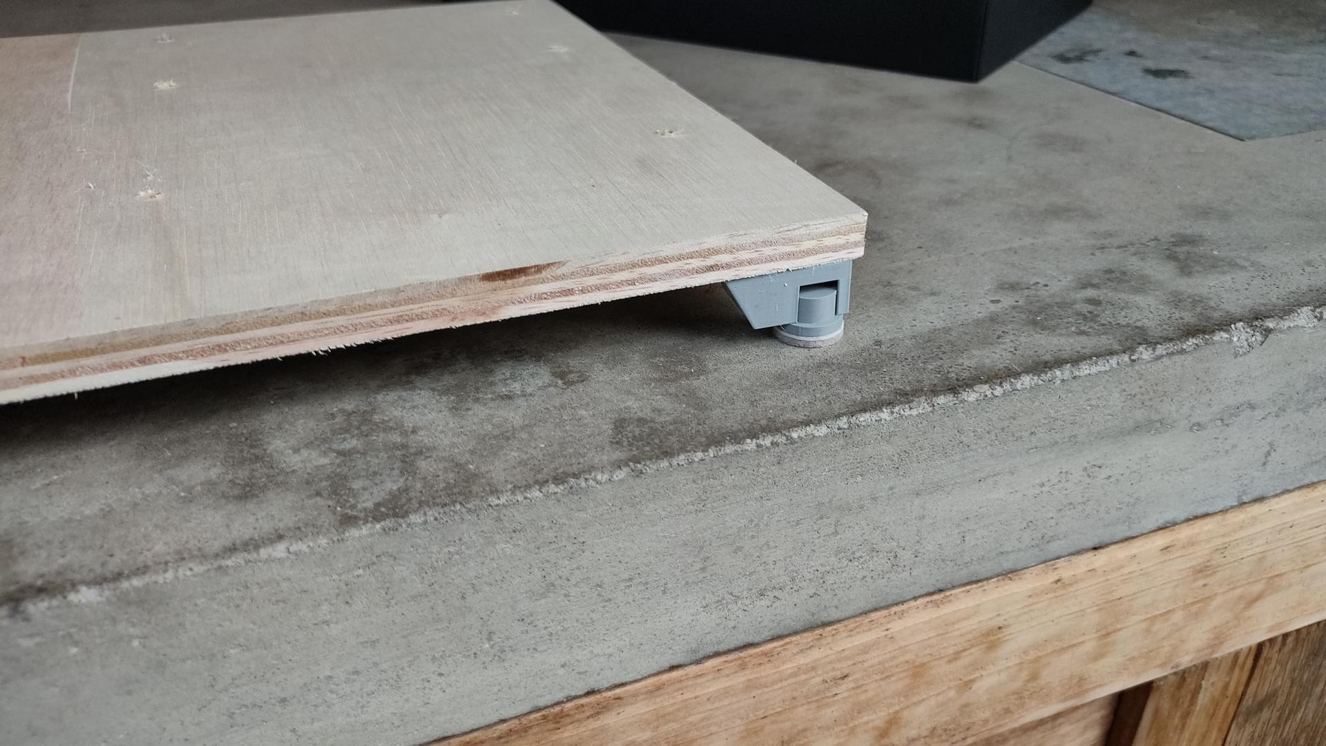
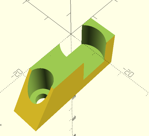
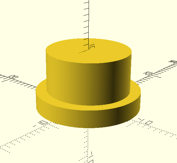
I can remove the boards, and place them on a table. I’ve made some custom feet for them. Twist and lock by my own design.
Padded feet
The openscad files:
The locking is done by making the cylinder slightly oval by 0.5mm
I’ve got two friends who make old retro computers.
They like to use old chips and use only THT.
What is my take on this?
I like to use THT when possible. Exceptions are:
Size constrains
No THT parts available
New gadgets
Old versus new chip solutions
CPU : never a new alternative (I’m not going to replace a 6502 using Arduino emulation, for example)
Yes, I’m using static ram instead of dynamic
Address decoder using 74xx ? Yes, I want to test at least once. But using a ATF22v10 has my preference. (Not using GALs anymore)
I only replace with newer alternatives when it does NOT interfere with how a system is performing. CPU has its own quirks, also chips like the SID. I never emulate when it can be avoided. Address decoding, RAM or ROM yes please 🙂 Old untrusted UV Eproms are sh*t. Give me the new flash-able alternatives any time
I can emulate everything, but I need real hardware.
Real 6502
Real 68000
Real 8088
Real 8086
Real 80386
I still want a real VGA monitor because I used to write VGA manipulation programs which only work on CRTs.
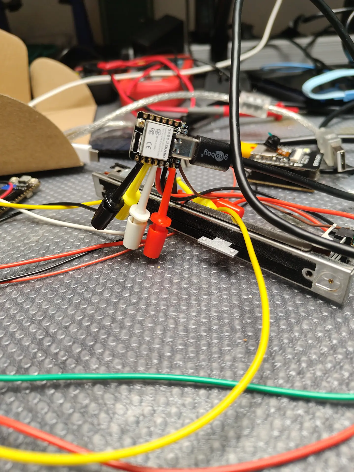
I’ve been busy programming Python and NodeRed for a client. But these are the things I’ve done in the last days.
C64 Assembly: Breaking borders, using sprites and multicolor font intro.
It does not look impressive, but I’ve learned a lot. Found a new way (for me) to open borders and change border colours on predefined raster lines. Sources will be posted.
KiCad tutorial, posted on YT also because I could not find many resources about the subject online. Maybe it’s helpful
Video editing using Kdenlive.
Edit: Even faster, use Netlabels, no need to join pins. Press L (uppercase) select pin 1, name 1. Press and hold insert until all pins named. Copy paste socket 5 times and goto your PCB tab.
This movie is about creating a backplane for a 6502 SBC I’m building. It is real-time and below 4 minutes.
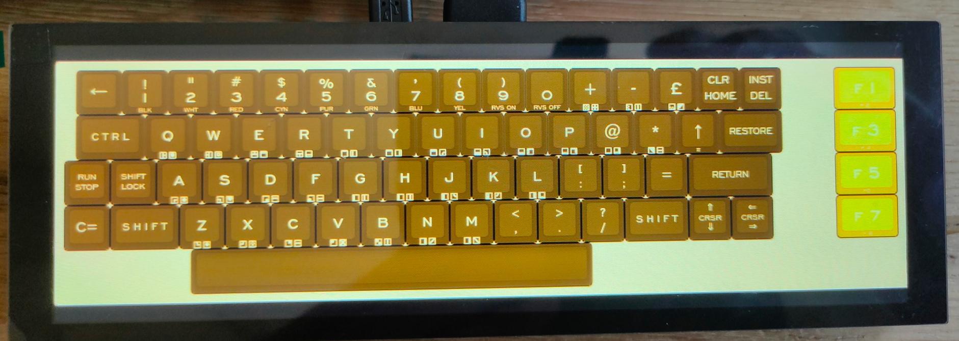
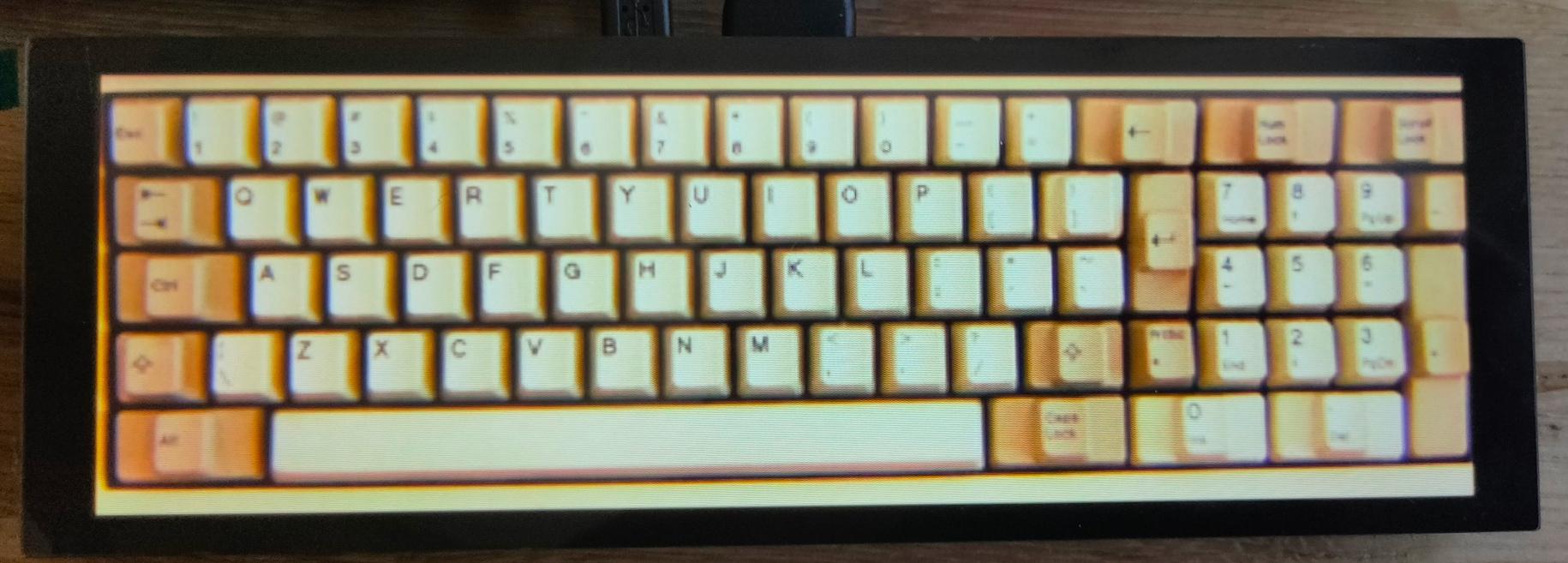
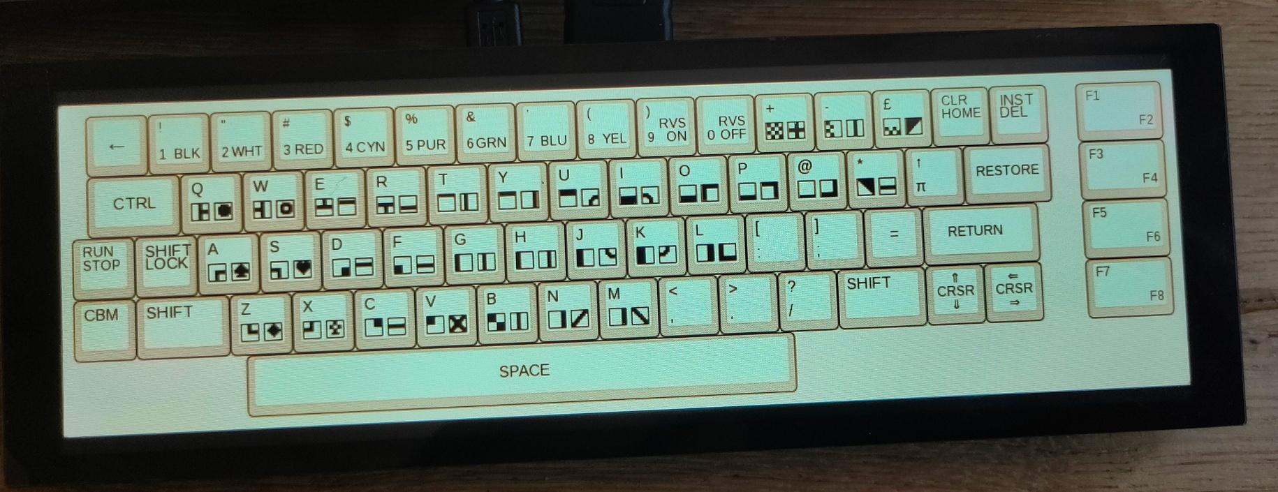
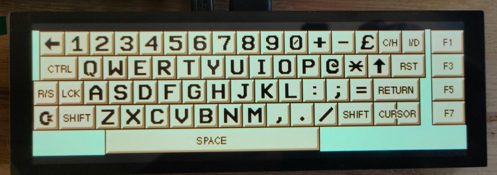
Multi Keyboard
My small multitouch screen came in. This is for my previously mentioned multi-computer case.
It is going to show multiple keyboard layouts for different systems. (See previous posts about this)
Waveshare display, Raspberry Zero as HID device, using USB and pin emulated keyboards. (c64 matrix, AT (DIN) keyboard, ps2 keyboard)
Some example screens
Vic-20
Photo-realistic
Petscii C64
Another C64
I’m also going to make a layout like the keyboards on my 8085
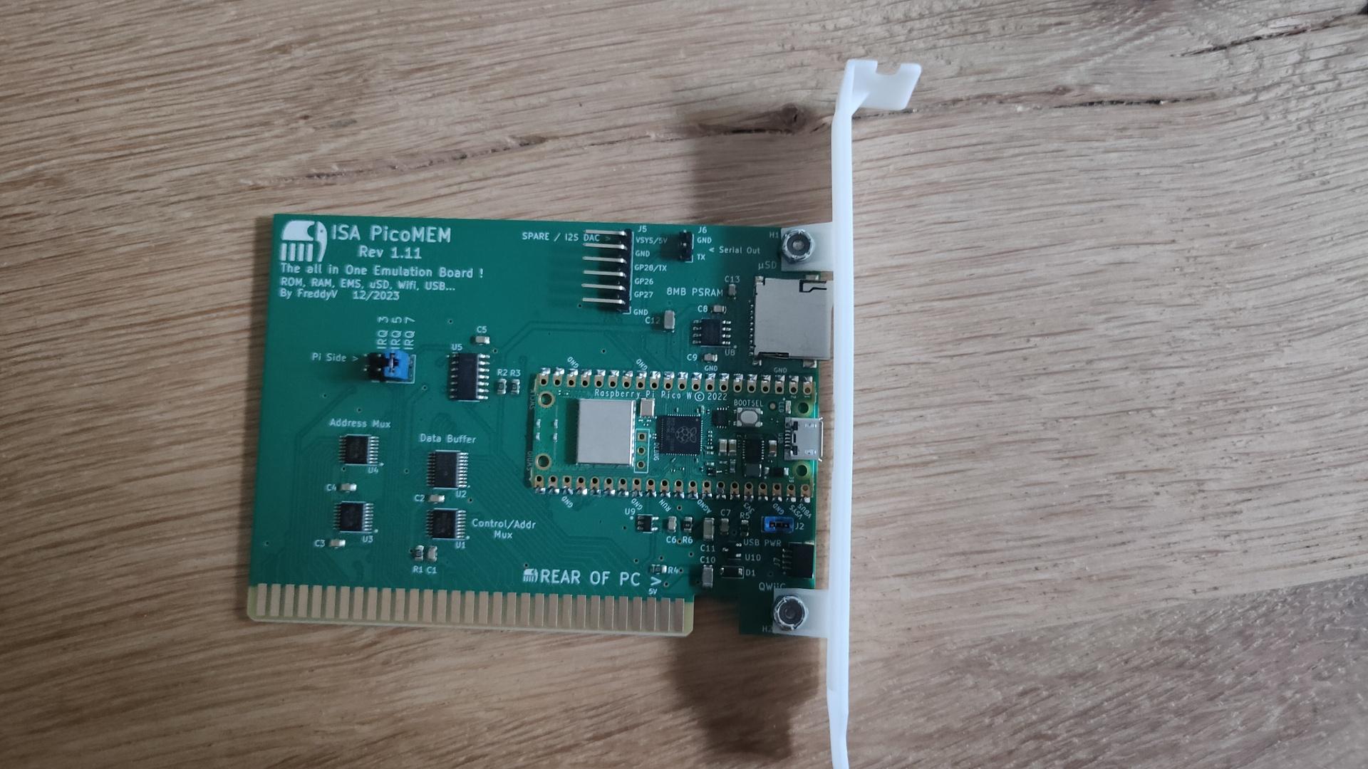
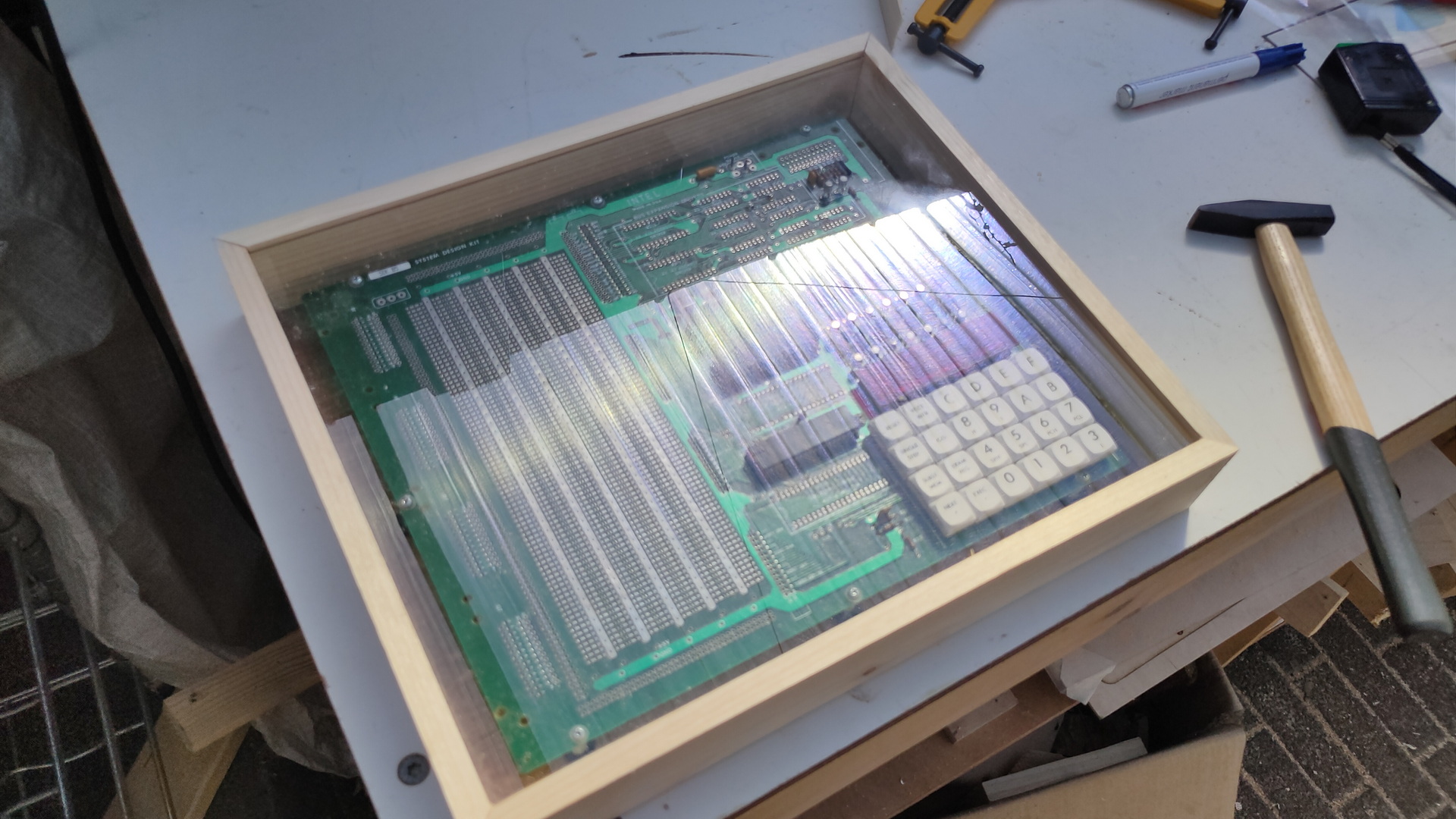
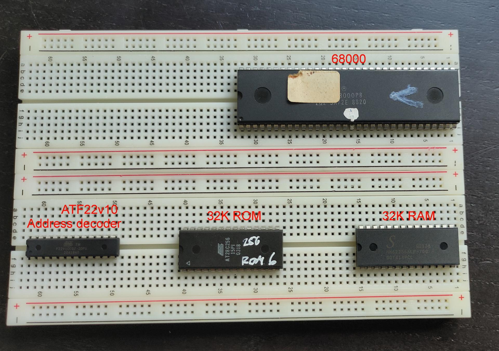
Started working on my breadboard version of a 68k computer. When it’s working, I’ll make a PCB version. Using almost only parts I still have. (No 8mhz crystal)
The 68000 being 24 bit address and 16 bit data needs 2x 8-bit roms and 2x 8 bit ram, but i didn’t have the components yet in this picture.
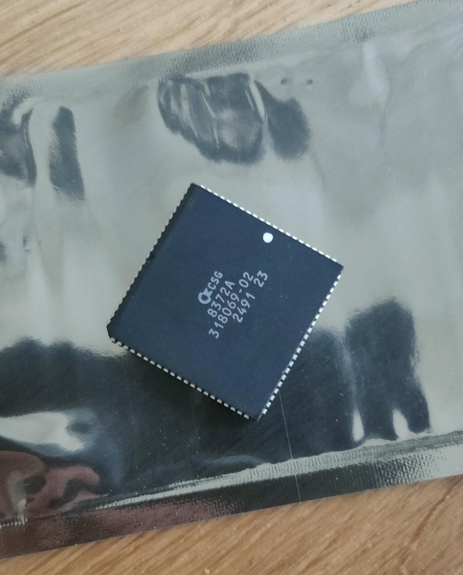
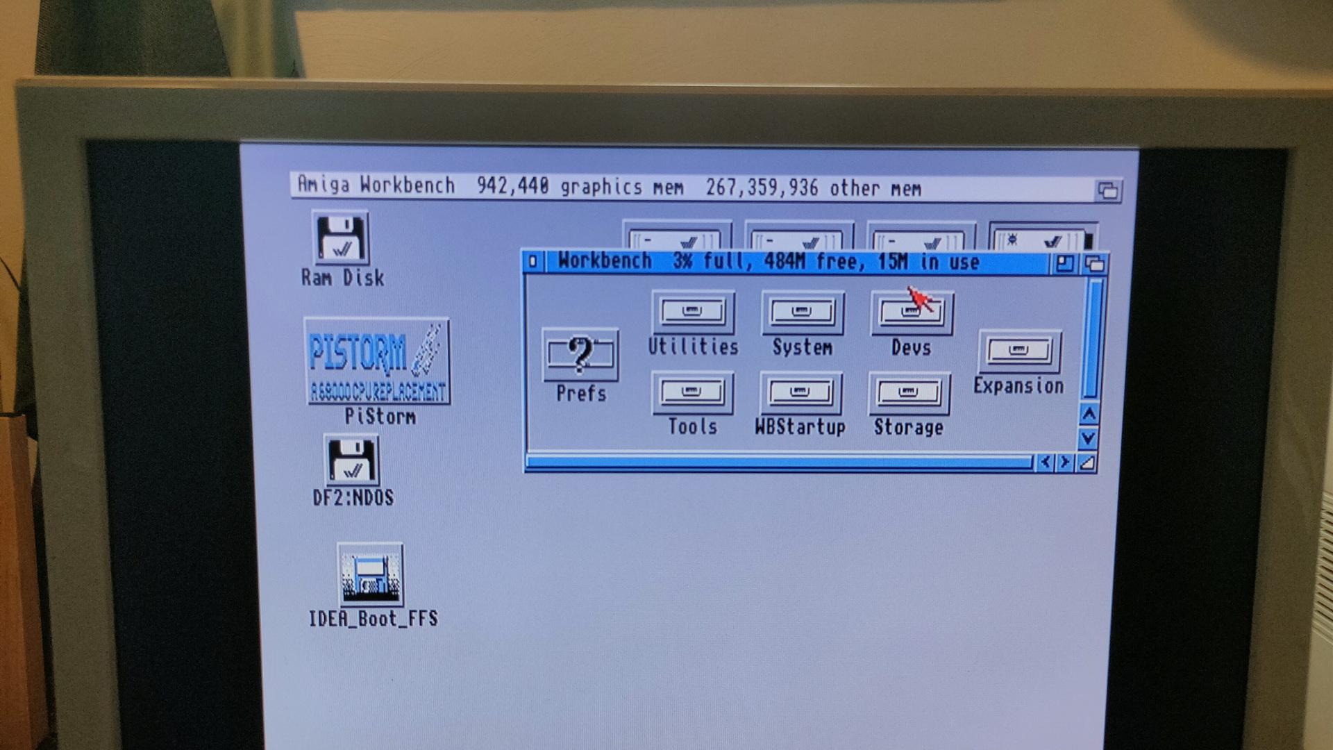
While tinkering with above, my Fatter Agnus chip came in.
To make a 1mb chipmem version of your rev 5 amiga (PAL)
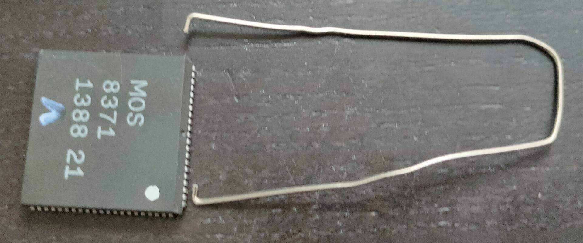
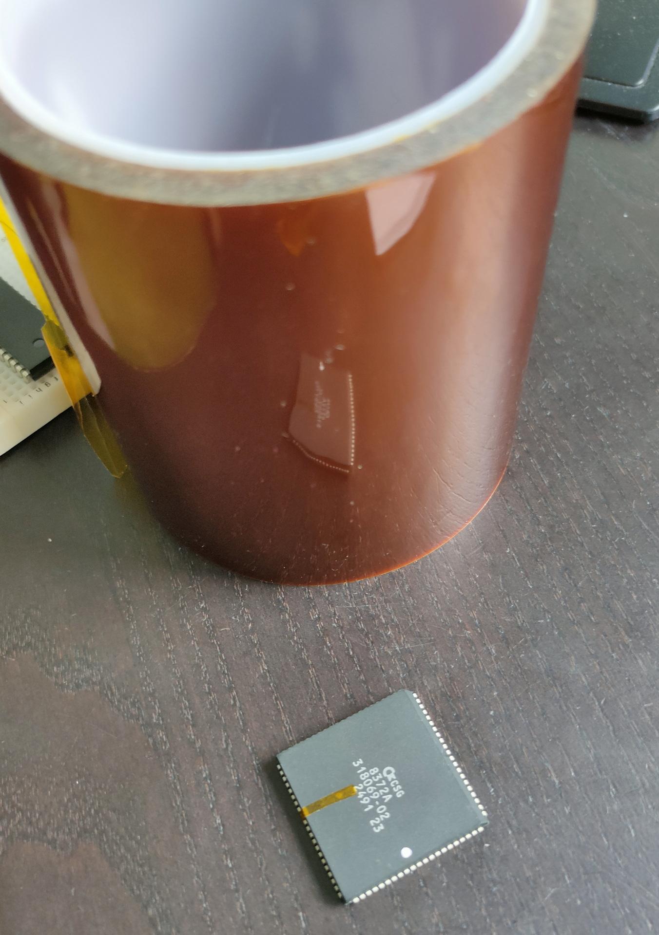
You need to have a newer version of the Agnus chip (I had 8371, and bought a 8372a) AND you need a 512kb trapdoor memory expansion.
An unmodded rev 5 will see 512kb Chip mem and 512 Fast mem.
Replacing the Agnus 8371 for 8372a: I lost my PLCC puller, so I modded a paperclip into a puller 🙂
MISSING IN ACTION
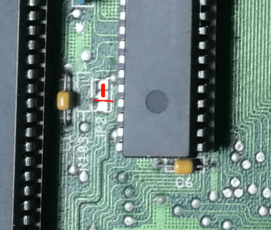
When placing the new chip, I had to tape pin 41 for PAL version. I used Polyimide Film tape.
Next I had to cut the jumper 2 connection and solder the other pads. (Bottom and middle disconnect and middle and top bridged)
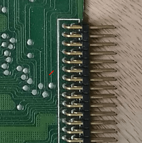
Next was another cut on the PCB, this disables the trapdoor card detection.
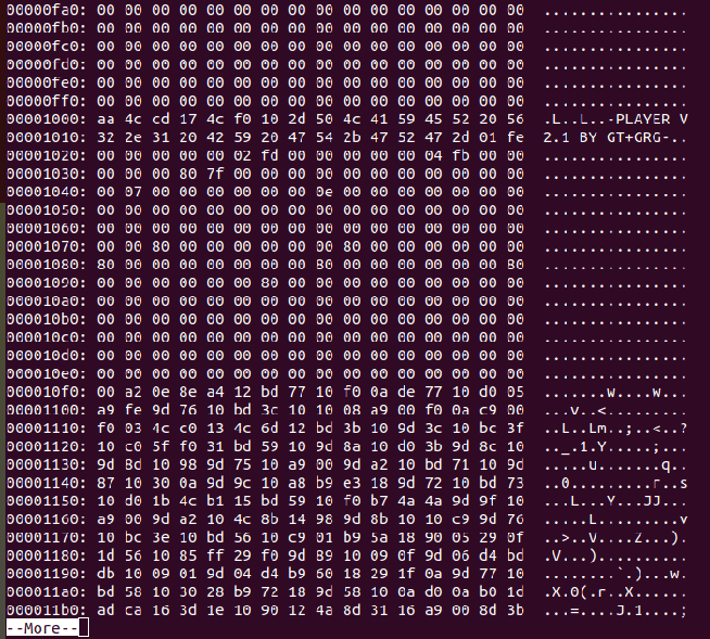
Re-learning the little I knew (I never had a c64 as a kid). Back to basics, welll machine code I mean.
Programming a little demo using acme. Split screen bitmap and text mode plus sid music
Running a little demo in retrodebugger (missing the sid music in the recording)
Some useful commands
; Dump prg with offset 0x800 per byte and skip 00 00 lines xxd -o 0x800 -g1 icecrew.prg | uniq -f10
; Write symbol list acme -l icecrew.sym icecrew.asm
; png to kla (koala picture) retropixels icecrew.png -o icecrew.kla
; relocate a sid address sidreloc -r org.sid new.sid
Below code has some flaws:
Many empty gaps, creating a large file. Exomizer could fix this, but better memory management should be the better solution. The Koala file has many 0 bytes, the logo is small but the file is created for a full screen image.
Part of the program see $1000 of start of SID music
!cpu 6502
!to "icecrew1.prg",cbm

; Standard basic sys runner
basic_address   = $0801

; sid addresses
; address moved using
; sidreloc -r Lameness_Since_1991.sid lame.sid
; addresses found using
;sidplay2 -v lame.sid
;+------------------------------------------------------+
;|   SIDPLAY - Music Player and C64 SID Chip Emulator   |
;|          Sidplay V2.0.9, Libsidplay V2.1.1           |
;+------------------------------------------------------+
;| Title        : Lameness Since 1991                   |
;| Author       : Peter Siekmann (Devilock)             |
;| Released     : 2017 Oxyron                           |
;+------------------------------------------------------+
;| File format  : PlaySID one-file format (PSID)        |
;| Filename(s)  : lame.sid                              |
;| Condition    : No errors                             |
;| Playlist     : 1/1 (tune 1/1[1])                     |
;| Song Speed   : 50 Hz VBI (PAL)                       |
;| Song Length  : UNKNOWN                               |
;+------------------------------------------------------+
;| Addresses    : DRIVER = $1C00-$1CFF, INIT = $0FFF    |
;|              : LOAD   = $0FFF-$1B25, PLAY = $1003    |
;| SID Details  : Filter = Yes, Model = 8580            |
;| Environment  : Real C64                              |
;+------------------------------------------------------+
;
sid_address     = $0fff
sid_play        = $1003
sid_init        = $0fff
; Character
char_address    = $3800
screen_mem      = $4400
; Koala address
bitmap_address  = $6000
bitmap_data     = $7f40
bitmap_color    = $8328
bitmap_bgcolor  = $8710
program_address = $c000
color_mem       = $d800

reg_d011	= $D011
; VIC register
;Bit 7 (weight 128) is the most significant bit of the VIC's nine-bit raster register (see address 53266).
;Bit 6 controls extended color mode
;Bit 5 selects either the text screen ("0") or high resolution graphics ("1").
;Bit 4 controls whether the screen area is visible or not.
;Bit 3 selects 25 (when set to "1") or 24 (when set to "0") visible character lines on the text screen.
;Bit 0–2 is used for vertical pixel-by-pixel scrolling of the text or high resolution graphics.

; Rom routine to clear screen ( slow ! )
; Better to do this yourself
clear_screen     = $e544

* = sid_address
    !bin "lame.sid",,$7c+2

; standard charset
* = char_address
    !bin "charset.chr"

; drawn with gimp converted using retropixel
; retropixels icecrew.png -o icecrew.kla
* = bitmap_address
    !bin "icecrew.kla",,$02

; sys 49152
* = basic_address
    !byte $0d,$08,$dc,$07,$9e,$20,$34,$39,$31,$35,$32,$00,$00,$00

* = program_address
    sei
    ; init
    lda #$00
    tax
    tay
    jsr sid_init
    jsr clear_screen
    jsr load_bitmap
    jsr init_text
    ldy #$7f
    sty $dc0d
    sty $dd0d
    lda $dc0d
    lda $dd0d
    lda #$01
    sta $d01a
    lda reg_d011
    and #$7f
    sta reg_d011
; move interrupt vector to bitmap
    lda #<interruptbitmap
    ldx #>interruptbitmap
    sta $314    ; Low Address part IRQ vector
    stx $315    ; High Address part IQR vector
    ldy #$1b
    sty reg_d011
    lda #$7f
    sta $dc0d
    lda #$01
    sta $d01a
; trigger interrupt at rasterline 0
    lda #$00
    sta $d012
    cli
    jmp *

interruptbitmap
    inc $d019
; trigger interrupt at rasterline 128
    lda #$80
    sta $d012
    lda #<interrupttxt
    ldx #>interrupttxt
    sta $314
    stx $315
    jsr bitmap_mode
    jmp $ea81

interrupttxt
; ack IRQ
    inc $d019
; IRQ at line 0
    lda #$00
    sta $d012
    lda #<interruptbitmap
    ldx #>interruptbitmap
    sta $314
    stx $315
    jsr text_mode
    jsr sid_play
    jmp $ea81

bitmap_mode
; bitmap graphics multicolor
    lda #$3b
    sta reg_d011
    lda #$18
    sta $d016
; switch to video bank 2 ($4000-$7FFF)
    lda $dd00
    and #$fc
    ora #$02
    sta $dd00
    lda #$18
    sta $d018
    rts

text_mode
; set text mode hires
    lda #$1b
    sta reg_d011
    lda #$08
    sta $d016
; switch to video bank 1 ($0000-$3FFF)
    lda $dd00
    and #$fc
    ora #$03
    sta $dd00
; set charset location
; 7 * 2048 = $3800, set in bits 1-3 of $d018
    lda $d018
    ora #$0e
    sta $d018
    rts

load_bitmap
    lda bitmap_bgcolor
    sta $d020
    sta $d021
    ldx #$00
copy_bmp
; screen memory
    lda bitmap_data,x
    sta screen_mem,x
    lda bitmap_data+256,x
    sta screen_mem+256,x
    lda bitmap_data+512,x
    sta screen_mem+512,x
    lda bitmap_data+768,x
    sta screen_mem+768,x
; color memory
    lda bitmap_color,x
    sta color_mem,x
    lda bitmap_color+256,x
    sta color_mem+256,x
    lda bitmap_color+512,x
    sta color_mem+512,x
    lda bitmap_color+768,x
    sta color_mem+768,x
    inx
    bne copy_bmp
    rts

init_text
    ldx #$00
copy_txt
    lda text1,x
    sta $0400+520,x
    lda text2,x
    sta $0400+640,x
    lda text3,x
    sta $0400+640+120,x
    lda #$06
    sta color_mem+520,x
    lda #$0e
    sta color_mem+640,x
    lda #$0e
    sta color_mem+640+120,x
    inx
    cpx #$28
    bne copy_txt
    rts


text1
    !scr  "     back to oldskool demos in 2024     "
text2
    !scr  "   greetings to bigred & tyrone & edk   "
text3
    !scr  "     a lot to relearn - keep coding!    "
"If something is worth doing, it's worth overdoing."