Tag Archives: atf22v10c

So i wasn’t being stupid designing a dual matrix keyboard thingy

As previously posted, i had an idea to create a dual matrix keyboard mashup using available components.

I mentioned that “it should theoretically work”. But only being using atf22v10c for a couple of days. It was a long shot.

I’ve put it to the test .. and it worked first time.

I can use above, to connect my extended matrix keyboard to a 6522 VIA chip using 5 pins and sending a data available signal to CA1.

This keyboard i was planning to use

Generic matrix keyboard

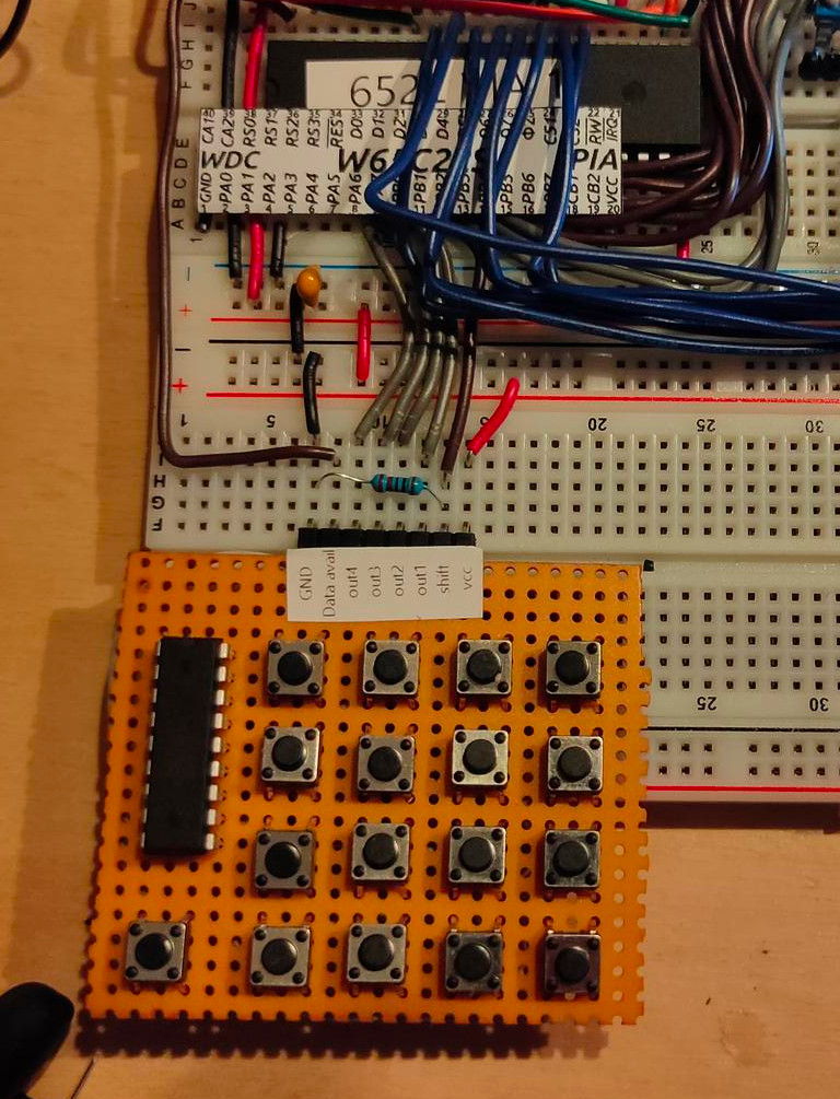
In this case designed for my 6502, but it is a generic setup.

I it just a dual 16key matrix decoder merged together. You can probably use this with raspberries, arduinos etc.

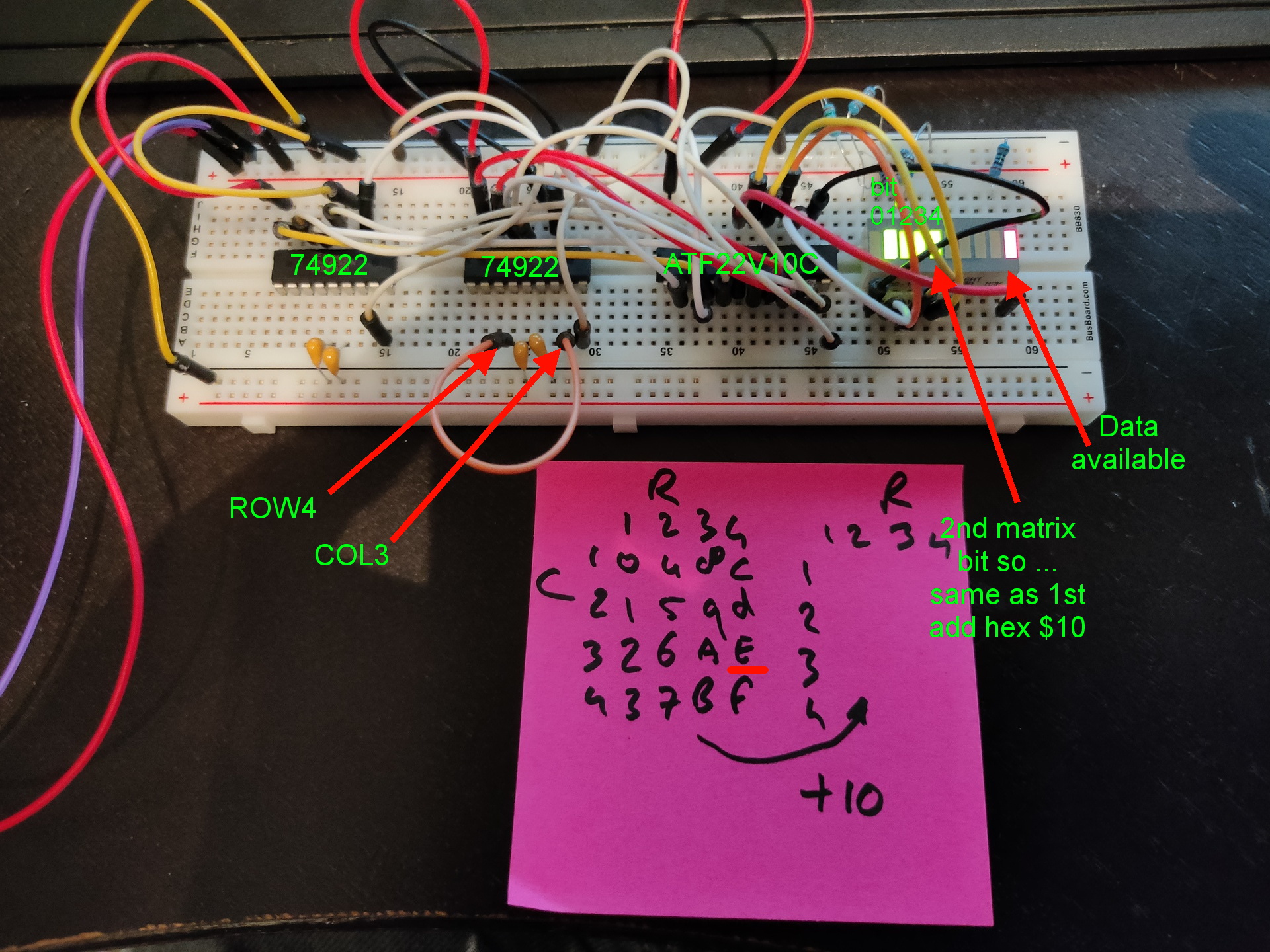
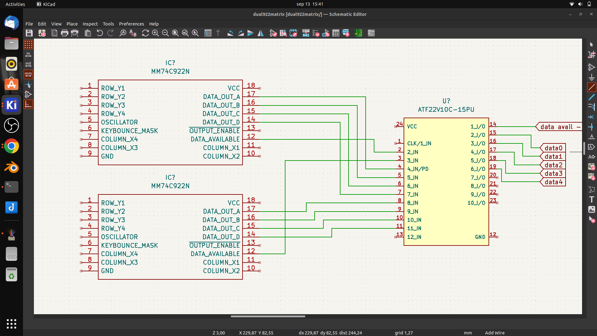
I wanted to use 74C923 but these are nowhere to be found. And even then, the number of keys wil be 20.
So i am tying together two 74C922 using some logic in a PLD.

First draft

It wil be something like above. Using the data availabe signal i can combine both 16key matrixes. (In theory .. it is all untested)

PLD Code

GAL22V10
Address Decoder

PHI2 DA0 DA1 D01 D02 D03 D04 D11 D12 D13 D14 GND
NC D0 D1 D2 D3 D4 DA NC NC NC NC VCC

DA = DA0 + DA1
D0 = D01 & DA0 + D11 & DA1
D1 = D02 & DA0 + D12 & DA1
D2 = D03 & DA0 + D13 & DA1
D3 = D04 & DA0 + D14 & DA1
D4 = DA1 

DESCRIPTION
Key matrix merger

I’ve got my new keys of the keyboard in today!

  • 0-F – hex keys
  • G = Go
  • R = Reset
  • S = Step
  • M = Memory
  • Cursor keys (up/down for memory locations)
  • ??? I’ve got room for 8 more keys

My inkscape template (keys are 10/10mm)

Printed on white and red paper

https://media.henriaanstoot.nl/keyboardmatrix.svg

6502 Update

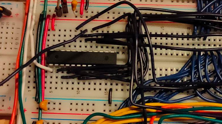
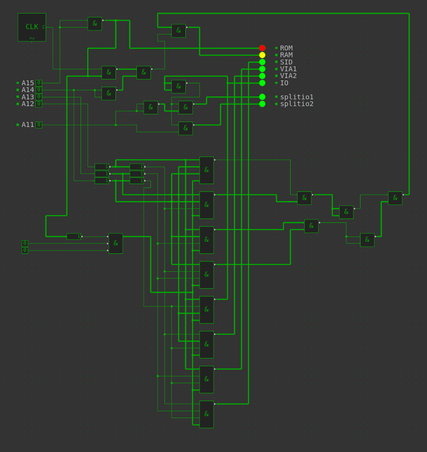
New address decoder in place!
Connected RAM/ROM/SID/VIA1/VIA2 and ACIA

ROM8000-FFFF
SID7000-700F (sound)
VIA16000-60xx (Hex key matrix)
ACIA6800-68xx (serial)
VIA2
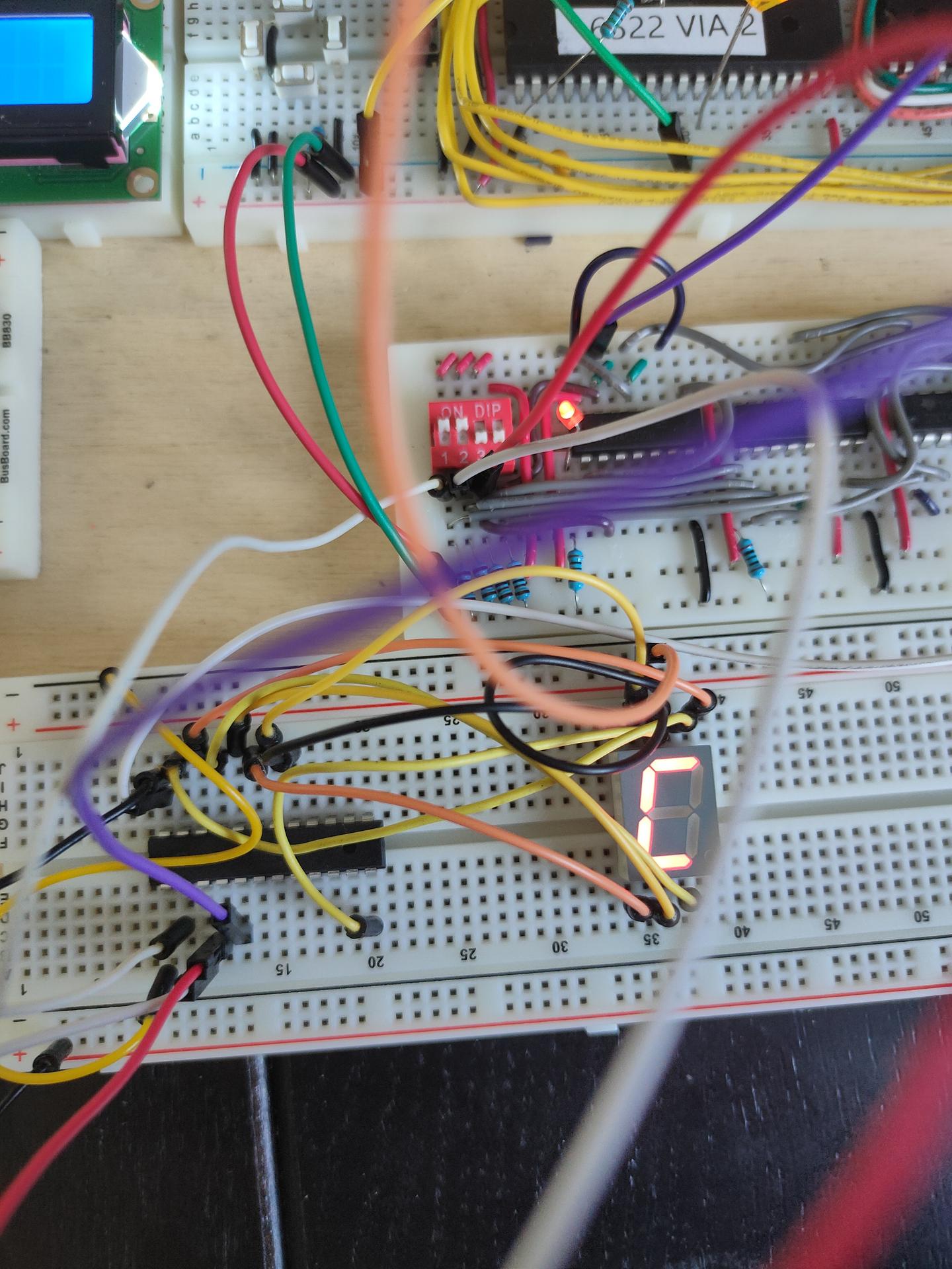
5000-50xx (led test at the moment)
RAM0000-3FFF

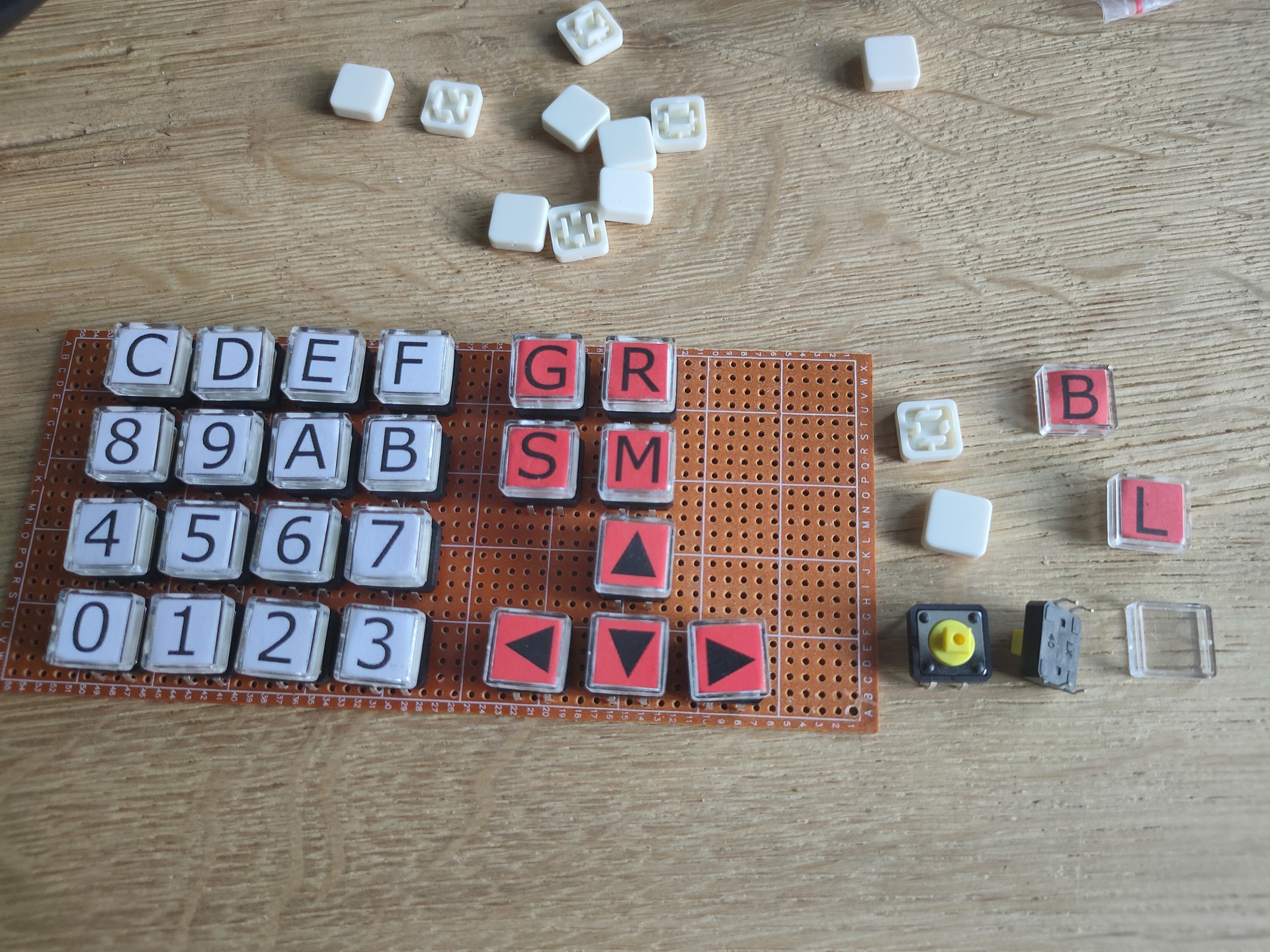
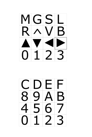
To plan: Bigger maxtrix keyboard and other displays
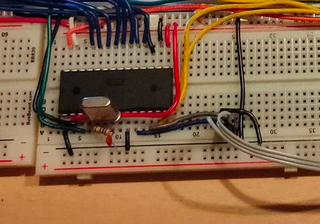
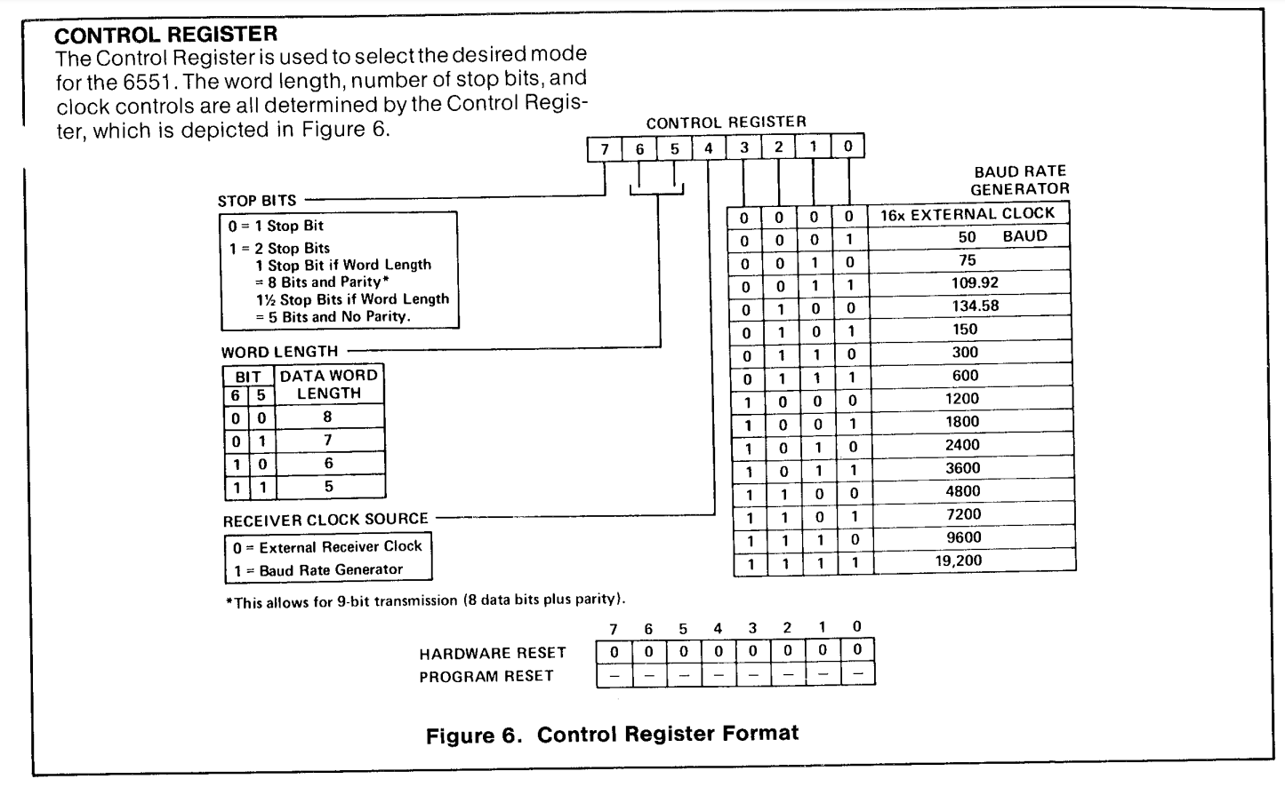
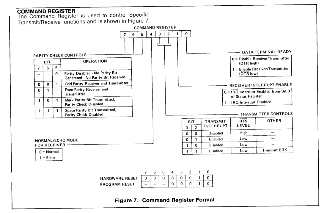
ACIA 6551

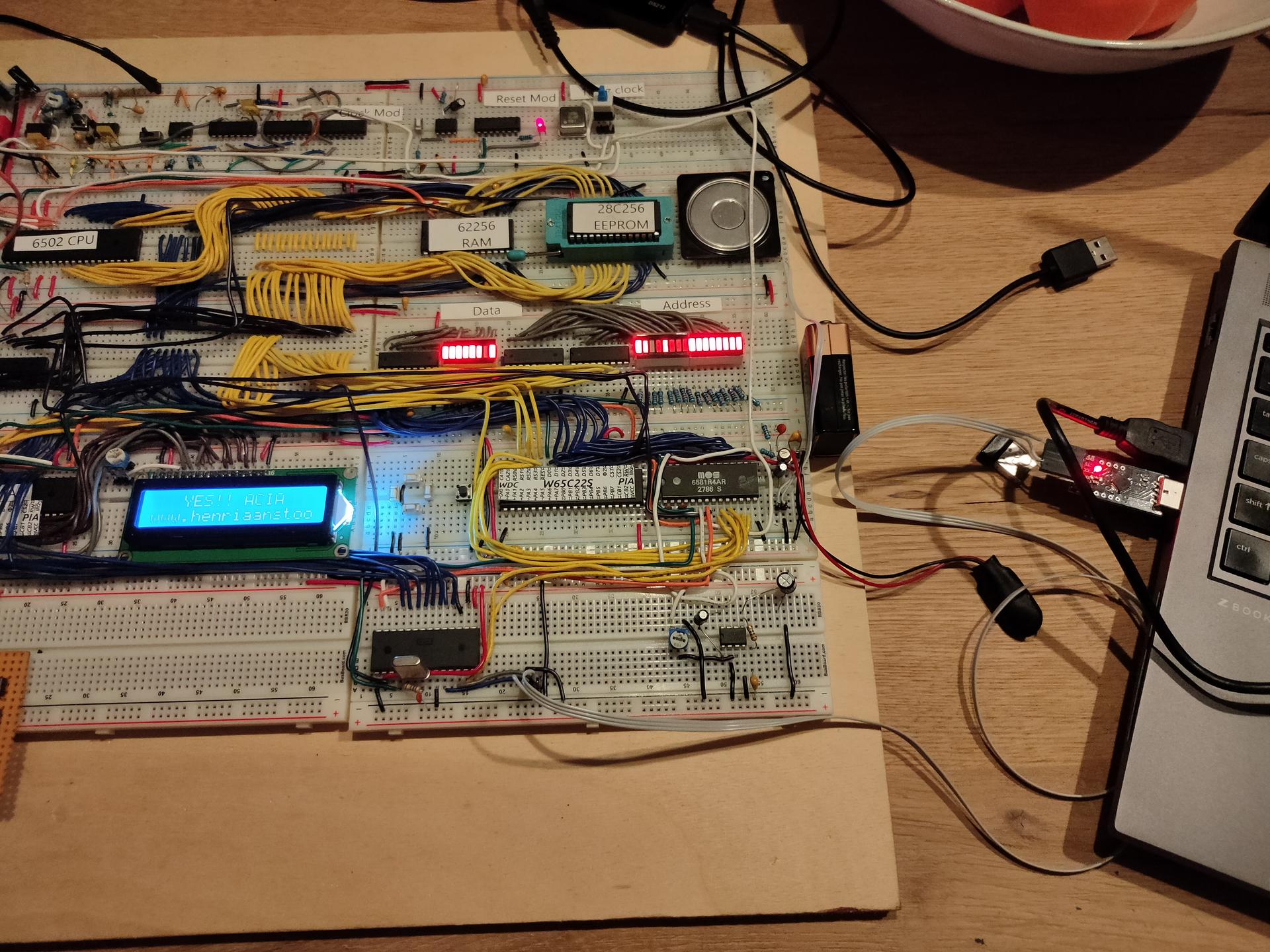
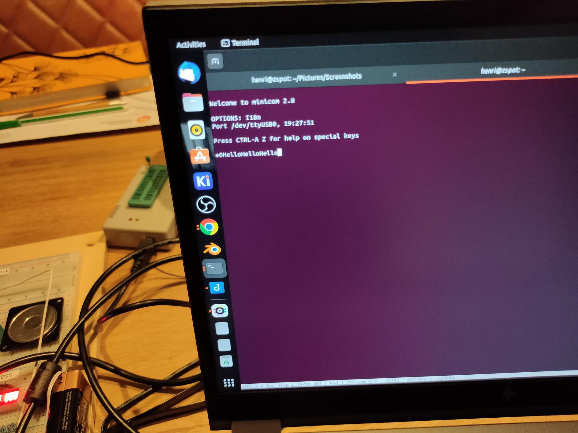
Got a serial connection working between the 6502 and my linux machine!

At the moment when a reset occurs , hello is being printed.
Text typed in the minicom terminal, is echo-ed back and displayed on the LCD display.

Things learned: Do not trust internet schematics blindly!

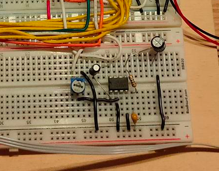
The crystal used for the ACIA (pin 6/7 1.8432Mhz needs a 1M ohm resistor parallel over the crystal, and a 30nF capacitor from pin 7 to GND

When using a terminal emulator, and using 3 wires. Disable hardware handshake.

Keyboard rewired.

What didnĀ“t work as planned:

New amplifier schematic for the SID. There is too much noise.

Amplifier with a LM628

Bought a dual power supply (5V and 12V). But this one has a lot of signal noise on the SID part and even my battlestation speakers!

LED test 2nd via

PORTB = $5000 ; VIA PORTB
PORTA = $5001 ; VIA PORTA
DDRB = $5002  ; Data direction register
DDRA = $5003  ; Data direction register

LED  = %10000000

	.org $8000

reset:

	lda #%11100000 ; Set top 3 pins on port A to output
	sta DDRA

	lda LED 
	sta PORTA

loop:		; done loop until doomsday
	jmp loop

irq:
nmi:
	.org $fffa
	.word nmi
	.word reset
	.word irq

ACIA part

ACIA_RX = $6800
ACIA_TX = $6800
ACIA_STATUS = $6801
ACIA_COMMAND = $6802
ACIA_CONTROL = $6803
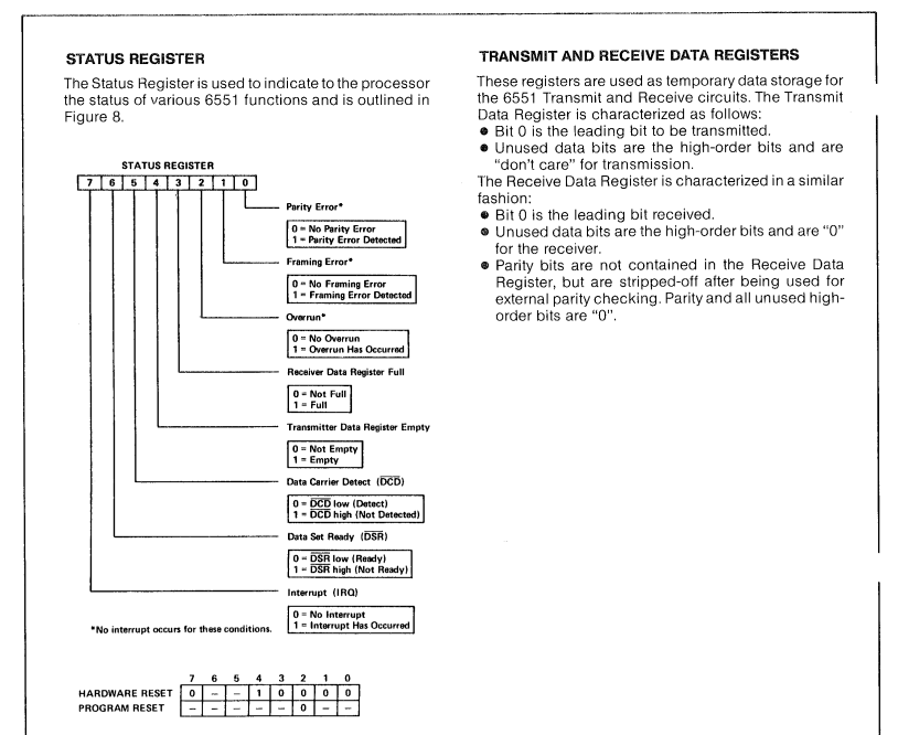
    lda #$00
    sta ACIA_STATUS
    lda #$0b
    sta ACIA_COMMAND
    lda #$1f
    sta ACIA_CONTROL

Address decoder in a ATF22V10

Whereas i needed to use several logical components to make a address decoder, below i only need one!

cat addressdecoder-fash.PLD 

ATF22V10 (GAL22V10)
Address Decoder

PHI2 A15 A14 A13 A12 A11 A10 A9  A8  A7  A6 GND
xx xx RAM ROM SID ACIA VIA1 VIA2 DEV0 DEV1 BANK VCC

/RAM = PHI2 * /A15 * /A14
/ROM = A15 * BANK
/SID = /A15 * A14 * A13 * A12
/VIA1 = /A15 * A14 * A13 * /A12 * /A11
/ACIA = /A15 * A14 * A13 * /A12 * A11
/VIA2 = /A15 * A14 * /A13 * A12

/DEV0 = A15 * /BANK

DESCRIPTION
Address decoder

galasm addressdecoder-fash.PLD # Generates below file which i can flash into the PLD

cat addressdecoder-fash.jed

Used Program:   GALasm 2.1
GAL-Assembler:  GALasm 2.1
Device:         GAL22V10

*F0
*G0
*QF5892
*L0924 11111111111111111111111111111111111111111111
*L0968 11100111111111111111111111111111111111111111
*L1496 11111111111111111111111111111111111111111111
*L1540 11111011011110110111111111111111111111111111
*L2156 11111111111111111111111111111111111111111111
*L2200 11111011011101111011101111111111111111111111
*L2904 11111111111111111111111111111111111111111111
*L2948 11111011011101111011011111111111111111111111
*L3652 11111111111111111111111111111111111111111111
*L3696 11111011011101110111111111111111111111111111
*L4312 11111111111111111111111111111111111111111111
*L4356 11010111111111111111111111111111111111111111
*L4884 11111111111111111111111111111111111111111111
*L4928 01111011101111111111111111111111111111111111
*L5808 01000101010101010100
*L5828 0100000101100100011001000111001001100101011100110111001100100000
*C50fa
*
b734
Only the left chip! .. The two on the right are 7Segment decoders

So one chip replaces schematic below!

Programming ATF22V10 PLD – 7 Segment with Linux

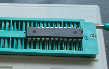
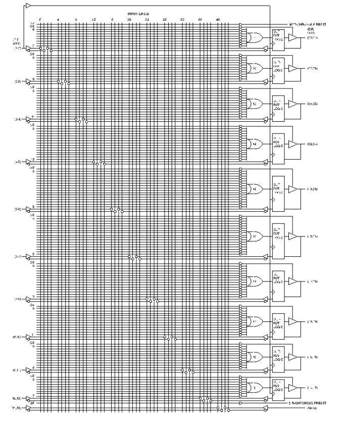
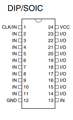
The ATF22V10 is a Programmable Logic Device. This means you can program the logic in the chip.

Internally it looks like a big matrix of connections which you can program to connect/disconnect from certain logic.

It has just a bunch of inputs/outputs

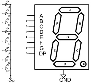
So if we want to have a 7 Segment decoder (you can easily buy a BCD decoder .. but these only work for displaying 0-9 and not 0-9A-F for displaying HEX numbers)

7 Segment display
Binary IN7 Segment decodedDisplays
D C B AA B C D E F G
0 0 0 01 1 1 1 1 1 00
0 0 0 10 1 1 0 0 0 0 1
0 0 1 0 1 1 0 1 1 0 12
0 0 1 11 1 1 1 0 0 13
0 1 0 00 1 1 0 0 1 14
0 1 0 11 0 1 1 0 1 15
0 1 1 0 1 0 1 1 1 1 16
0 1 1 1 1 1 1 0 0 0 0 7
1 0 0 01 1 1 1 1 1 18
1 0 0 11 1 1 1 0 1 19
1 0 1 01 1 1 0 1 1 1A
1 0 1 10 0 1 1 1 1 1B
1 1 0 0 1 0 0 1 1 1 0C
1 1 0 10 1 1 1 1 0 1D
1 1 1 01 0 0 1 1 1 1E
1 1 1 11 0 0 0 1 1 1F

Now we see that segment A is 1 in the case of (0,2,3,5,6,7,8,9,A,C,E,F)

When programming the PLD we can write that as: (note / means inverted a plus is OR, and * is AND)
So A is 0 in case of input being (1,4,B,D)

/QA = /D1 * /C1 * /B1 * A1
    + /D1 * C1 * /B1 * /A1
    + D1 * /C1 * B1 * A1
    + D1 * C1 * /B1 * A1

Complete code for galasm

Compiling and burning

GAL22V10
7SEGMENT

Clock   D1   C1   B1   A1    D2   C2    B2    A2    NC  NC   GND
/OE   NC    NC  NC  QG    QF    QE    QD   QC    QB   QA   VCC


/QA =   /D1 * /C1 * /B1 * A1
        + /D1 * C1 * /B1 * /A1
        + D1 * /C1 * B1 * A1
        + D1 * C1 * /B1 * A1

/QB=    /D1 * C1 * /B1 * A1
        + /D1 * C1 * B1 * /A1
        + D1 * /C1 * B1 * A1
        + D1 * C1 * /B1 * /A1
        + D1 * C1 * B1 * /A1
        + D1 * C1 * B1 * A1

/QC =   /D1 * /C1 * B1 * /A1
        + D1 * C1 * /B1 * /A1
        + D1 * C1 * B1 * /A1
        + D1 * C1 * B1 * A1


/QD=      /D1 * /C1* /B1 * A1
        + /D1 * C1 * /B1 * /A1
        + /D1 * C1 * B1 * A1
        + D1 * /C1 * B1 * /A1
        + D1 * C1 * B1 * A1

/QE =     /D1 * /C1 * /B1 * A1
        + /D1 * /C1 * B1 * A1
        + /D1 * C1 * /B1 * /A1
        + /D1 * C1 * /B1 * A1
        + /D1 * C1 * B1 * A1
        + D1 * /C1 * /B1 * A1

/QF =     /D1 * /C1 * /B1 * A1
        + /D1 * /C1 * B1 * /A1
        + /D1 * /C1 * B1 * A1
        + /D1 * C1 * B1 * A1
        + D1 * C1 * /B1 * A1

/QG =     /D1 * /C1 * /B1 * /A1
        + /D1 * /C1 * /B1 * A1
        + /D1 * C1 * B1 * A1
        + D1 * C1 * /B1 * /A1

DESCRIPTION
A 7 segment hex decoder

galasm 7seghex.gal

minipro -p ATF22V10CQZ -w 7seghex.jed

minipro -p ATF22V10CQZ -w 7seghex.jed
Found TL866II+ 04.2.129 (0x281)
Warning: Firmware is newer than expected.
  Expected  04.2.128 (0x280)
  Found     04.2.129 (0x281)

VPP=12V
Warning! JED file doesn't match the selected device!

Declared fuse checksum: 0x98D5 Calculated: 0x98D5 ... OK
Declared file checksum: 0x40B3 Calculated: 0x41A8 ... Mismatch!
JED file parsed OK

Use -P to skip write protect

Erasing... 0.33Sec OK
Writing jedec file...  5.01Sec  OK
Reading device...  0.32Sec  OK
Writing lock bit... 0.35Sec OK
Verification failed at address 0x16C6: File=0x01, Device=0x00 < ------------------ Gives error, but burning seems okay

henri@zspot:~/projects/galasm$ minipro -p ATF22V10CQZ -r 7seghex.out
Found TL866II+ 04.2.129 (0x281)
Warning: Firmware is newer than expected.
  Expected  04.2.128 (0x280)
  Found     04.2.129 (0x281)
Reading device...  0.32Sec  OK

Gives all zeros as output, but device works!