This weekend I saw a corridor crew video about controlling CGI objects using input devices.
This made me think of a half finished project I did a while ago.
So lets finish it.
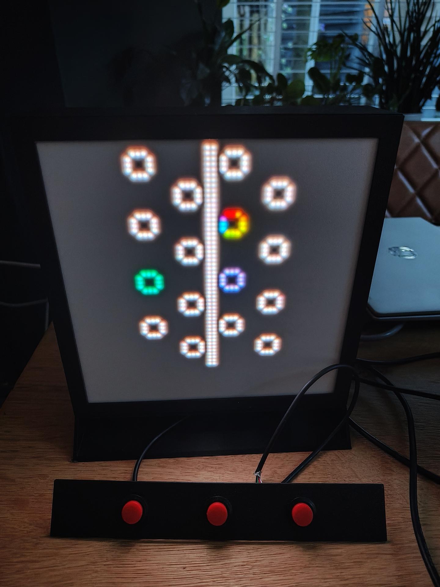
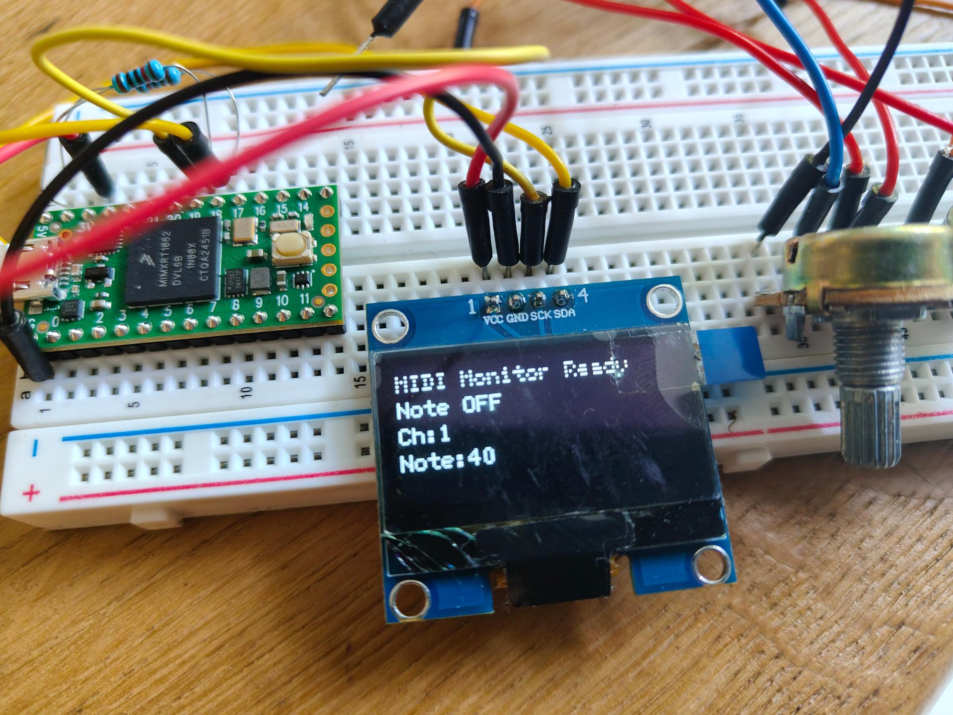
(I know, dirty screen .. too much outside hacking)
CODE for wemos
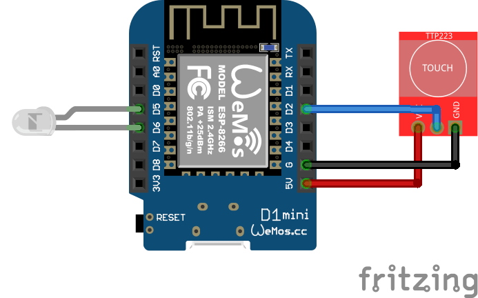
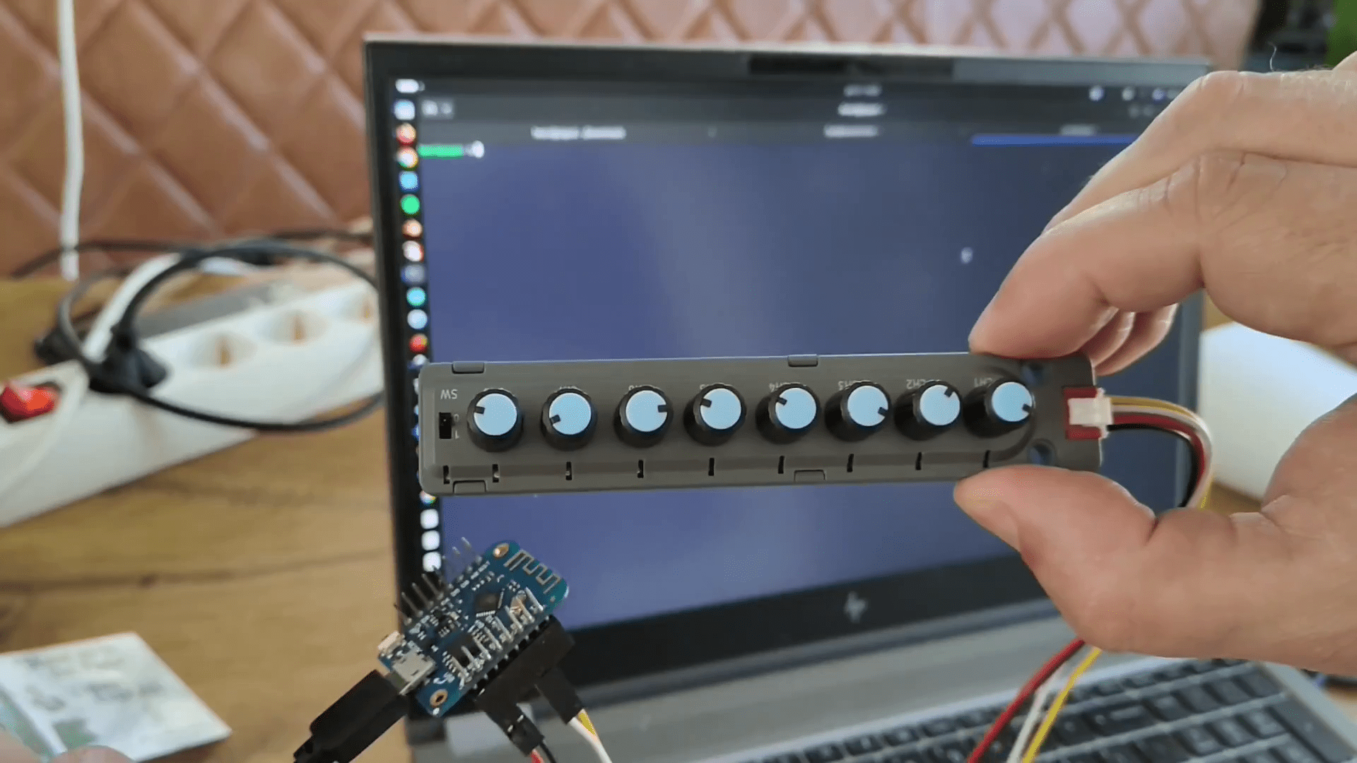
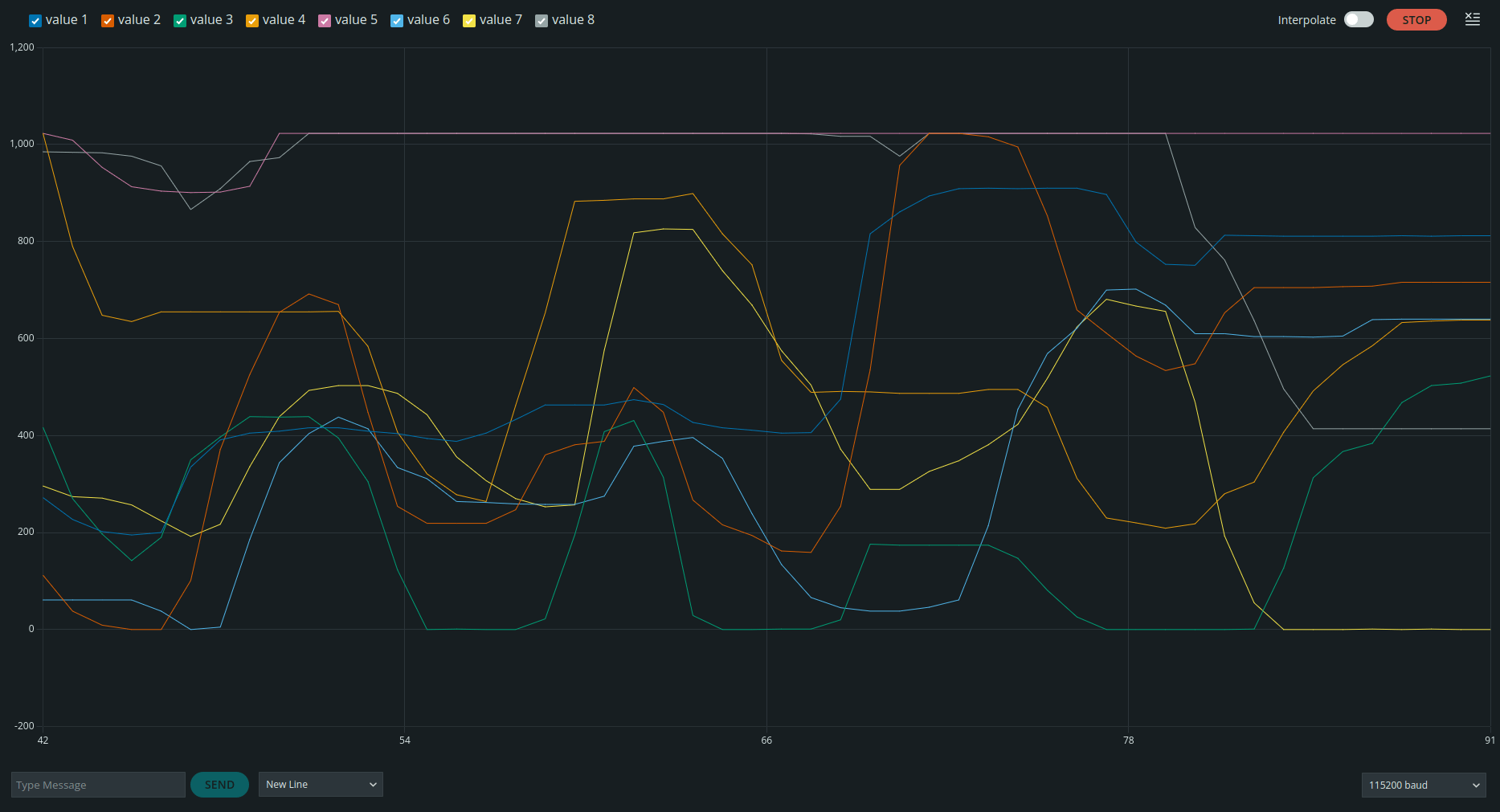
Very simple code to read pots using I2C and printing values on the serial output using the wemos.
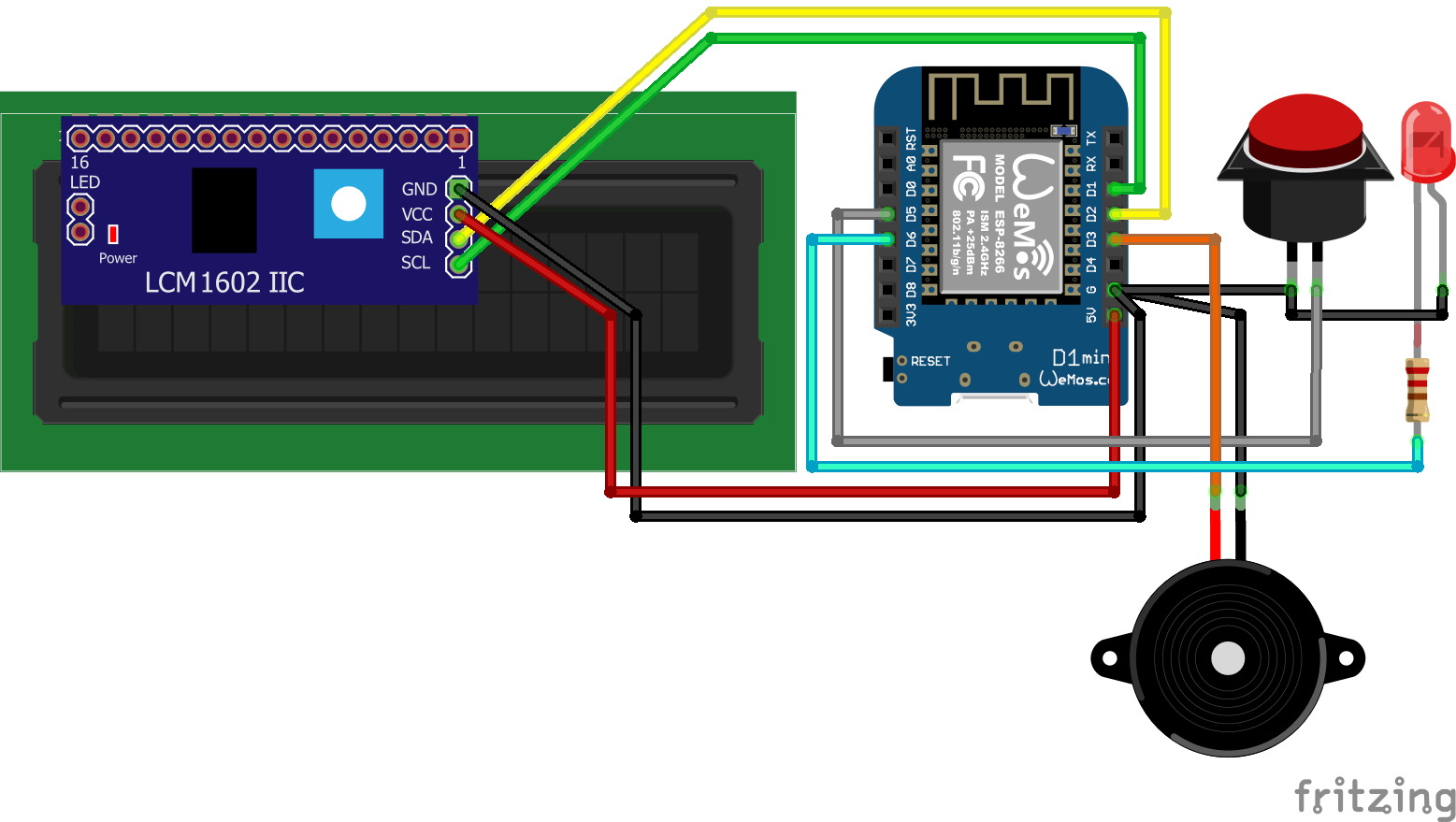
Only needs 5V,GND,SDA,SCL (D1 D2)
279,206,520,1023,1023,60,300,985,0
Output example 8 potmeters 0-1023 value and last value 0 or 1 for the switch
Serial plotter example below
#include "m5angle8.h"

M5ANGLE8 MM;

void setup()
{
  Serial.begin(115200);

  Serial.println();
  delay(100);

  Wire.begin();
  MM.begin();
}


void loop()
{
  for (int ch = 0; ch < 8; ch++)
  {
    Serial.print(MM.analogRead(ch, 10));
    Serial.print(",");
    delay(1);
  }
  Serial.print(MM.inputSwitch());
  Serial.print("\n");
  delay(100);
}
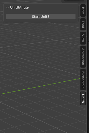
Plugin for Blender
filename unit8angle_blender/__init__.py
made into a zip you can install using
zip -r myplugin.zip unit8angle_blender
Blender edit > preferences > add-ons > Install from disk
import bpy
import serial
import serial.tools.list_ports

ser = None


def open_serial():
    global ser

    if ser:
        return

    # Change this to your COM port
    ser = serial.Serial("/dev/ttyUSB0",115200,timeout=0)


class SERIAL_OT_start(bpy.types.Operator):
    bl_idname = "wm.unit8_start"
    bl_label = "Start Unit8"

    _timer = None

    def modal(self, context, event):

        if event.type == 'TIMER':

            global ser

            if ser and ser.in_waiting:

                line = ser.readline().decode(errors="ignore").strip()

                try:

                    values = list(map(int,line.split(",")))

                    if len(values) >= 8:

                        obj = context.active_object

                        if obj:

                            obj.location.x = values[0] / 100.0
                            obj.location.y = values[1] / 100.0
                            obj.location.z = values[2] / 100.0

#                            obj.location.x = values[0] / 1023.0
#                            obj.location.y = values[1] / 1023.0
#                            obj.location.z = values[2] / 1023.0

                            obj.rotation_euler.x = values[3] / 1023.0 * 6.28318
                            obj.rotation_euler.y = values[4] / 1023.0 * 6.28318
                            obj.rotation_euler.z = values[5] / 1023.0 * 6.28318

                            s = 0.1 + values[6] / 1023.0 * 3.0
                            obj.scale = (s,s,s)

                except Exception:
                    pass

        return {'PASS_THROUGH'}

    def execute(self, context):

        open_serial()

        wm = context.window_manager

        self._timer = wm.event_timer_add(0.01, window=context.window)

        wm.modal_handler_add(self)

        return {'RUNNING_MODAL'}


class SERIAL_PT_panel(bpy.types.Panel):
    bl_label = "Unit8Angle"
    bl_space_type = 'VIEW_3D'
    bl_region_type = 'UI'
    bl_category = 'Unit8'

    def draw(self, context):
        self.layout.operator("wm.unit8_start")


classes = (
    SERIAL_OT_start,
    SERIAL_PT_panel,
)


def register():
    for c in classes:
        bpy.utils.register_class(c)


def unregister():
    for c in reversed(classes):
        bpy.utils.unregister_class(c)