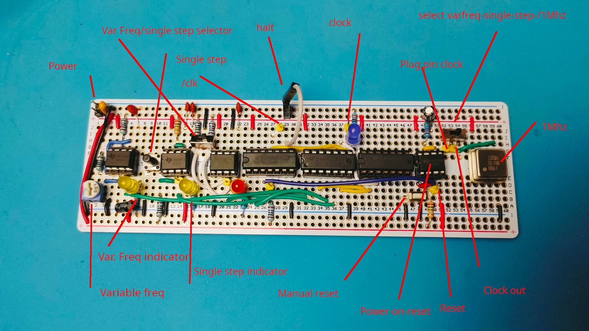
My previous build of the clock module is as Ben designed. Wellll . Not really, I added some components to change the clock range.
Okay, Ben’s design is awesome. Not because of its technical design. No, you will learn to use the NE555 chip in three ways!
Variable freq, debounce with delay and a flip-flop like switch
I added another function to it. While making my version.
I added a 555 power-on reset pulse part.
I used a perm board (which is shorter than a regular breadboard)
And I moved some components over and added some LEDs/pin headers.
While doing so, I only used 3/4 of the board.
So I added a power-on reset part with a manual push-button. (Partly like the C64 power-on)
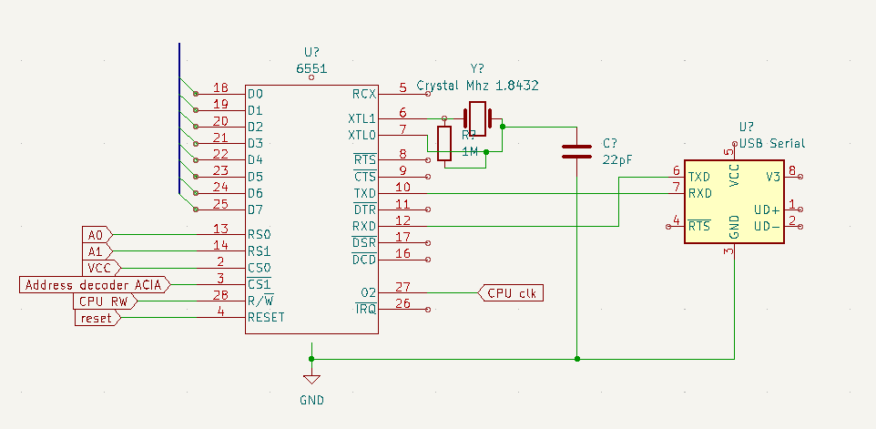
I also added the 1Mhz crystal.
Rest of the boards will use JST connectors for the bus-connections.
I am working on big motor controllers and 3D print modelling for clients.