Last Updated or created 2025-06-29
Below some examples and connection diagrams to control displays.
More code and complete schematics will be added on this page or on a separate projects page.
UPDATE 20230119 Cost of 20×4 display in 1998
LCD
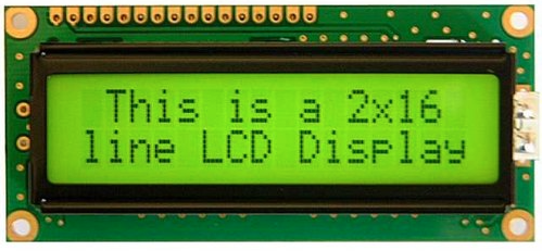
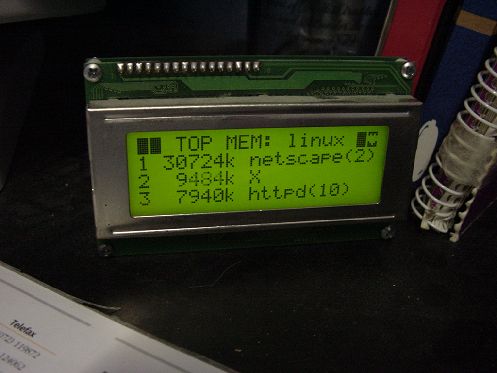
I’ve used a LCD display like this (HITACHI HD44780) on my PC in the 90s, and also written code to use this as a monitoring device on my amiga.
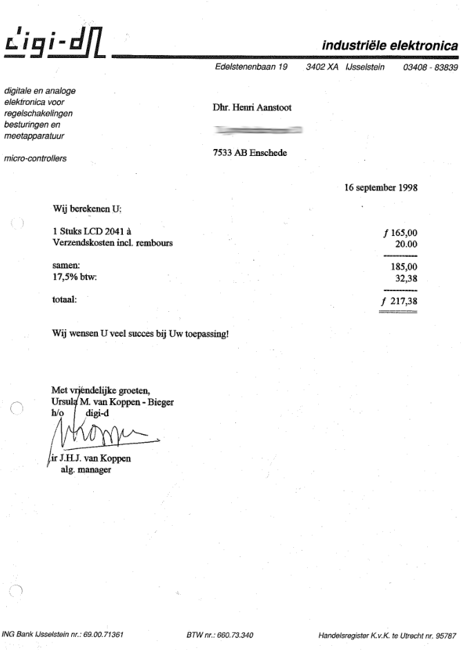
When bought now fl to euro 98 Euro or 107 $
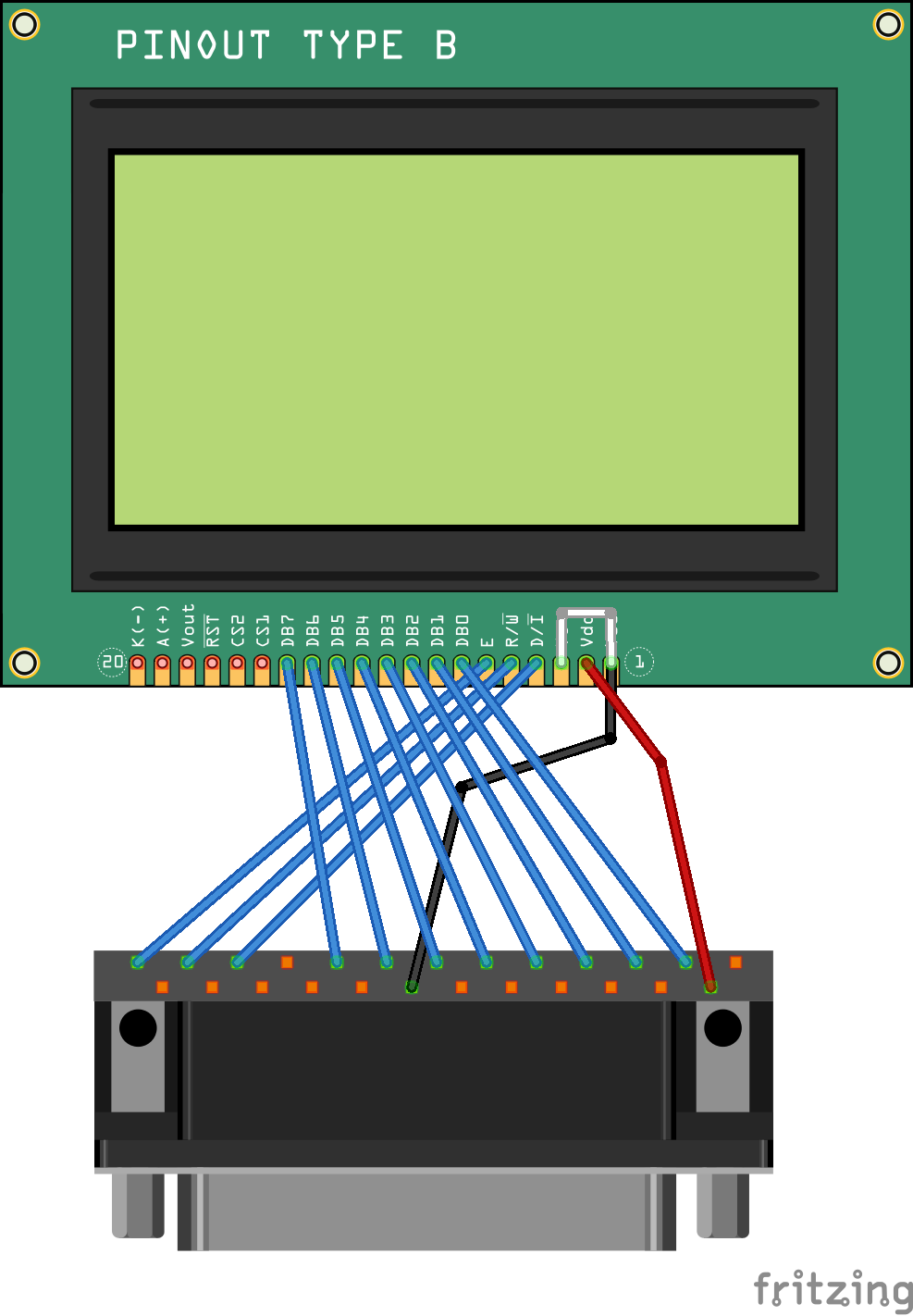
;LCD Display Module             Parallel port
;        1 Vss                  20 GND
;        2 Vdd                  14 +5V
;        3 Vlc                  20 GND (contrast LCD display)
;        4 RS (register select) 11 BUSY
;        5 R/W                  12 POUT
;        6 E (enable)           13 SEL
;        7 DB0                   2 D0
;        8 DB1                   3 D1
;        9 DB2                   4 D2
;       10 DB3                   5 D3
;       11 DB4                   6 D4
;       12 DB5                   7 D5
;       13 DB6                   8 D6
;       14 DB7                   9 D7
Amiga code part
        bsr     initprt         ; CIA 8520 init
        bsr     initlcd         ; init lcd display module
        move.l  #0,d0
        rts

initprt:move.b  #$ff,$bfe301    ; parallel port is output
        move.b  $bfd200,d0
        ori.b   #$07,d0         ; select, p-out and busy
        move.b  d0,$bfd200
        rts

initlcd:move.w  #$38,d0         ; multiple reset
        bsr     send
        bsr     delay2
        move.w  #$38,d0
        bsr     send
        bsr     delay2
        move.w  #$38,d0         ; 2*8 lines
        bsr     send
        bsr     delay2
        move.w  #$01,d0         ; clear display
        bsr     send
        bsr     delay2          ; wait
        move.w  #$0c,d0         ; display on
        bsr     send
        move.w  #$06,d0         ; Entry Mode Set
        bsr     send
        rts

send:   bsr     delay
        btst    #8,d0           ; test rs bit
        beq     reg0
        bsr     rs1             ; select register 1
        bra     skip
reg0:   bsr     rs0             ; select register 0
skip:
        bsr     delay
        bsr     rw0             ; read/write=0
        bsr     delay
        bsr     e1              ; enable = 1
        bsr     delay
        move.b  d0,$bfe101      ; push data
        bsr     delay
        bsr     e0
        bsr     delay
        rts

delay:  move.w  #$20,d1
dloop:  subi    #1,d1
        bne     dloop
        rts

delay2: move.w  #$800,d1
dloop2: subi    #1,d1
        bne     dloop2
        rts
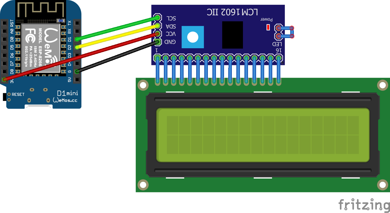
#include <ESP8266WiFi.h>
#include <PubSubClient.h>
#include <Wire.h>
#include <LiquidCrystal_I2C.h>
LiquidCrystal_I2C lcd(0x27, 20, 4);
const char* ssid = "MYACCESSPOINT";
const char* password = "MYPASSWORD";
const char* mqtt_server = "mymqttserver";
const byte ledRed = 12;
const byte horn = 13;
int button = 2;
int press = 0;
boolean buttonToggle = true;


// Todo : DISPLAY 2ND LINE, DISPLAY SILENT, ...

WiFiClient espClient;
PubSubClient client(espClient);
bool toggle = false;
void setup_wifi() {
  delay(100);

  Serial.print("Connecting to ");
  Serial.println(ssid);
  WiFi.begin(ssid, password);
  while (WiFi.status() != WL_CONNECTED)
  {
    delay(500);
    Serial.print(".");
  }
  randomSeed(micros());
  Serial.println("");
  Serial.println("WiFi connected");
  Serial.println("IP address: ");
  Serial.println(WiFi.localIP());
}

void callback(char* topic, byte* payload, unsigned int length)
{
  if (length > 0) {
    toggle = true;
  }

  if (length == 0) {
    toggle = false;
  }

  Serial.print("Command from MQTT broker is : [");
  Serial.print(topic);

  Serial.println();
  Serial.print(" publish data is:");
  lcd.clear();
  lcd.backlight(); // turn off backlight

  {

    for (int i = 0; i < length; i++)
    {
      Serial.print((char)payload[i]);
      if (i < 16){
      lcd.setCursor(0, 0);
      lcd.setCursor(i, 0);
      } else {
      lcd.setCursor(0, 1);
      lcd.setCursor(i-16, 1);
      }
      lcd.write((char)payload[i]);
    }
  }


  Serial.println();
}

void reconnect() {

  while (!client.connected())
  {
    Serial.print("Attempting MQTT connection...");

    String clientId = "mqttlcd";
    clientId += String(random(0xffff), HEX);

    if (client.connect(clientId.c_str()))
    {
      Serial.println("connected");

      client.subscribe("mqttlcd/message");
    } else {
      Serial.print("failed, rc=");
      Serial.print(client.state());
      Serial.println(" try again in 5 seconds");
      delay(6000);
    }
  }
}

void setup() {
  Serial.begin(115200);
  pinMode(button, INPUT);
  digitalWrite(2, HIGH);
  pinMode(ledRed, OUTPUT);
  digitalWrite(ledRed, LOW);
  pinMode(horn, OUTPUT);
  digitalWrite(horn, LOW);
  setup_wifi();
  client.setServer(mqtt_server, 1883);
  lcd.init();
  lcd.backlight();
}

void loop() {


  if (!client.connected()) {
    reconnect();
  }
  if (toggle == true) {
    digitalWrite(ledRed, HIGH);
    digitalWrite(horn, HIGH);
    delay(200);
    digitalWrite(ledRed, LOW);
    digitalWrite(horn, LOW);
    delay(200);
  }
  if (toggle == false) {
    digitalWrite(ledRed, LOW);
    digitalWrite(horn, LOW);

  }

  client.setCallback(callback);
  client.loop();

  press = digitalRead(button);
  if (press == LOW)
  {
    if (buttonToggle)
    {
      digitalWrite(ledRed, HIGH);
      digitalWrite(horn, HIGH);
      buttonToggle = !buttonToggle;
    }
    else
    {
      digitalWrite(ledRed, LOW);
      digitalWrite(horn, LOW);
      buttonToggle = !buttonToggle;
      toggle = false;
      client.publish("mqttlcd/button","pressed");
      lcd.clear();
      lcd.noBacklight(); // turn off backlight
    }
  }
  delay(500);  //delay for debounce
}
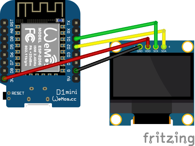
Oled
There are several oled displays, mostly controllable with i2c but some of them are SPI
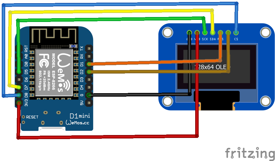
SSD1306 – I2c connected
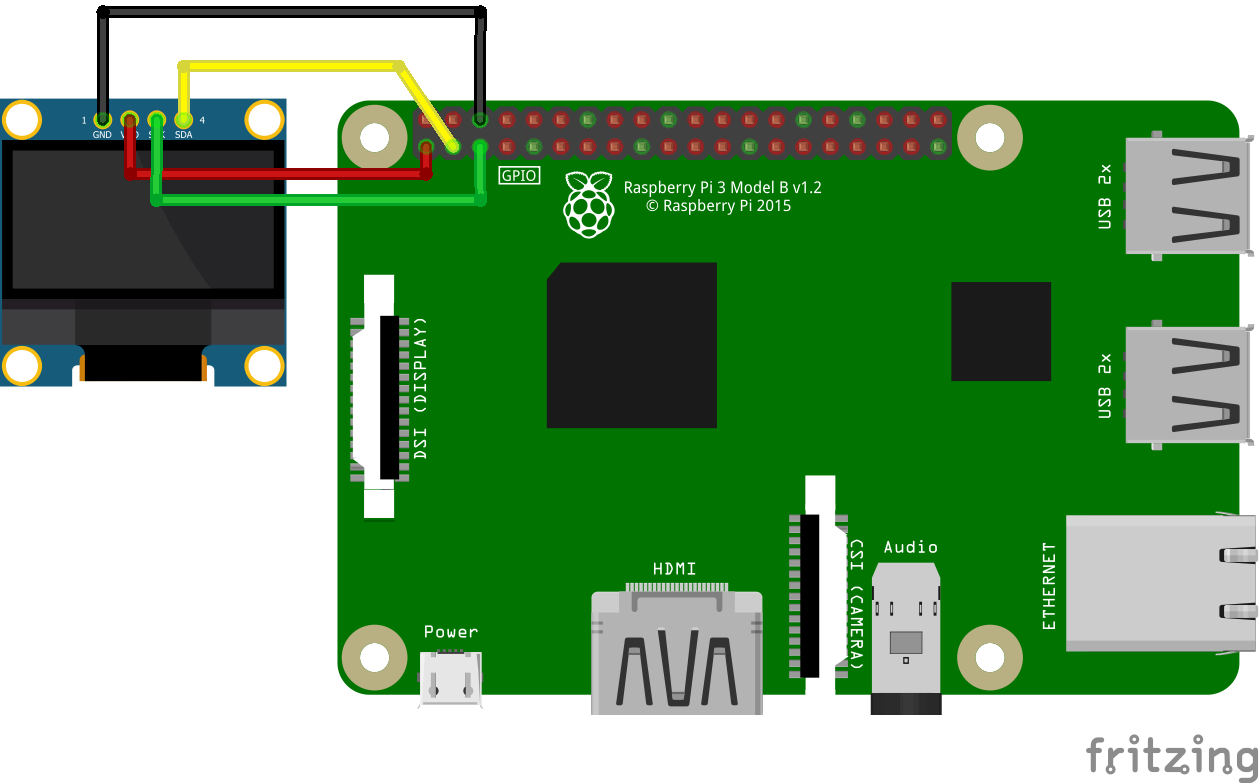
pip3 install adafruit-circuitpython-ssd1306
git clone https://github.com/adafruit/Adafruit_Python_SSD1306 (old)
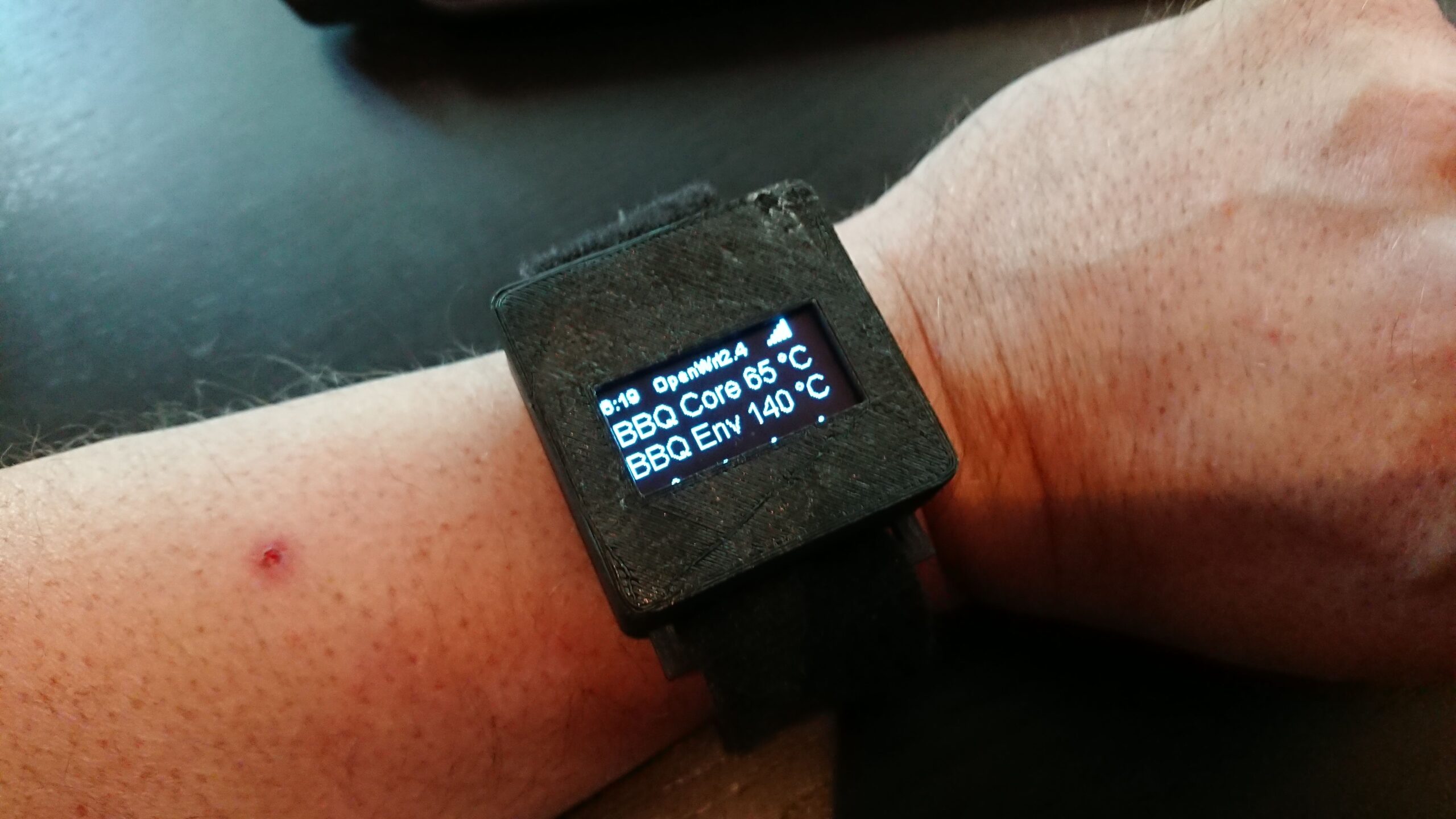
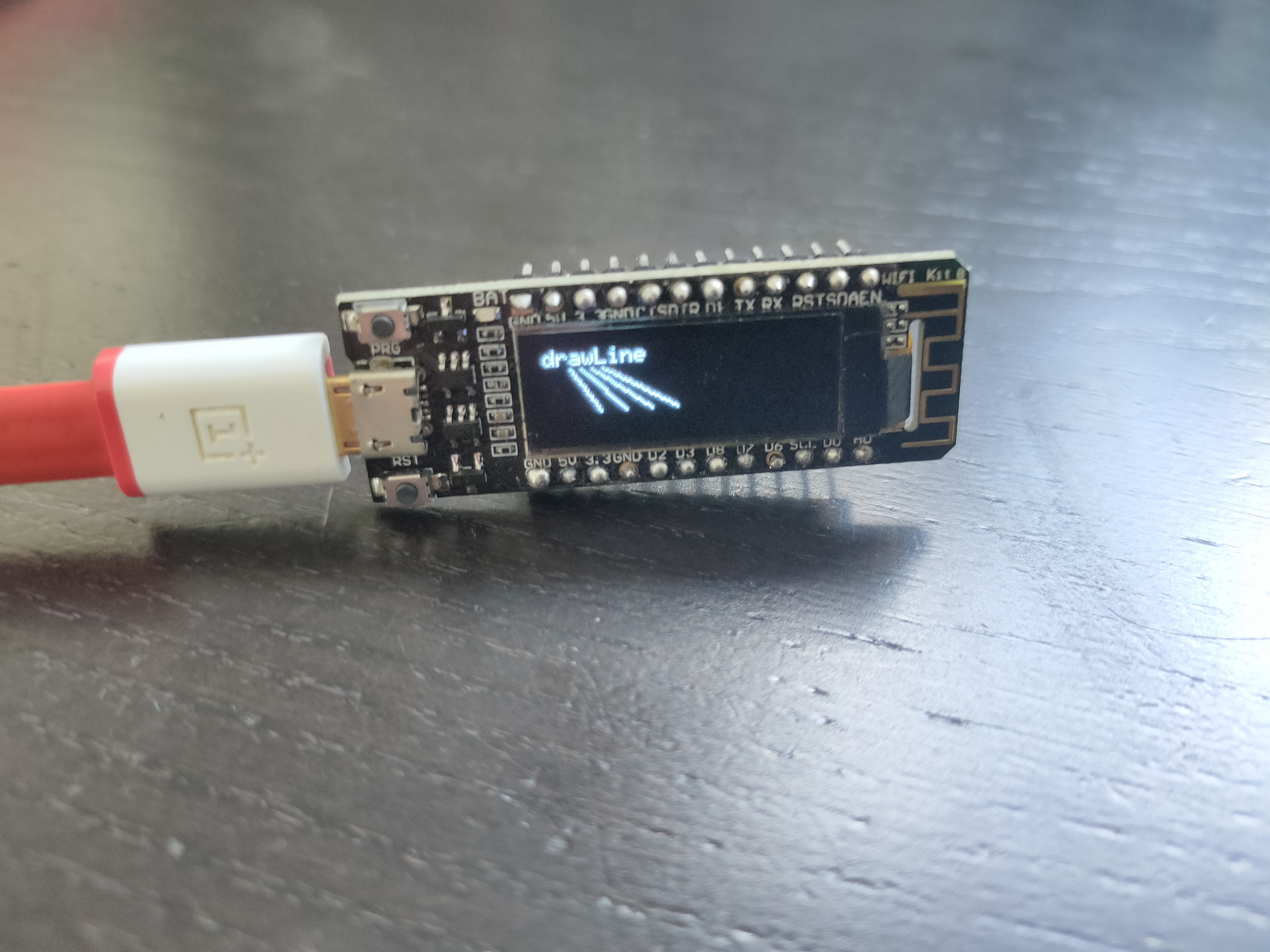
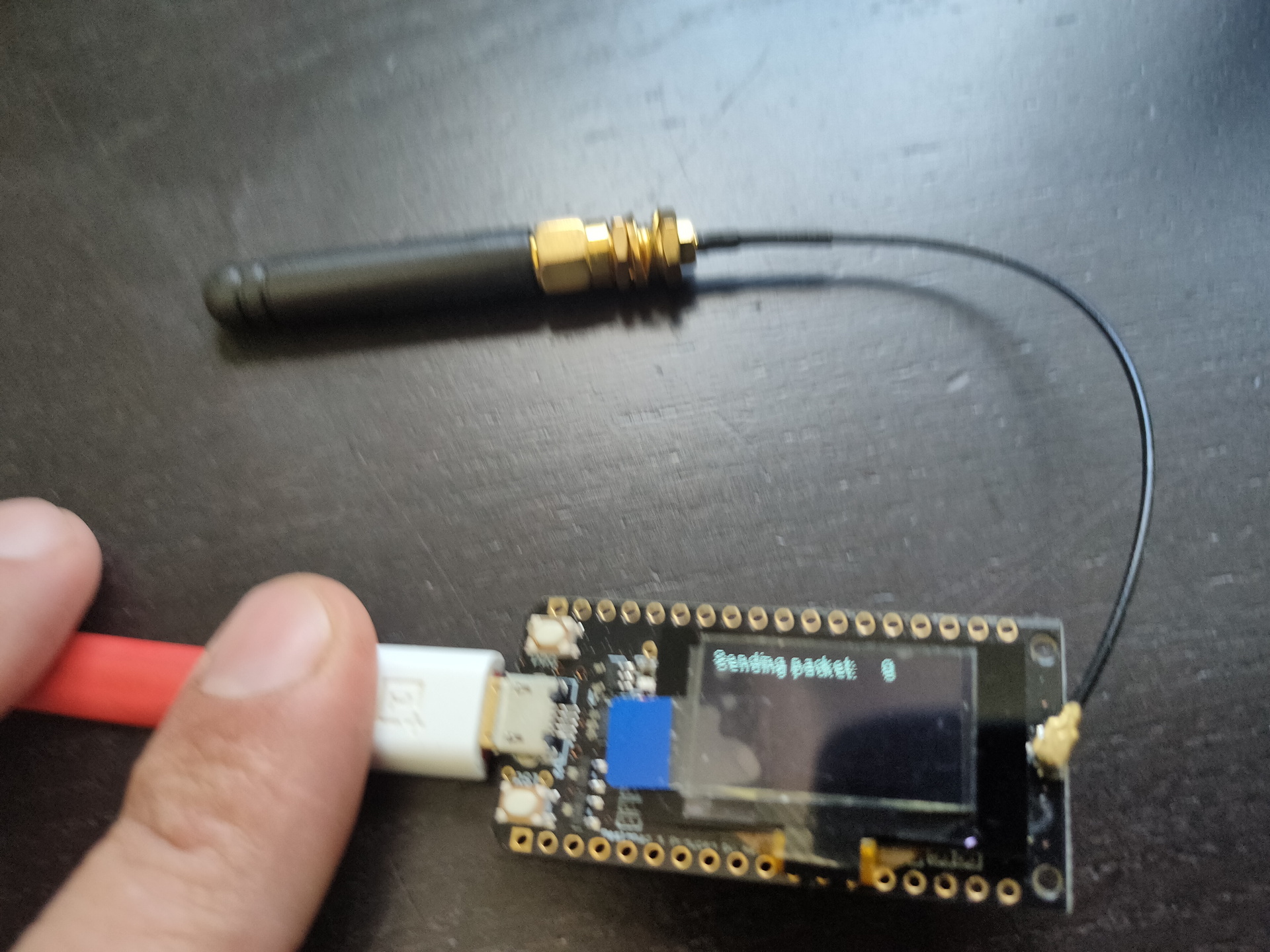
Edit file - comment SPI sectionSome arduino’s have embedded displays like those i’ve used for a Lora project.
Other means of connecting : SPI
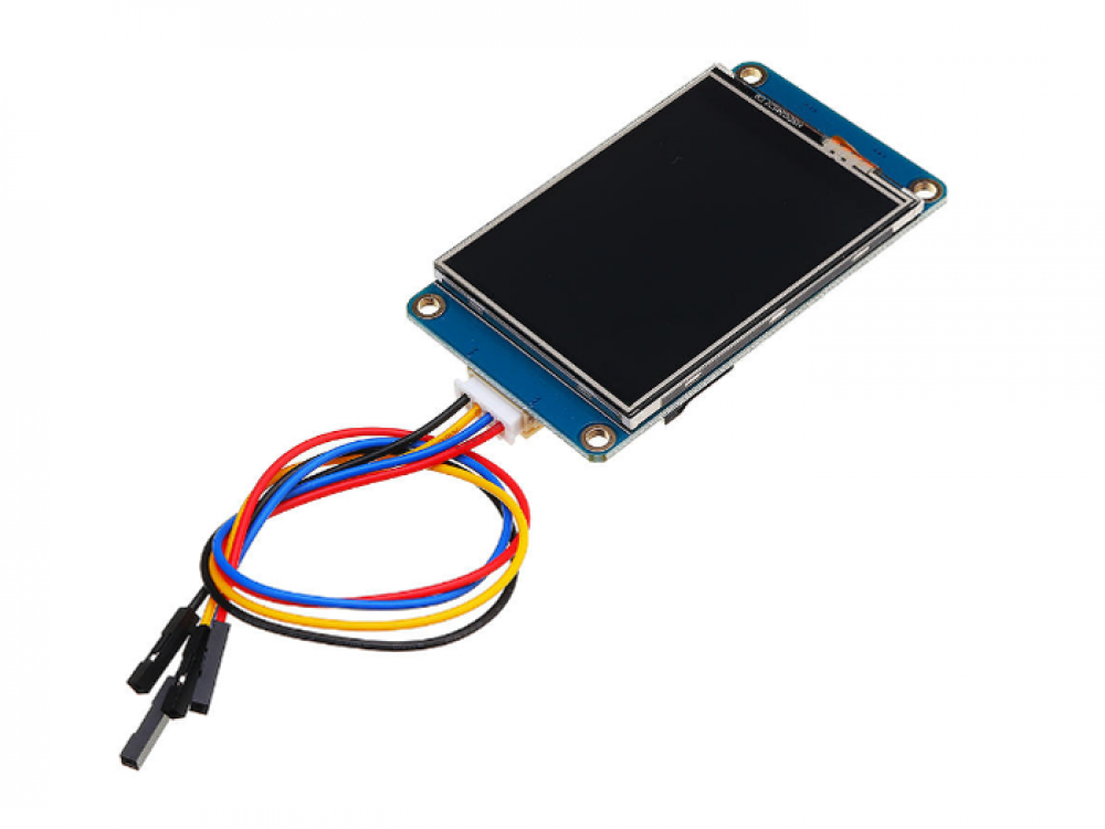
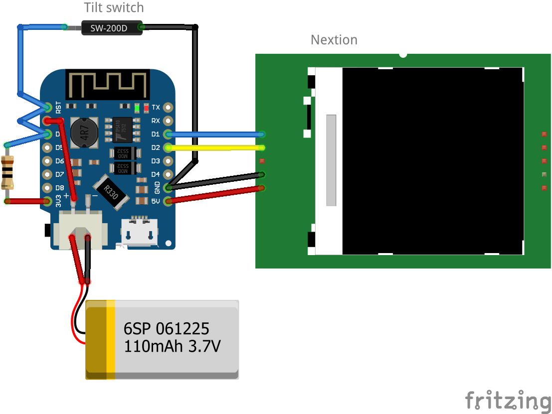
Nextion
Nextion is a Human Machine Interface (HMI) solution combining an onboard processor and memory touch display with Nextion Editor software for HMI GUI project development.
Using the Nextion Editor software, you can quickly develop the HMI GUI by drag-and-drop components (graphics, text, button, slider, etc.) and ASCII text-based instructions for coding how components interact on the display side.
Nextion HMI display connects to peripheral MCU via TTL Serial (5V, TX, RX, GND) to provide event notifications that peripheral MCU can act on, the peripheral MCU can easily update progress, and status back to Nextion display utilizing simple ASCII text-based instructions.
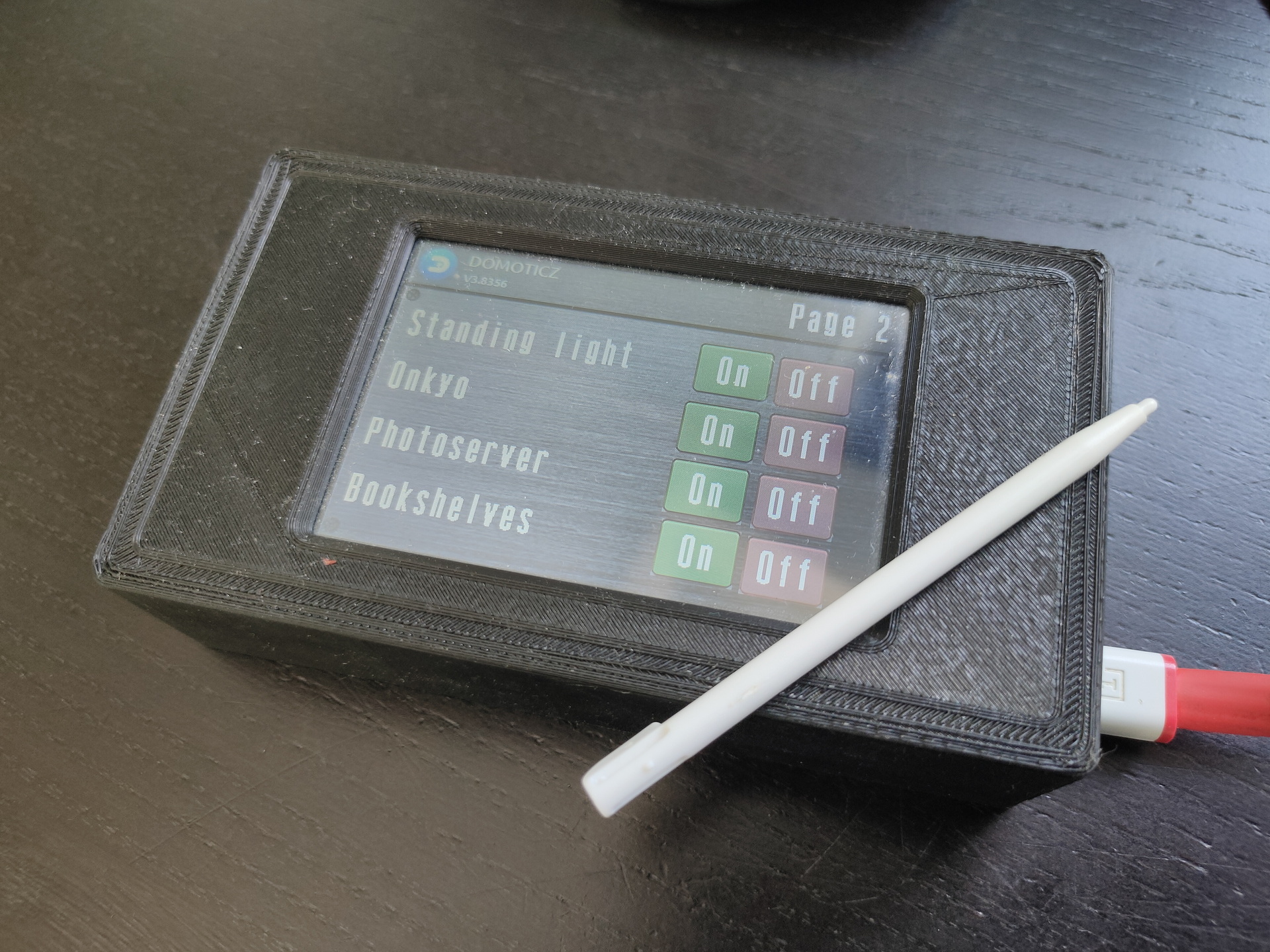
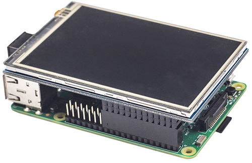
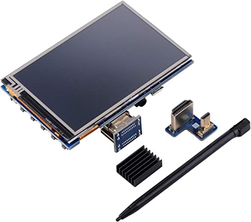
Raspberry displays
edit cmdline.txt
add "fbcon=map:10 fbcon=font:ProFont6x11 logo.nologo"
at the end
edit config.txt
add between custom comments at the bottom
dtoverlay=piscreen,speed=24000000,rotate=90
# Or check http://www.lcdwiki.com/3.5inch_RPi_Display
Above display’s i’ve used for Picore Players and the Lidar POC
To try: Getting above display running with a arduino
https://github.com/PaulStoffregen/XPT2046_Touchscreen
Raspberry HDMI display
Easiest of them all, just connect with HDMI, there is a adaptor for hdmi-hdmi (versions 1,2,3) and hdmi-mini-hdmi for RPi4 variants.
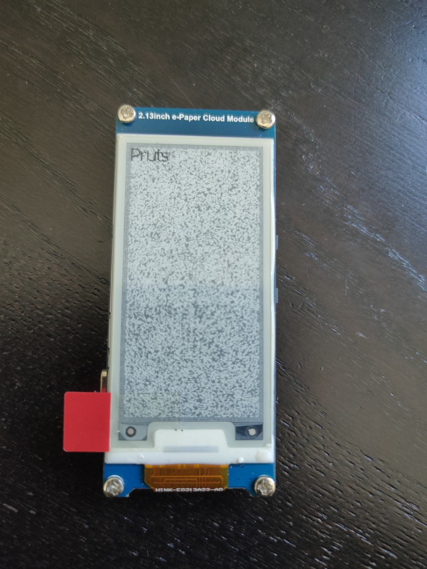
Epaper and 7-Segment displays
Other means of displaying information are for example
Epaper
7 Segment displays
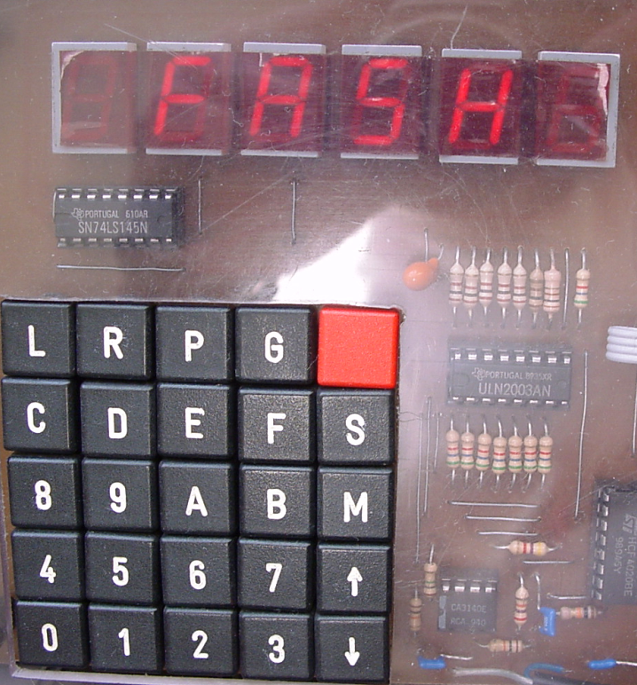
I used a lot of 7-Segment display’s in the past. They look cool and are hardcore.
My homebrew computer uses this
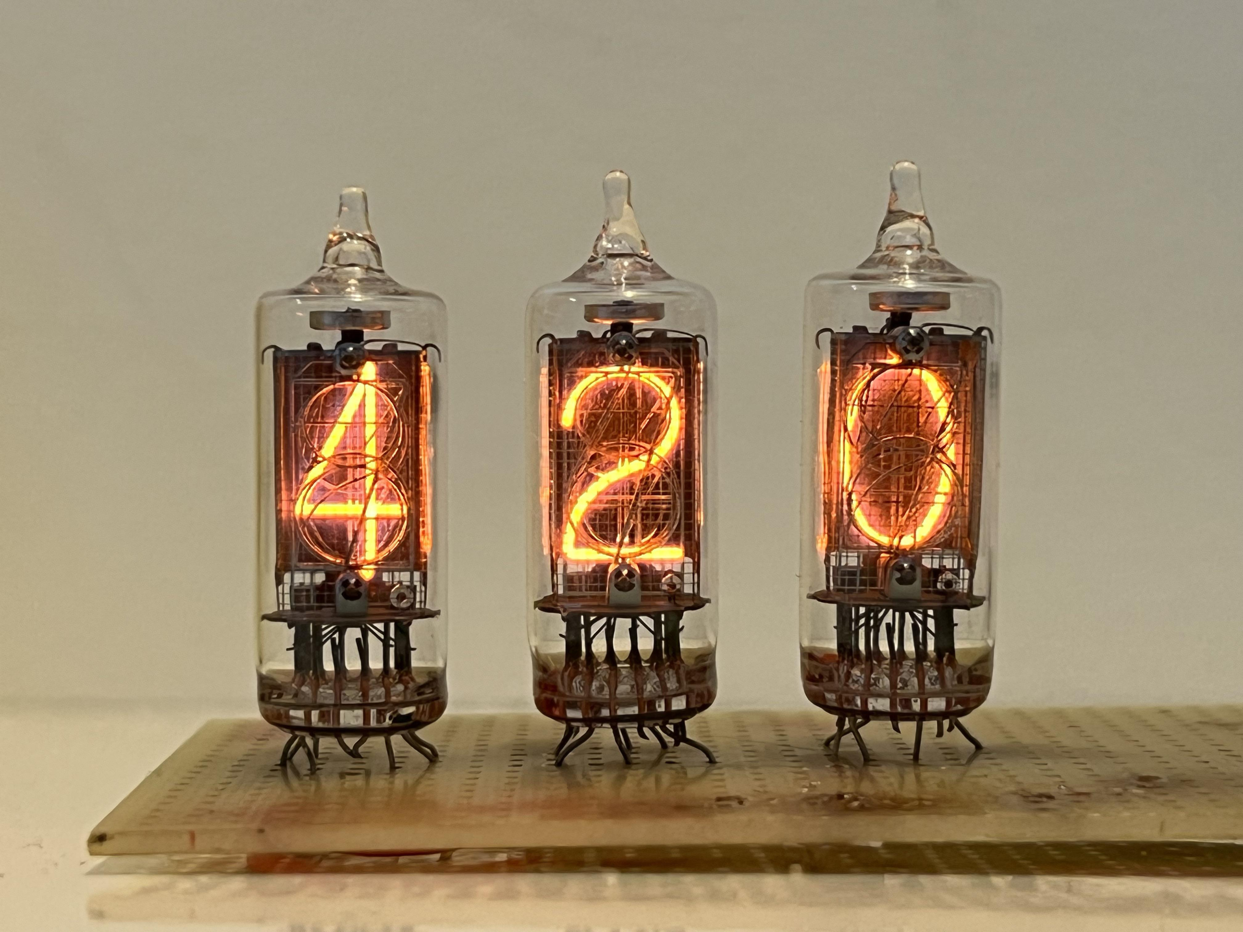
Nixie tubes!
And there are https://en.wikipedia.org/wiki/Nixie_tube .. I’ve never had those
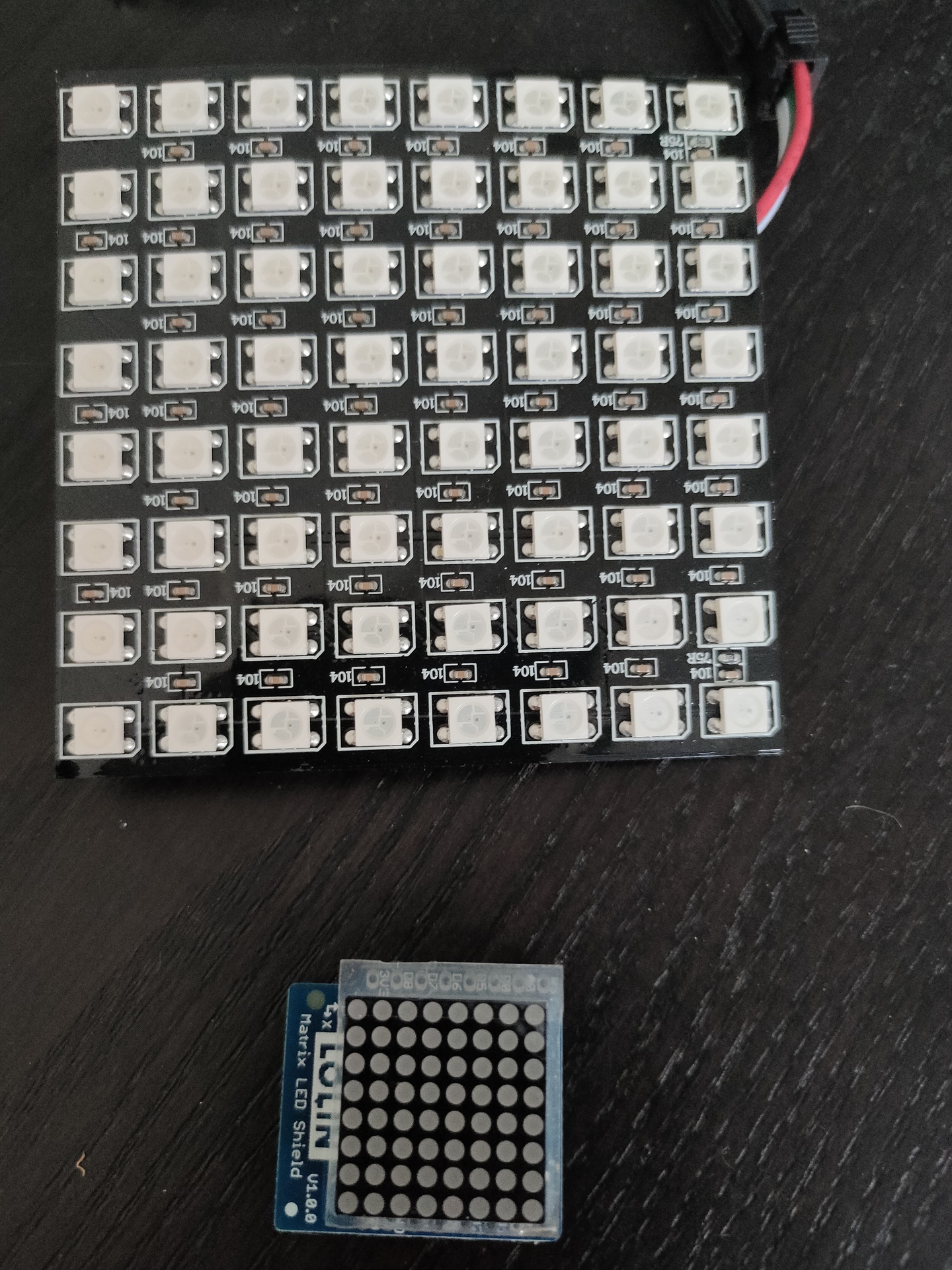
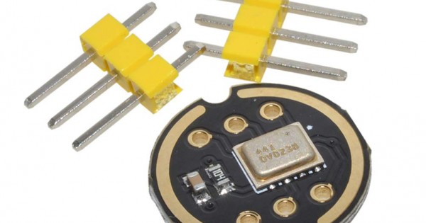
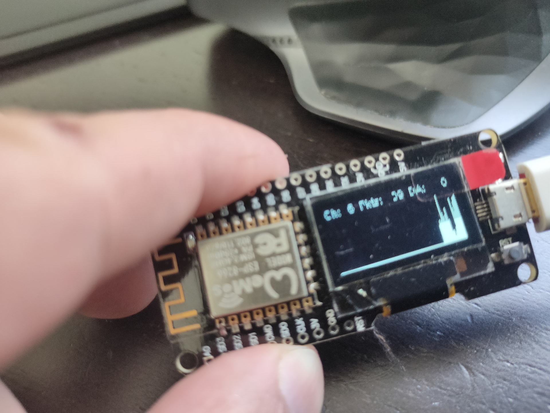
Above bigger 2D display i used with Wled and a digital microphone, so its sound reactive. The lower part i got in recently .