Designing a new, more flexible, midi controller
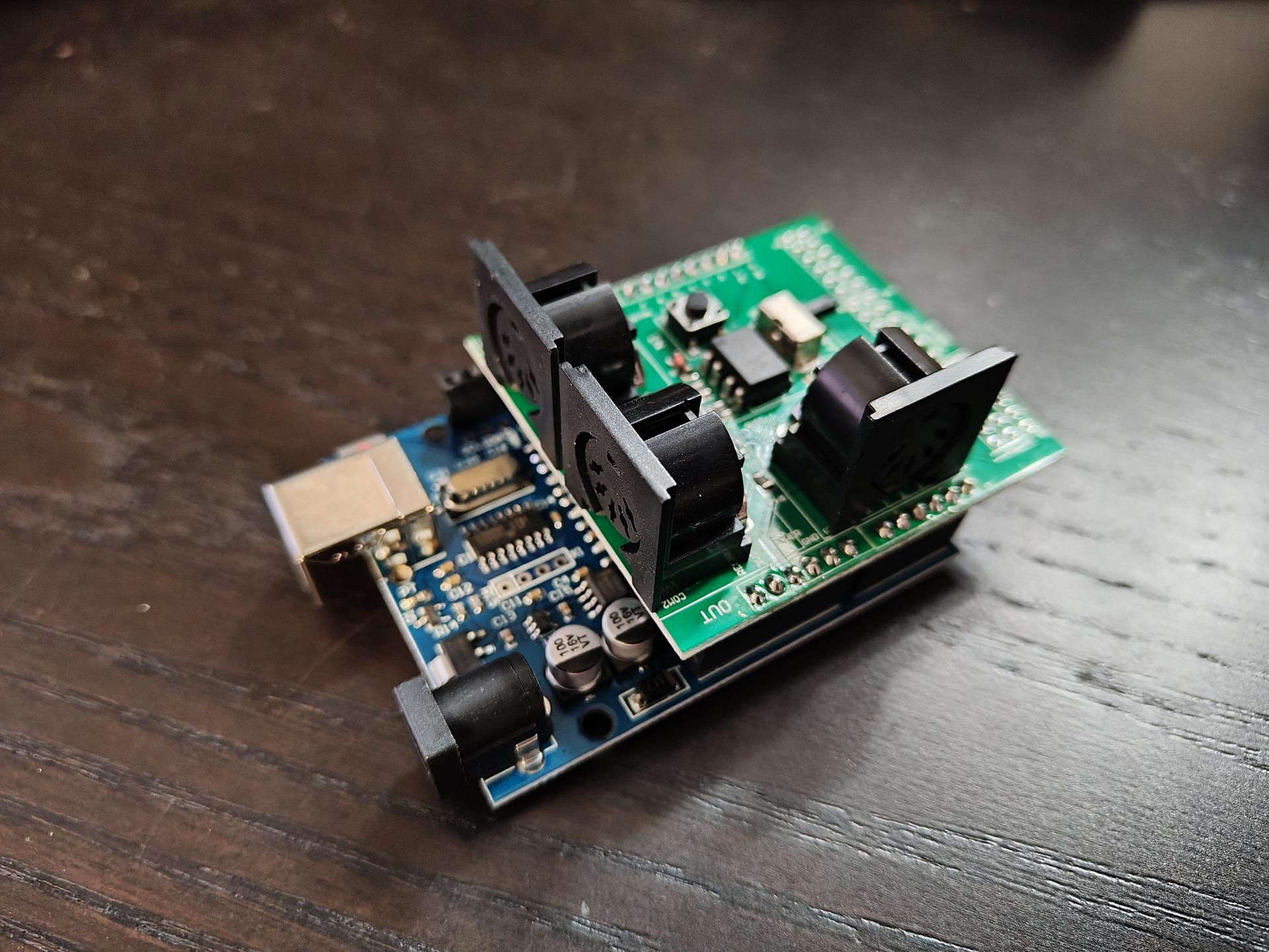
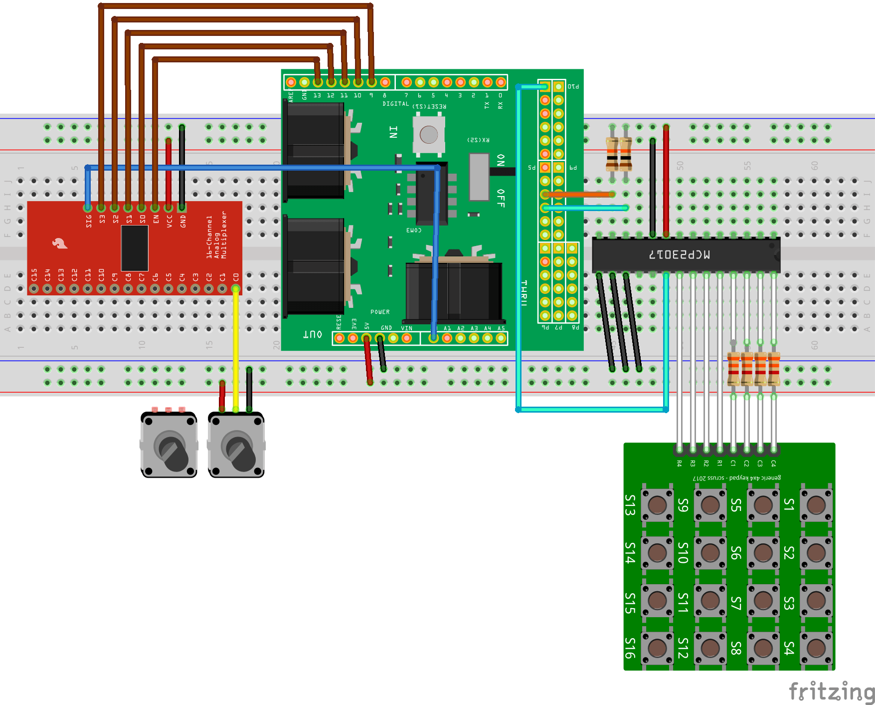
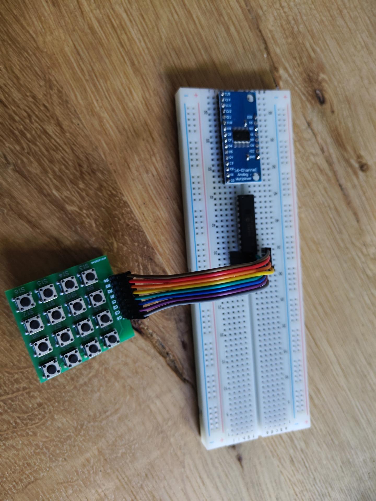
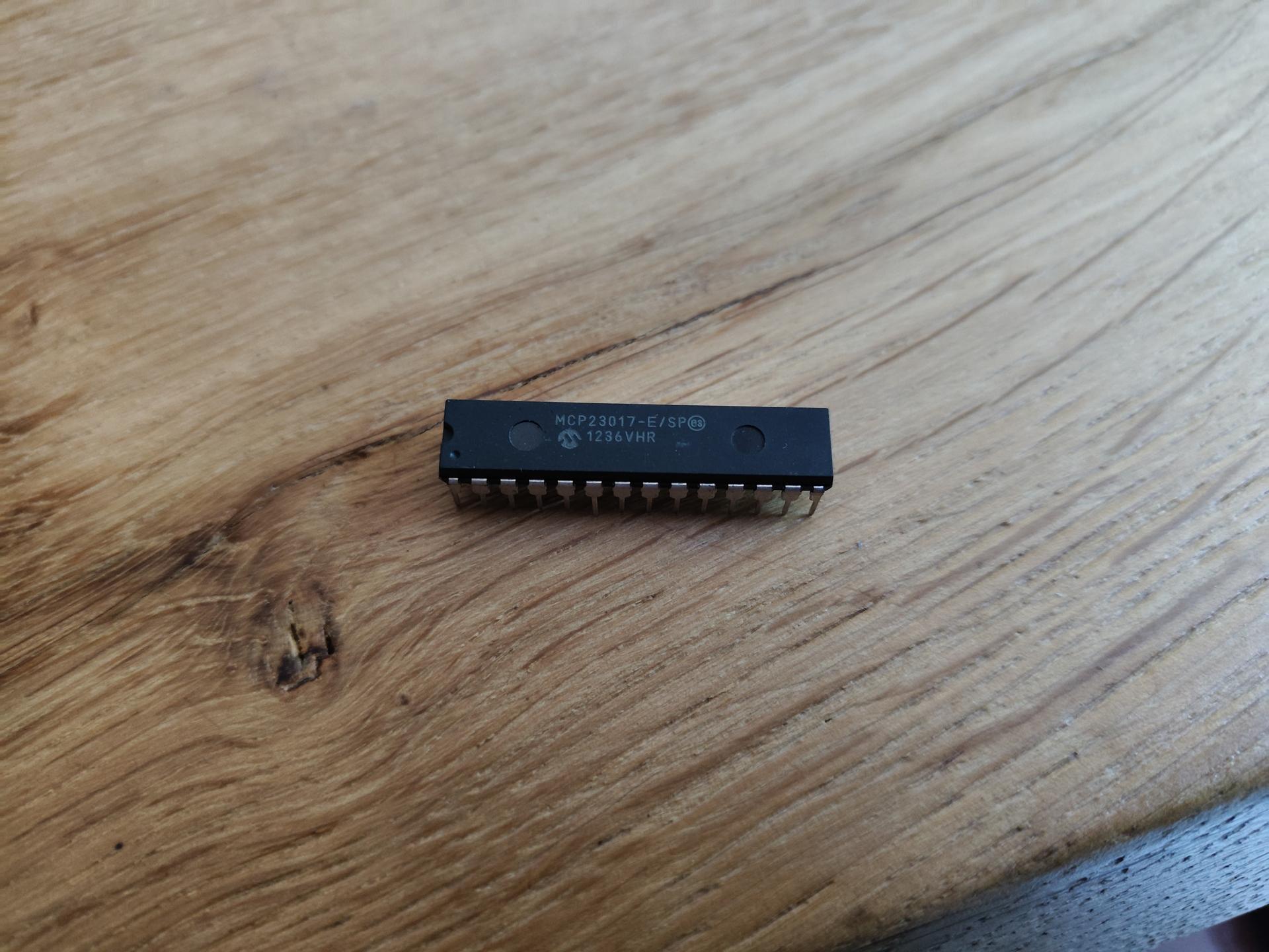
Analogue multiplexer for potentiometers, and MCP I2C IO extender for matrix keyboard.
Designing a new, more flexible, midi controller
Analogue multiplexer for potentiometers, and MCP I2C IO extender for matrix keyboard.
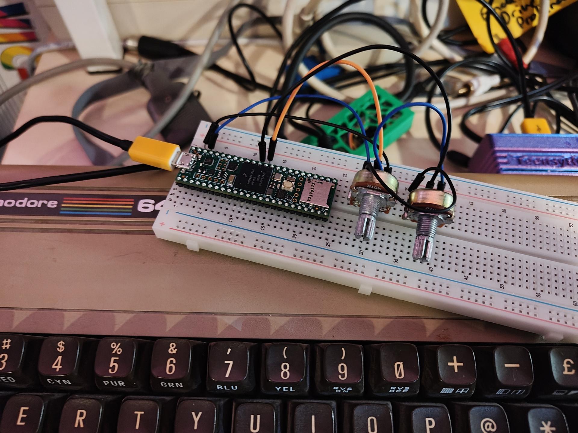
I bought a teensyrom a while ago.
Tyrone and I wanted to control the settings using potmeters.
So I grabbed a Teensy 4.1 controller and some 10K potmeters, some code using
Test code for two pots, don’t forget to set your USB mode to midi!
Schematic soon, also all tweaks and note sending.
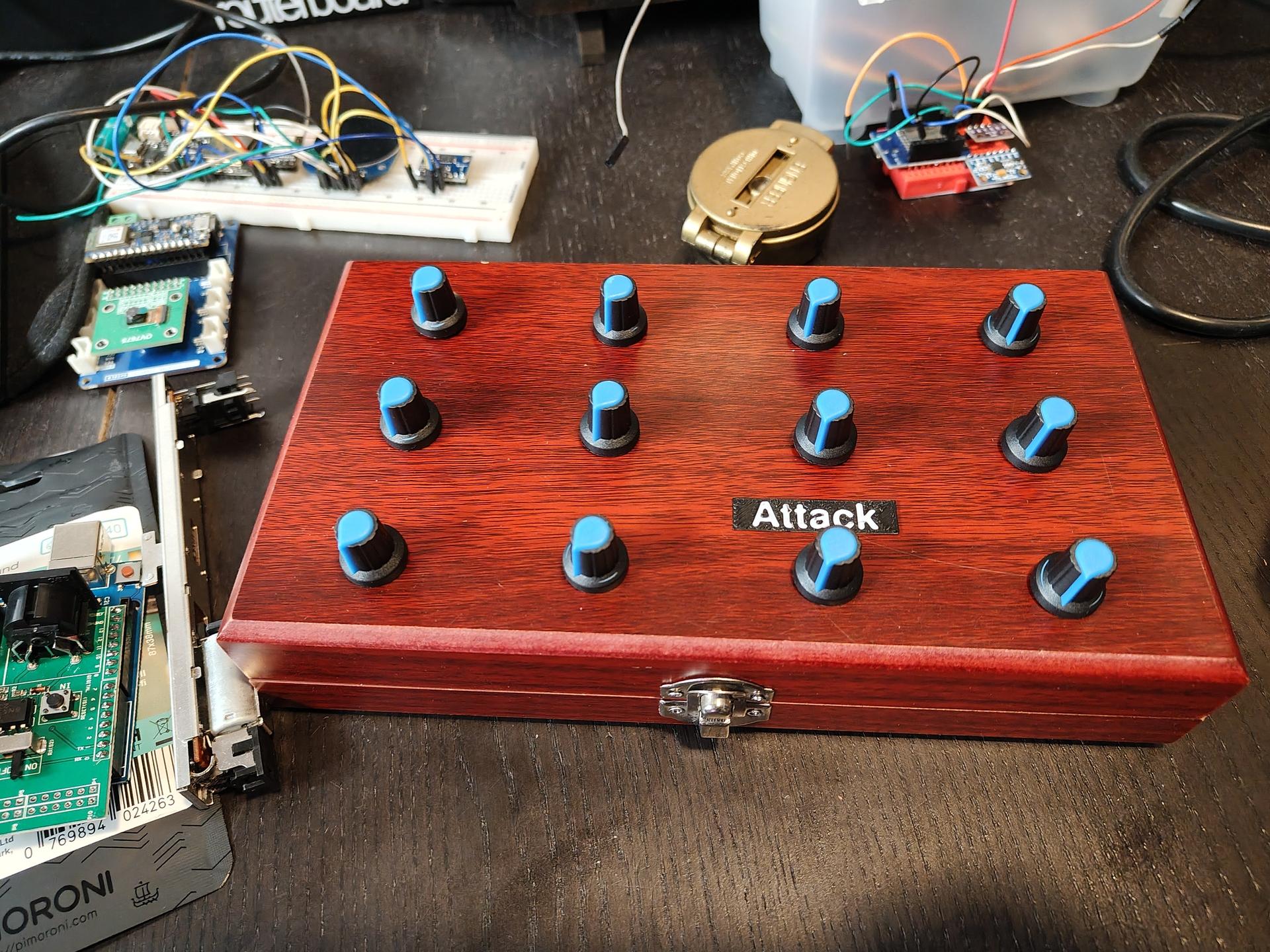
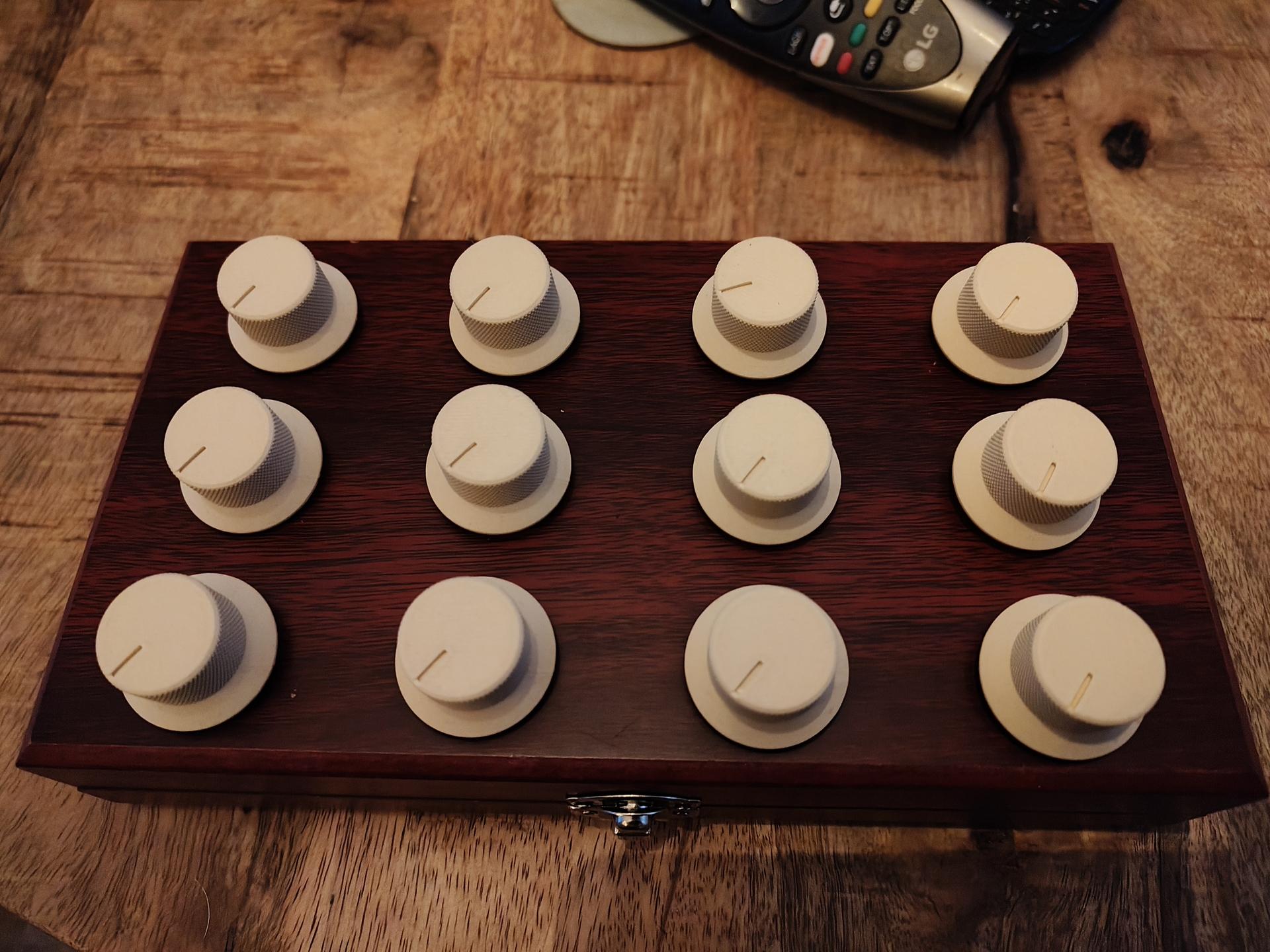
Next to do: 12 pots!
A nice case and extra buttons!
Let’s use an old box to hold the pots!
reconst int numPots = 12;

// Custom mappings:
const int potPins[numPots]     = {A0, A1, A2, A3, A4, A5, A6, A7, A8, A9, A10, A11};  // Analog pins
const int ccNumbers[numPots]   = {4, 8, 3, 4, 5, 6, 7, 8, 9, 10, 11, 12};             // CC numbers
const int midiChannels[numPots]= {2, 1, 1, 2, 2, 2, 3, 3, 3, 4, 4, 4};                // MIDI channels (1–16)

int lastValues[numPots];

void setup() {
  for (int i = 0; i < numPots; i++) {
    pinMode(potPins[i], INPUT);
    lastValues[i] = -1;
  }
}

void loop() {
  for (int i = 0; i < 2; i++) {
    int analogValue = analogRead(potPins[i]);
    int midiValue = analogValue / 8;  // Scale 0–1023 to 0–127

    if (abs(midiValue - lastValues[i]) > 1) {
      usbMIDI.sendControlChange(ccNumbers[i], midiValue, midiChannels[i]);
      lastValues[i] = midiValue;
    }
  }

  delay(5);
}
I’ve got my own chat server, because WhatsApp sucks.
With this I can play around.
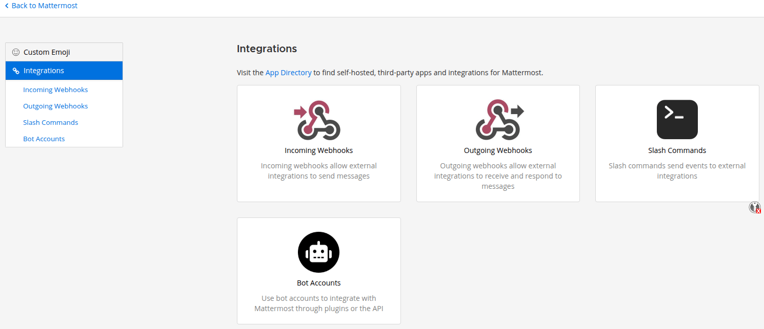
Below is a script to capture an image from a (Reolink) webcam, and show this in a Mattermost channel.
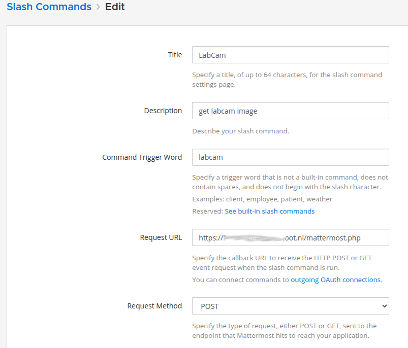
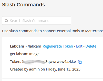
You need to configure your /slash command in Mattermost and a webserver with PHP
When entering
/labcam
in a channel, an image will be shown.
Code:
<?php

// See token from screenshots above
$expected_token = 'YOUR_MATTERMOST_TOKEN';
$token = $_POST['token'] ?? '';

if ($token !== $expected_token) {
    http_response_code(403);
    echo 'Invalid token, go away';
    exit;
}


// Reolink camera settings
$ip = '192.168.1.2'; // Replace with your camera IP
$user = 'admin';       // Camera username
$pass = 'admin';// Camera password
$rs = uniqid();        // Unique request string

$url = "http://$ip/cgi-bin/api.cgi?cmd=Snap&channel=0&rs=$rs&user=$user&password=$pass";

// Temporary image save path (ensure this directory is public and writable)
$image_filename = 'snapshot_' . time() . '.jpg';
$image_path = __DIR__ . '/snapshots/' . $image_filename;  // e.g., public_html/snapshots/
$image_url = 'https://labcam.henriaanstoot.nl/snapshots/' . $image_filename; // Public URL

// Fetch image from Reolink using cURL
$ch = curl_init($url);
curl_setopt($ch, CURLOPT_RETURNTRANSFER, true);
curl_setopt($ch, CURLOPT_FOLLOWLOCATION, true);
curl_setopt($ch, CURLOPT_HEADER, false);
curl_setopt($ch, CURLOPT_HTTPAUTH, CURLAUTH_BASIC);
curl_setopt($ch, CURLOPT_USERPWD, "$user:$pass");
$image_data = curl_exec($ch);
$http_code = curl_getinfo($ch, CURLINFO_HTTP_CODE);
curl_close($ch);

if ($http_code !== 200 || !$image_data) {
    echo json_encode([
        'response_type' => 'ephemeral',
        'text' => 'Failed to get snapshot from Reolink camera.',
    ]);
    exit;
}

// Save image
file_put_contents($image_path, $image_data);

// Respond to Mattermost
$response = [
    'response_type' => 'in_channel',
    'text' => 'Live snapshot from camera:',
    'attachments' => [[
        'image_url' => $image_url,
        'fallback' => 'Reolink snapshot'
    ]]
];

header('Content-Type: application/json');
echo json_encode($response);
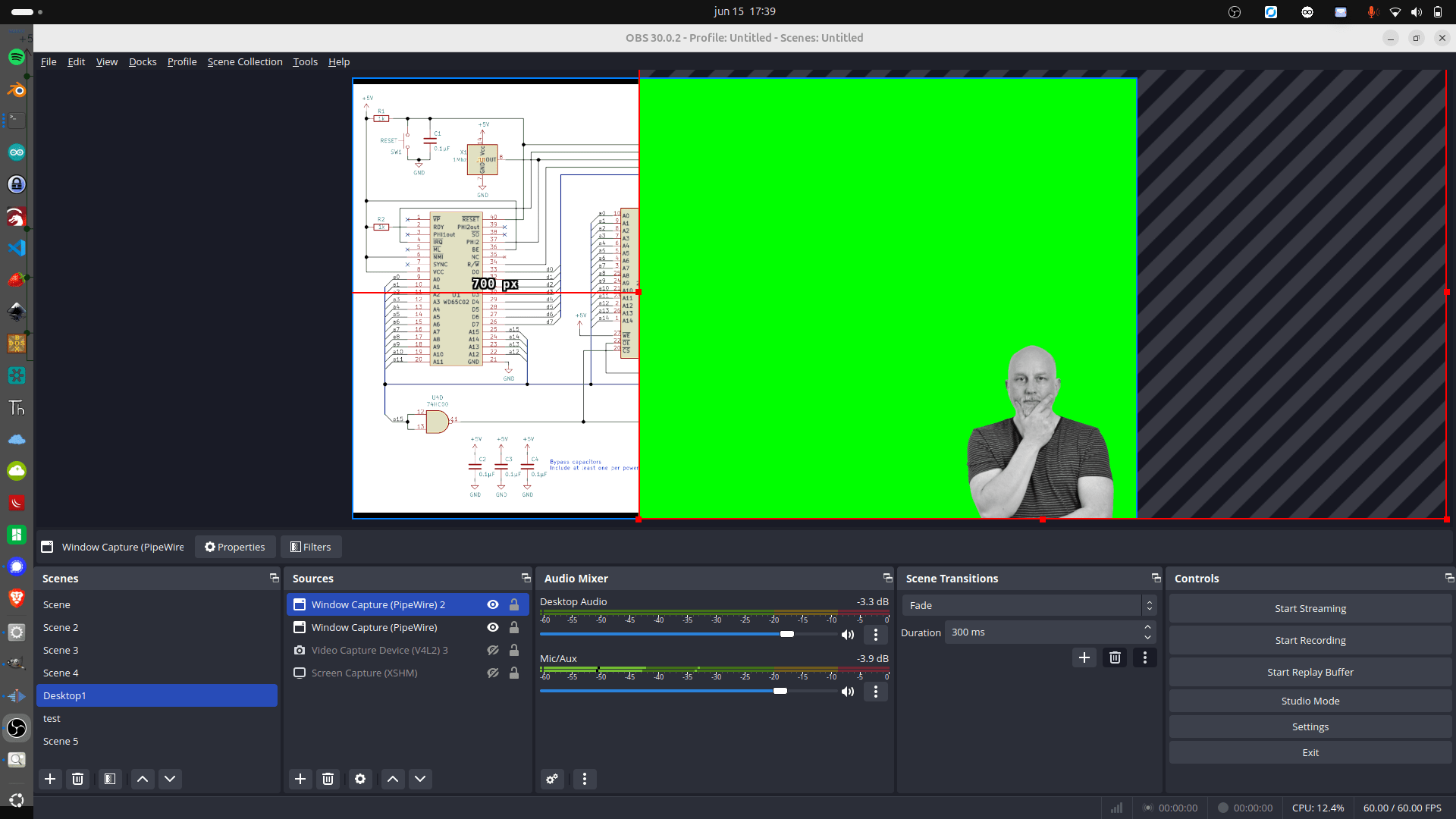
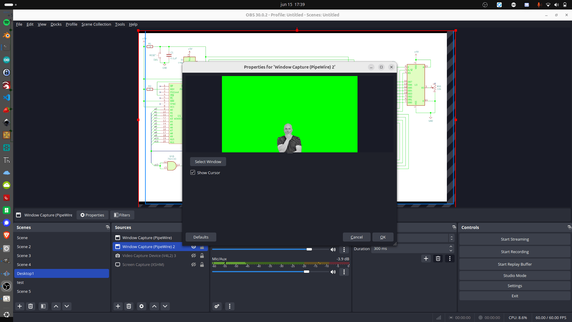
I use OBS sometimes to explain things, I thought it would be nice to have a moving avatar thingy in my screencast which moves when I talk.
The image is a transparent PNG, and I’m moving it up and down using the microphone and a python script.

CODE:
import pygame
import pyaudio
import numpy as np
import sys

# Settings
PNG_PATH = "your_image.png"  # Replace with your transparent PNG path
CHUNK = 1024
FORMAT = pyaudio.paInt16
CHANNELS = 1
RATE = 44100
MOVEMENT_THRESHOLD = 1
GRAVITY = 3 # Tweak this, to get smoother "talk" bounch
JUMP_MULTIPLIER = 3  # Controls jump power Tweak this shit
MAX_JUMP_HEIGHT = 30   # Max  bounce
START_OFFSET = -450      # How far below screen the PNG starts ( so my avator stays covered in bottom )

# Initialize PyAudio
p = pyaudio.PyAudio()
stream = p.open(format=FORMAT,
                channels=CHANNELS,
                rate=RATE,
                input=True,
                frames_per_buffer=CHUNK)

# Initialize Pygame
pygame.init()
info = pygame.display.Info()
screen_width, screen_height = info.current_w, info.current_h
screen = pygame.display.set_mode((screen_width, screen_height), pygame.FULLSCREEN)
pygame.display.set_caption("Mic Bounce PNG")

# Load image
image = pygame.image.load(PNG_PATH).convert_alpha()
img_rect = image.get_rect()
img_rect.centerx = screen_width // 2
img_rect.top = screen_height + START_OFFSET  # Start below the screen

velocity_y = 0
clock = pygame.time.Clock()

def get_loudness():
    data = np.frombuffer(stream.read(CHUNK, exception_on_overflow=False), dtype=np.int16)
    volume = np.linalg.norm(data)
    return volume / CHUNK

# Bottom and top bounce limits
bottom_y = screen_height + START_OFFSET
top_y = screen_height + START_OFFSET - MAX_JUMP_HEIGHT

try:
    while True:
        for event in pygame.event.get():
            if event.type == pygame.QUIT or \
               (event.type == pygame.KEYDOWN and event.key == pygame.K_ESCAPE):
                raise KeyboardInterrupt

        loudness = get_loudness()

        if loudness > MOVEMENT_THRESHOLD and img_rect.top >= bottom_y:
            # Jump upward with capped power
            velocity_y = -int(min((loudness - MOVEMENT_THRESHOLD) * JUMP_MULTIPLIER, MAX_JUMP_HEIGHT))

        # Apply gravity
        velocity_y += GRAVITY
        img_rect.y += velocity_y

        if img_rect.top >= bottom_y:
            img_rect.top = bottom_y
            velocity_y = 0

        if img_rect.top <= top_y:
            img_rect.top = top_y
            velocity_y = 0

        # Draw chromakey green background
        screen.fill((0, 255, 0))

        # Draw PNG
        screen.blit(image, img_rect)

        pygame.display.flip()
        clock.tick(60)

except KeyboardInterrupt:
    stream.stop_stream()
    stream.close()
    p.terminate()
    pygame.quit()
    sys.exit()
Got some bluetooth beacons in the mail.
The plan is to hide these in the woods, and children have to find them using a scanner device.
Using a ESP32 with bluetooth, using RSSI (strength of signal) I can limit the range of detection.
The order of finding the tags is important, so a hidden tag should not be found when another should be found first.
These tags, hidden in toys, should be placed in a treasure chest.
(In order)
Then lights and sounds should hint the kids that they have successfully completed the mission.
So same detecting but even shorter range ESP is hidden in the Chest.
Some leds or a single blinking one should give hints about the distance of the object.
=== Matching iTags ===
MAC: 5b:08:10:4d:2a:01 | RSSI: -47
MAC: 5b:45:aa:0d:f7:9c | RSSI: -31 #### NEAR
MAC: 5b:88:fc:fc:e8:a9 | RSSI: -94 #### FAR AWAY
MAC: 5b:8b:00:00:1d:40 | RSSI: -66
Some test code:
#include <BLEDevice.h>
#include <BLEUtils.h>
#include <BLEScan.h>
#include <BLEAdvertisedDevice.h>

int scanTime = 5; // seconds
BLEScan* pBLEScan;

void setup() {
  Serial.begin(115200);
  Serial.println("Starting BLE scan...");

  BLEDevice::init("");
  pBLEScan = BLEDevice::getScan();
  pBLEScan->setActiveScan(true);
  pBLEScan->setInterval(100);
  pBLEScan->setWindow(99);
}

void loop() {
  BLEScanResults results = *pBLEScan->start(scanTime, false);
  Serial.println("=== Matching iTags ===");

  for (int i = 0; i < results.getCount(); i++) {
    BLEAdvertisedDevice device = results.getDevice(i);
    String mac = device.getAddress().toString();

    if (mac.startsWith("5b:")) {
      Serial.print("MAC: ");
      Serial.print(mac);
      Serial.print(" | RSSI: ");
      Serial.println(device.getRSSI());
    }
  }

  Serial.println("======================");
  pBLEScan->clearResults();
  delay(2000);
}
This weekend we went to Nerdland in Belgium.
I saw a cool game when we had to wait before some talks started.

What is so special about pong?
Well, half of the audience was playing the other part of the audience.
250 against 250 Multiplayer.
It used mqtt websockets, and the audience mobile phones with tilting.
Average of 33+ % choosing up? Paddle goes up, Center and down the same.
I think I can make it myself.
So below my two days progression.
MQTT via internet.
Sound and score counter.
Using the mobile phone’s tilt sensor.
Maybe I’m going to change it into some 3D maze game.
Code soon
A friend came with a locked phone.
His son had changed the swipe lock thingy, and forgot what it was,
How I recovered Pictures and Movies:
ADB was turned off, and MTP doesn’t work when locked.
Phone was one of the below.
MT6781, MT6789, MT6855, MT6886, MT6895, MT6983, MT8985
git clone https://github.com/bkerler/mtkclient
cd mtkclient
pip3 install -r requirements.txt
./python3 mtk.py rl test
Press Volume up and volume down and keep pressed.
Now connect the USB cable.
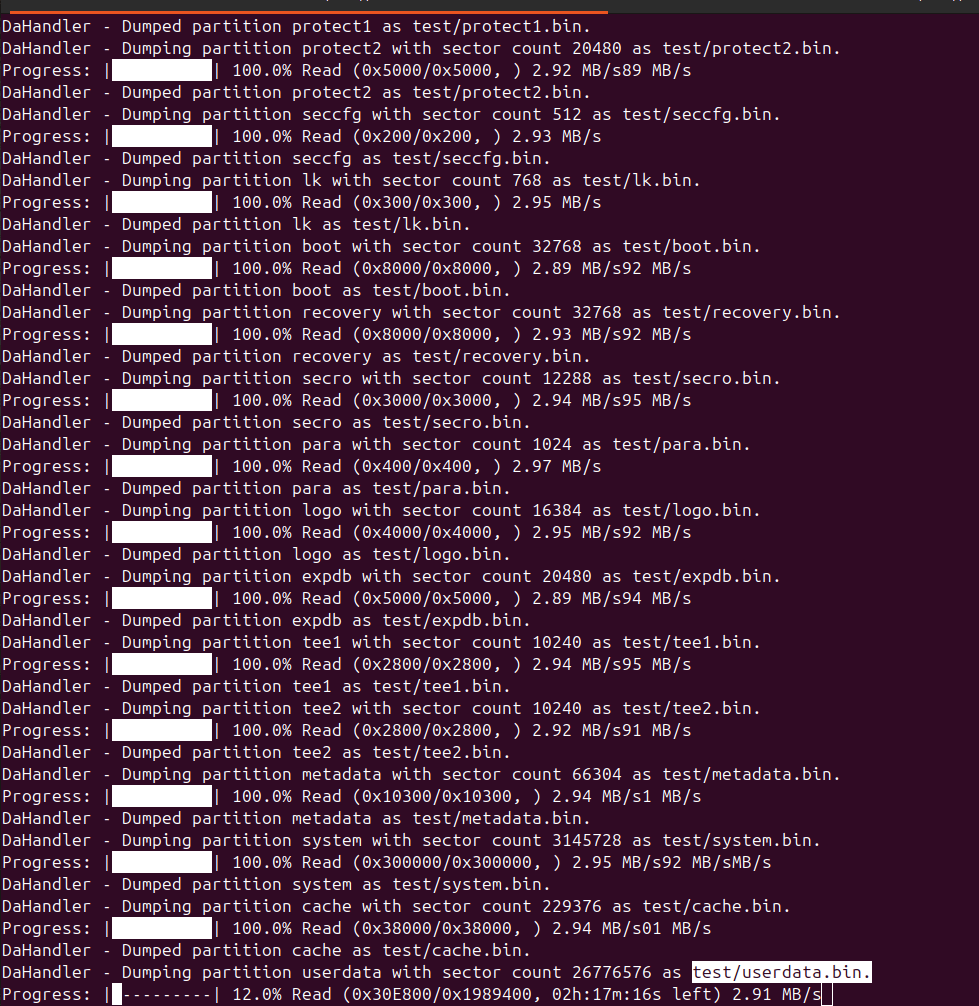
Partitions are downloading, we need userdata.bin
This takes a while!
Next: Extract data
Install Guestfish
sudo guestfish --ro -a userdata.bin
<fs>
run
list-filesystems
mount /dev/sda /
ls /
glob copy-out /media/0/DCIM/Camera/* .
Data extracted and phone was still locked.
That’s all that was needed, factory reset was next.
I was planning to make a RSS reader using this display, but I came across a weather display project I wanted to check out.
(So I probably end up buying another one)
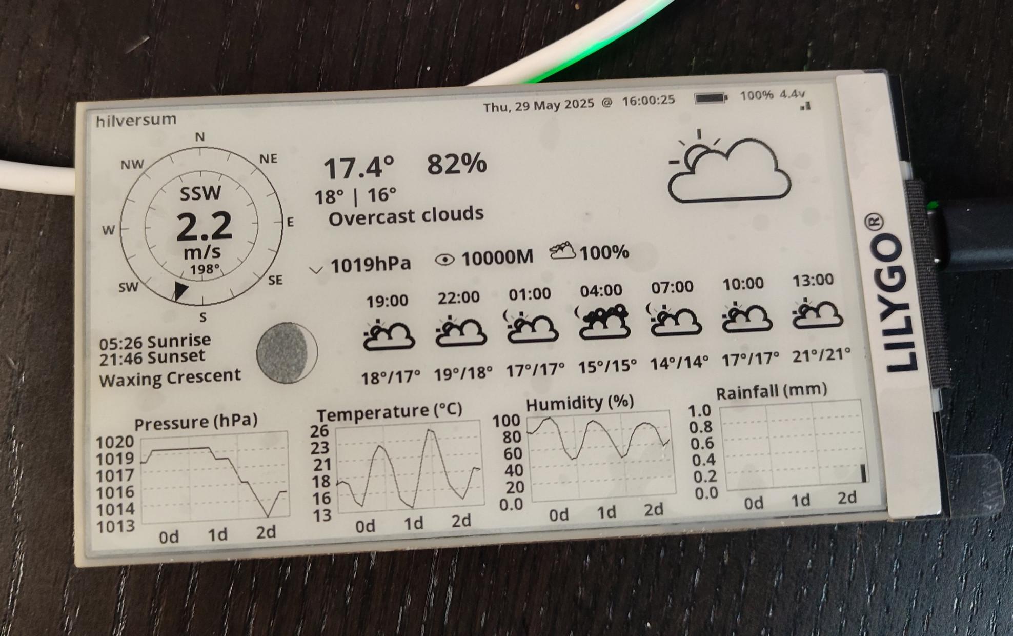
There are many questions and issues around this project using the S3.
So here is my solution.
Install vscode
Goto plugins and install platformio
git clone https://github.com/Xinyuan-LilyGO/LilyGo-EPD-4-7-OWM-Weather-Display.git
Warning this is NOT the branch you want to use
git checkout web
(git pull)
open directory in code
open platformio.ini and change line 13
default_envs = T5_4_7Inc_Plus_V2
(If needed add upload_port = /dev/tty**** at the end)
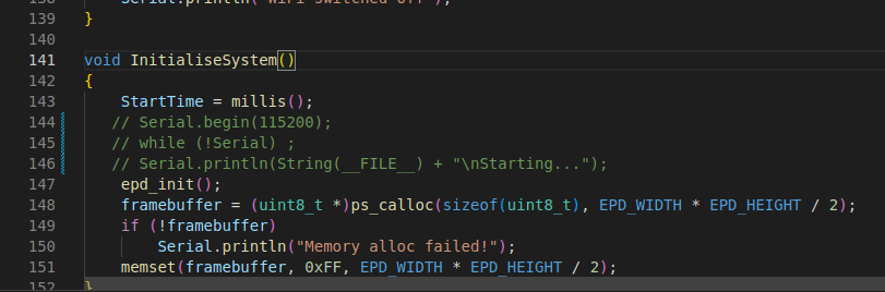
Change INO file lines 144-146.
Comment serial out, else update won’t work using regular power or battery.
When saving this platformio.ini file, some downloading and installing should be popping up.
When issues occur about libraries see below.
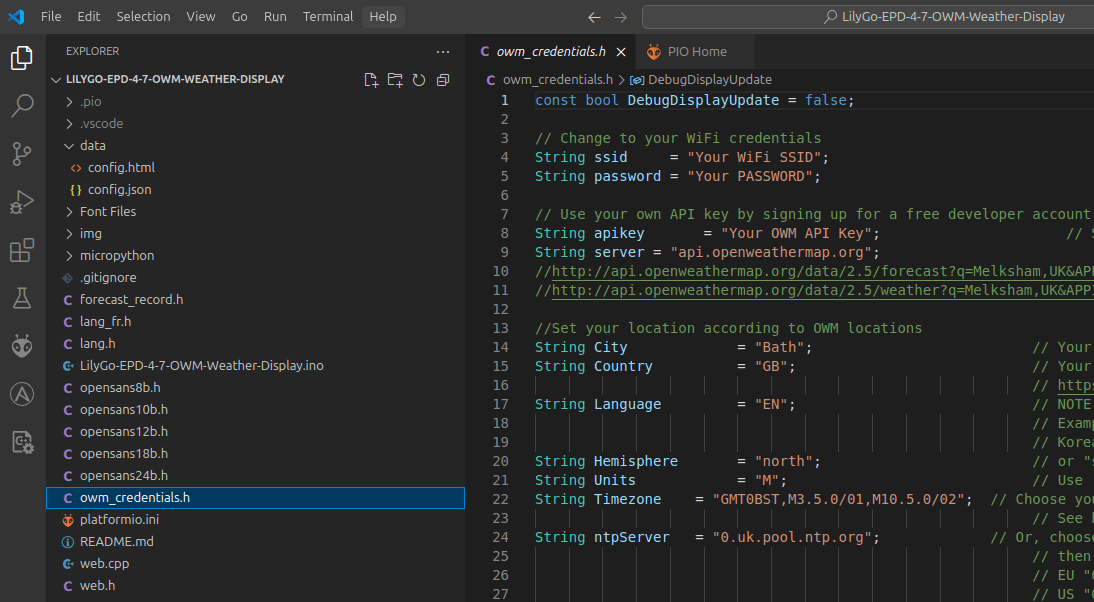
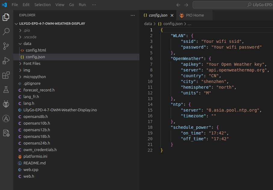
Fill out
data>config.json
and owm_credentials.h to be sure.
(use owm_credentials information to fill config.json)
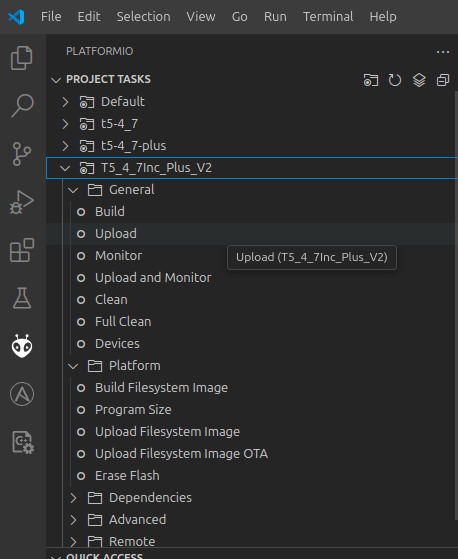
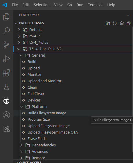
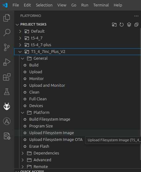
Next press the platformio icon
Fix for uploading:
Press and hold STR_IO0 button
Press REST button
Release STR_IO0 button
Libraries:
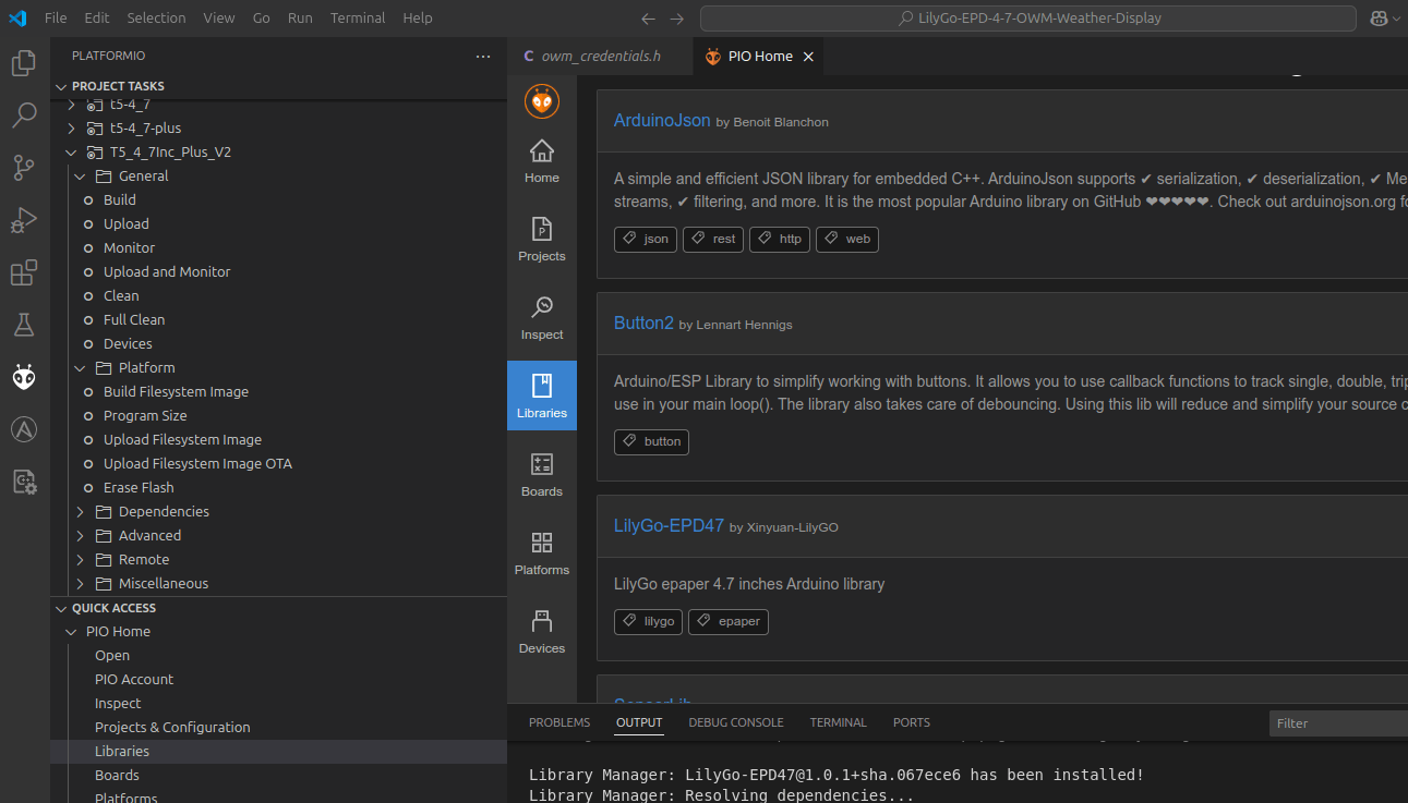
Press platformio icon, libaries and install ArduinoJson, Button2 and LilyGo-EPD47 (select your project while doing so!)
Note: Per default once per hour update, change if you want to.
Line 70 in the INO file
Build/Upload errors? .. Press clean to recompile using a clean state !
I like animatronics.
In the past, I made animatronics using :
Windscreen wipers, Servo controllers and stepper motors.
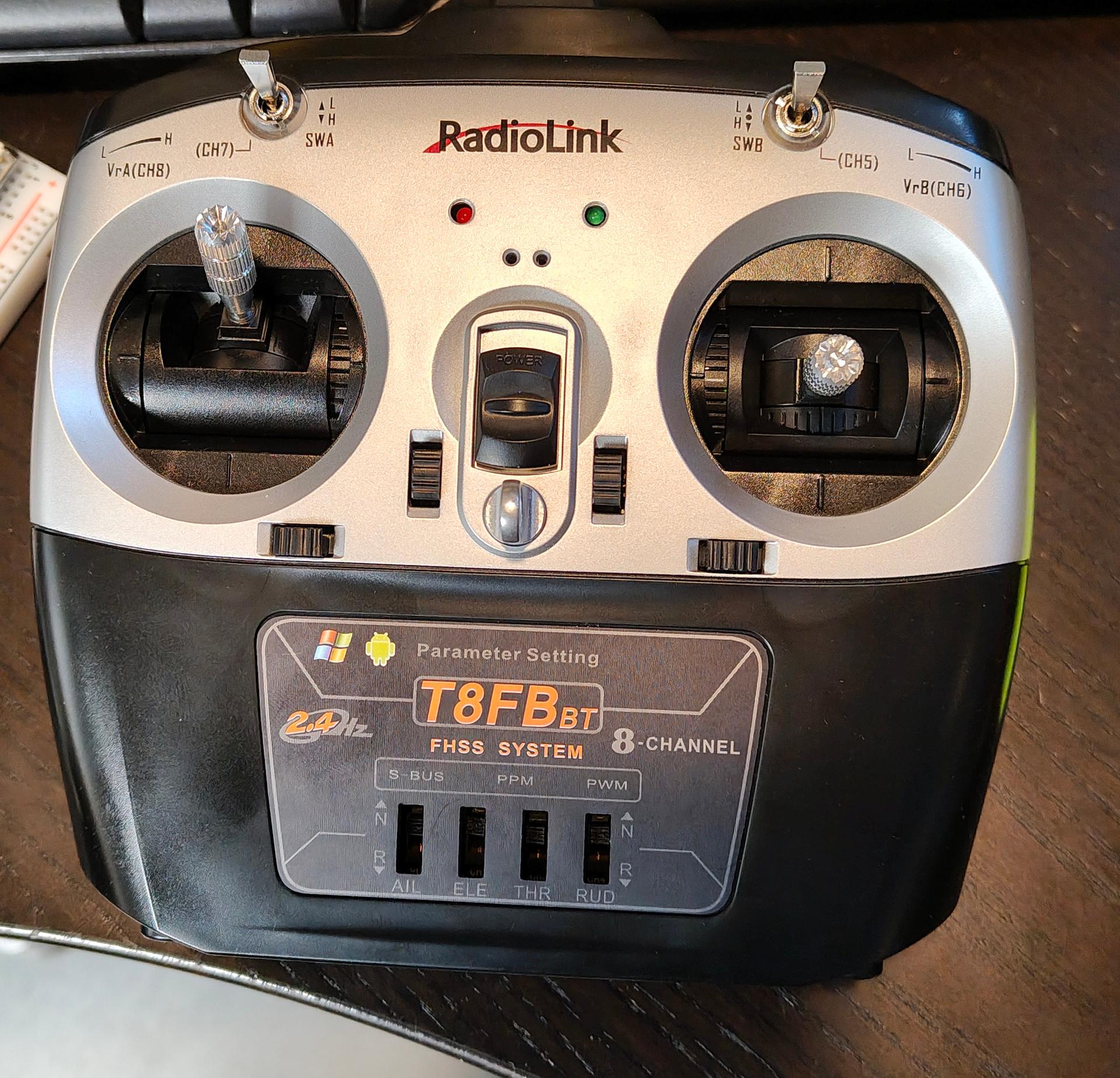
I bought a new controller with an 8 channel receiver. Now I can manually control and test setups.
I altered and 3D printed this model from Will Cogley
Now I have to make this more programmable, python on a RPi should do it.
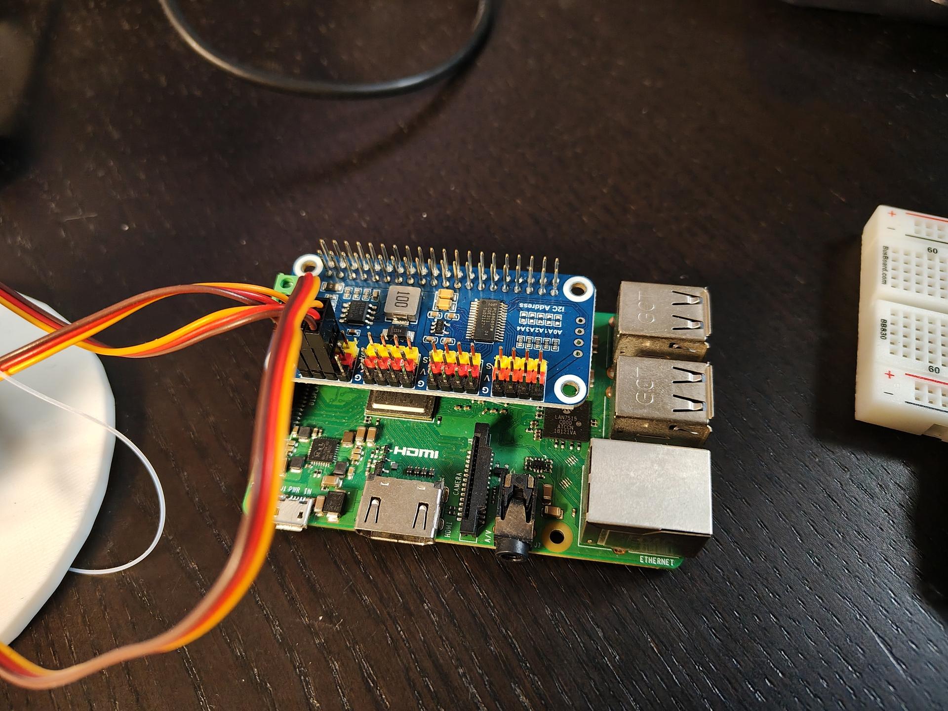
Planning to use a 360 degrees lidar, so the eyes can follow you around.
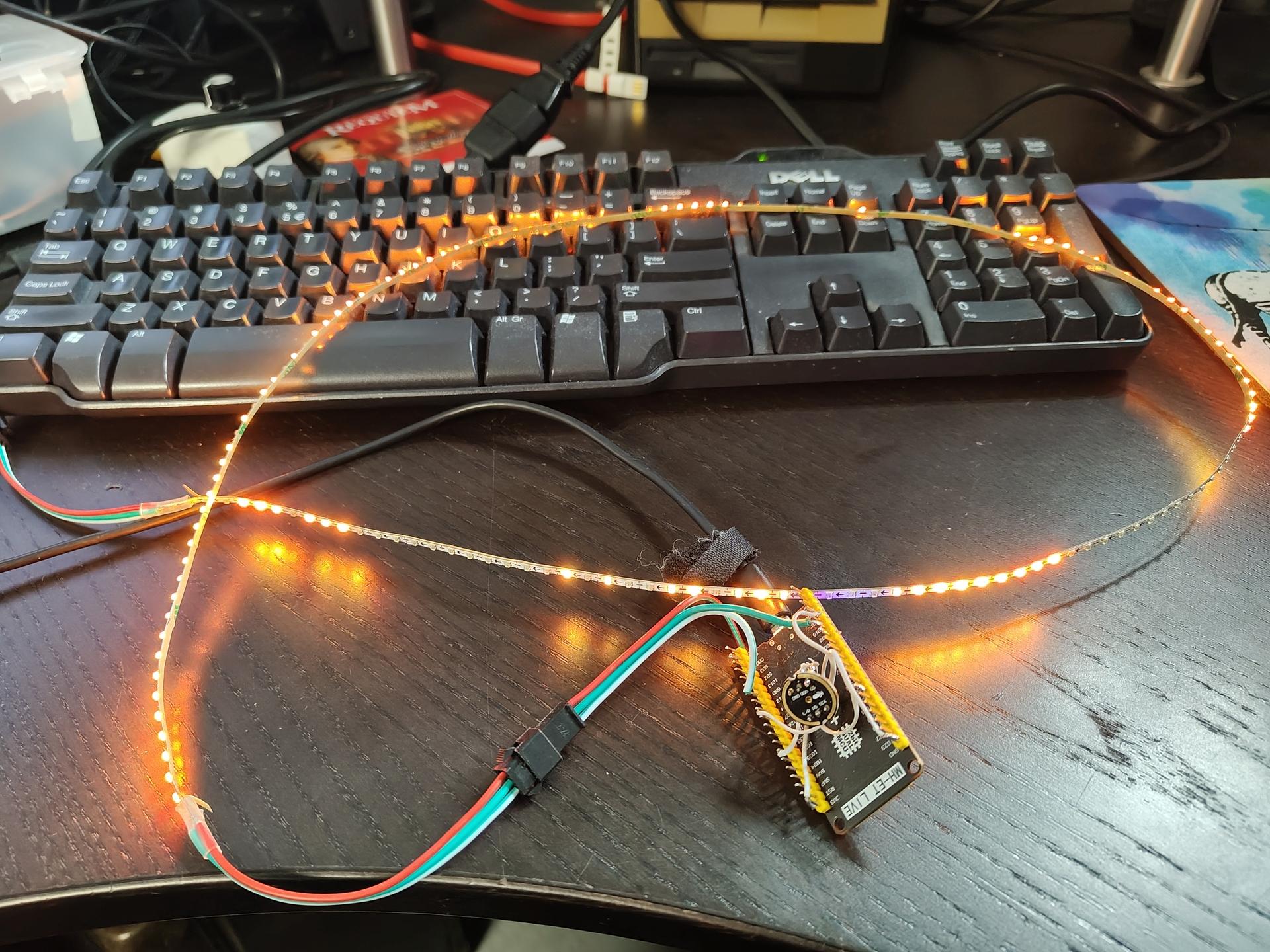
I got some other new stuff in also:
Some 360 degrees servo’s and a mini led strip which a connected to a WLED with digital I2S microphone.
Below is my python script to push messages via pushover to my phone.
It’s being run from a cron during the day.
CODE
import csv
import datetime
import requests

# configure own creds
PUSHOVER_USER_KEY = 'keykeykeykeykeykeykeykey'
PUSHOVER_API_TOKEN = 'tokentokentokentokentokentokentoken'
CSV_FILE = '/data/notifications.csv'

def send_pushover_notification(message):
    url = "https://api.pushover.net/1/messages.json"
    payload = {
        "token": PUSHOVER_API_TOKEN,
        "user": PUSHOVER_USER_KEY,
        "message": message
    }
    response = requests.post(url, data=payload)
    if response.status_code != 200:
        print("Failed to send notification:", response.text)

def check_and_notify():
    today = datetime.date.today()
    with open(CSV_FILE, newline='') as csvfile:
        reader = csv.DictReader(csvfile)
        for row in reader:
            try:
                day = int(row['day'])
                month = int(row['month'])
                if today.day == day and today.month == month:
                    send_pushover_notification(row['message'])
            except ValueError:
                continue

if __name__ == "__main__":
    check_and_notify()
notifications.csv file
day,month,message
1,1,Birthday of a new year
16,05,Project Deadline
16,05,Test2 (blah) 2
7,3,Glorious bastard Rik Mayall birthday
27,3,International whisky day
Nice to haves (didn’t implement because i’m a lazy bastard)