Deeply impressed by your blog content which means a lot to electronic enthusiasts.
I'd like to sponsor your project by providing free PCB prototyping,
ROM SWITCHER
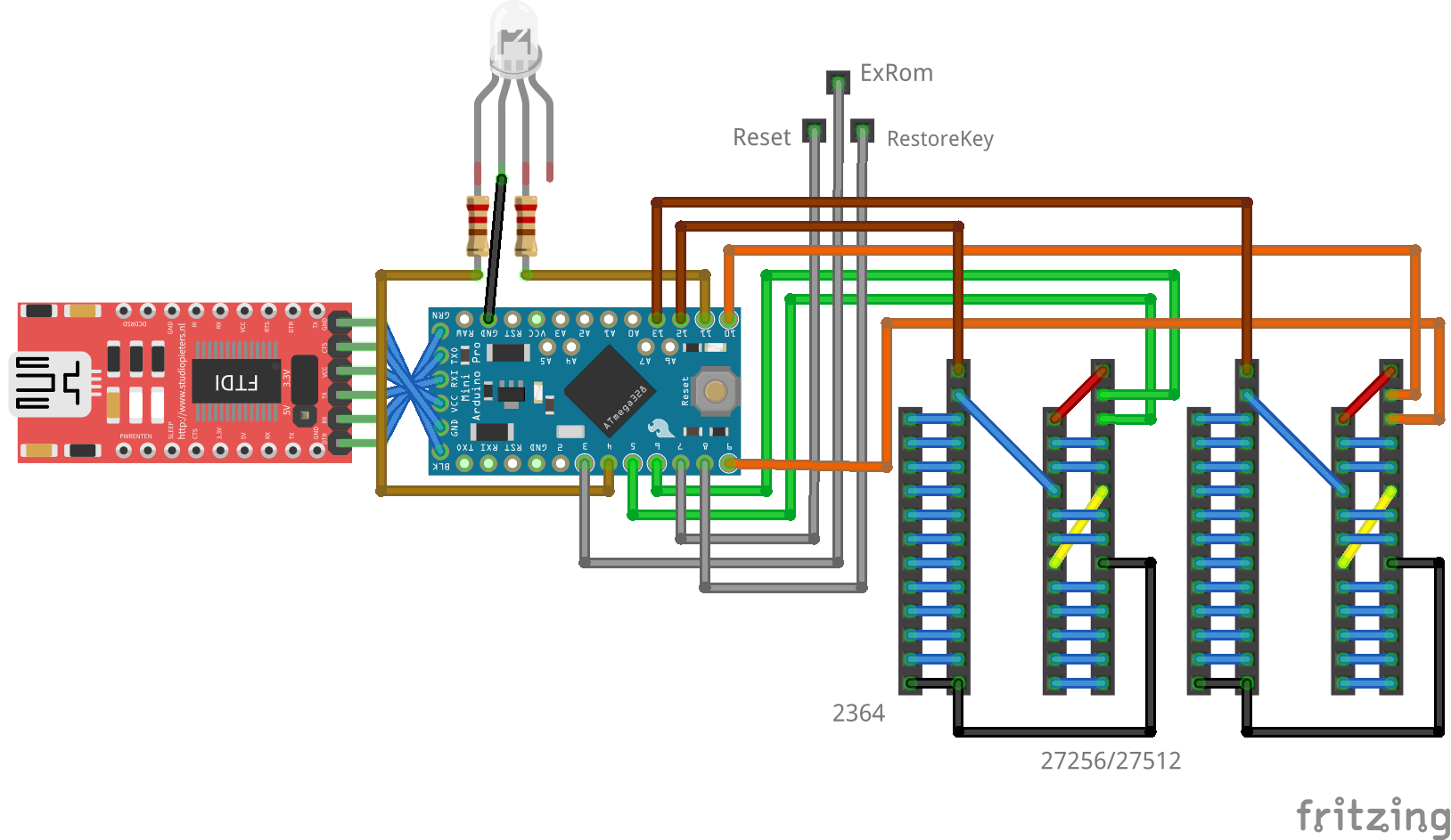
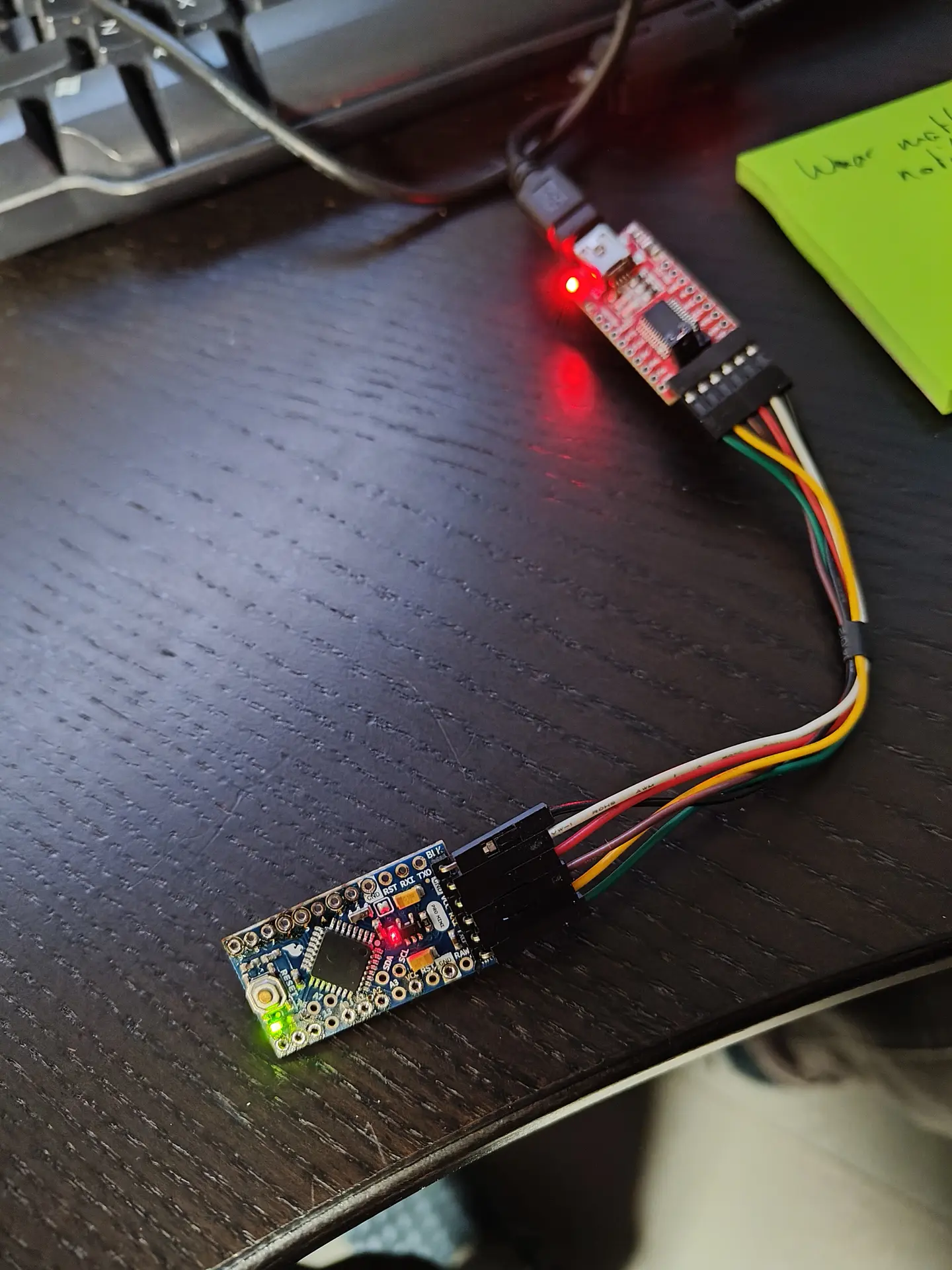
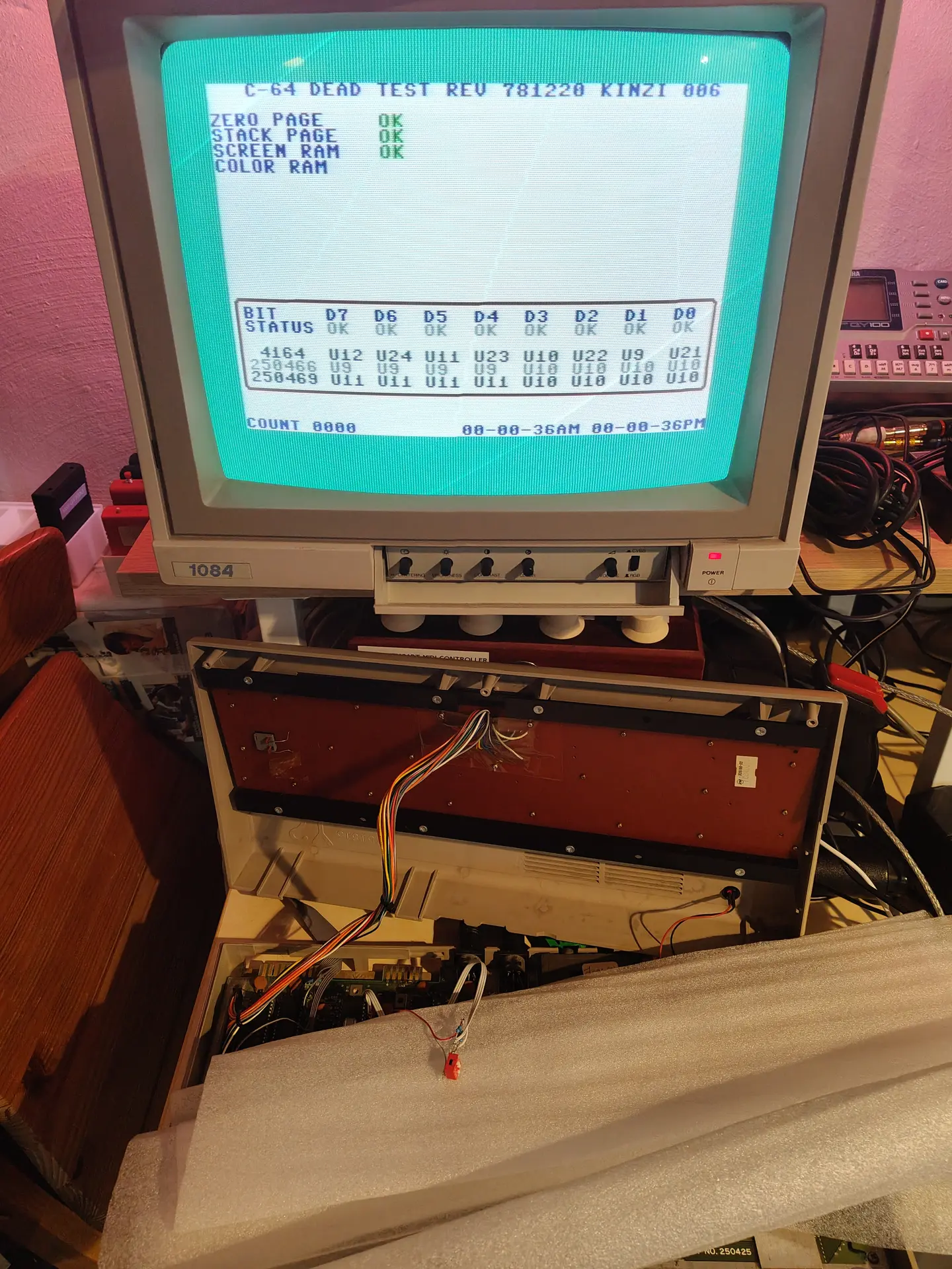
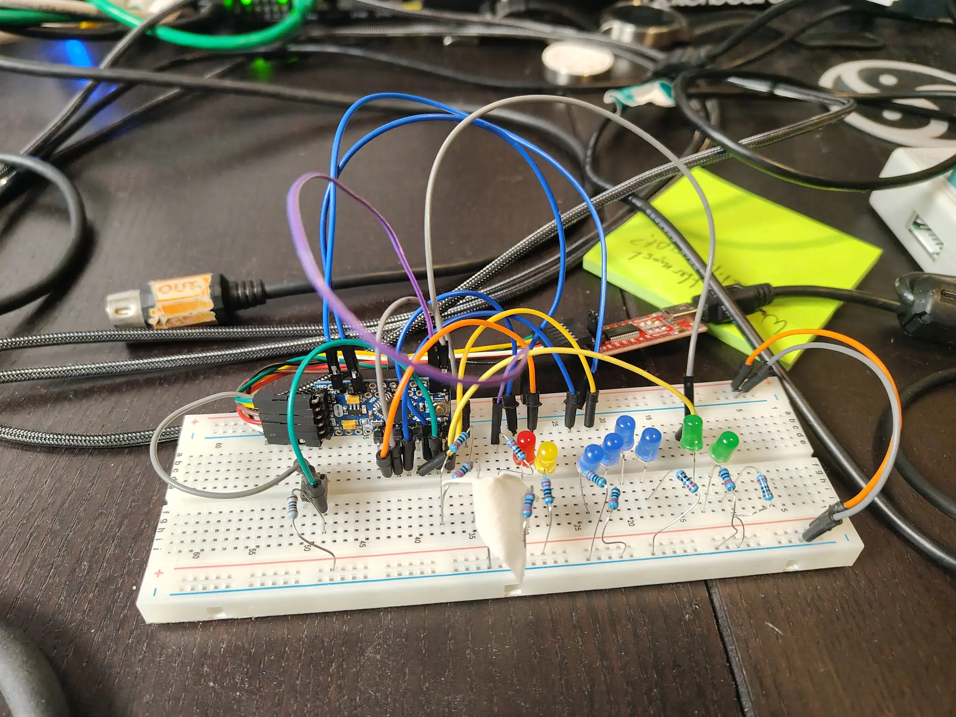
I made a rom switcher in the past. Now I’m using an Arduino to switch Kernal and Character rom. (Partly idea from Adrian)
Where the F* is my schematic. Ah here it is.
Above right picture:
Tactile button (emulates restore key)
Red led – reset
Yellow led – Exrom
Blue leds, Address lines select ROM part in 27512 EPROM
Green leds, Address lines select ROM part Character ROM
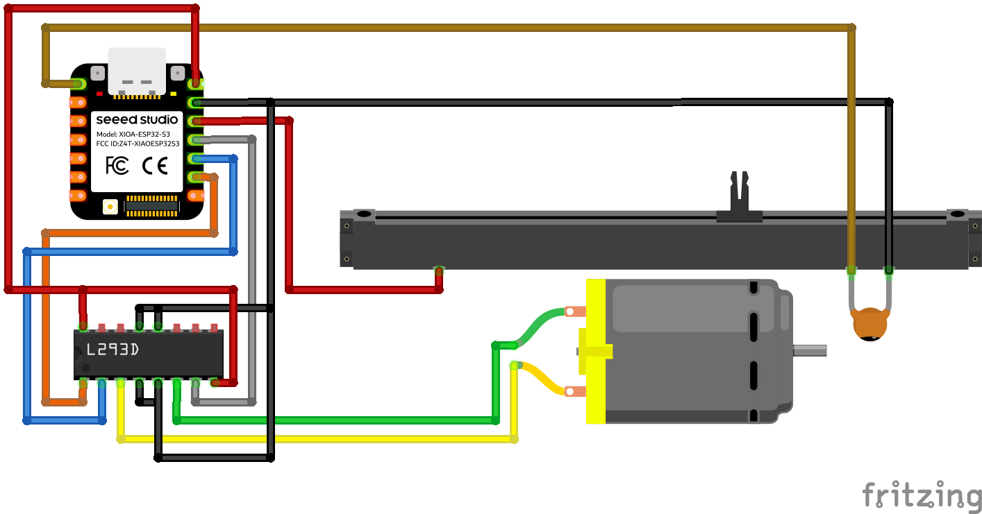
Motorized Fader Potentiometer
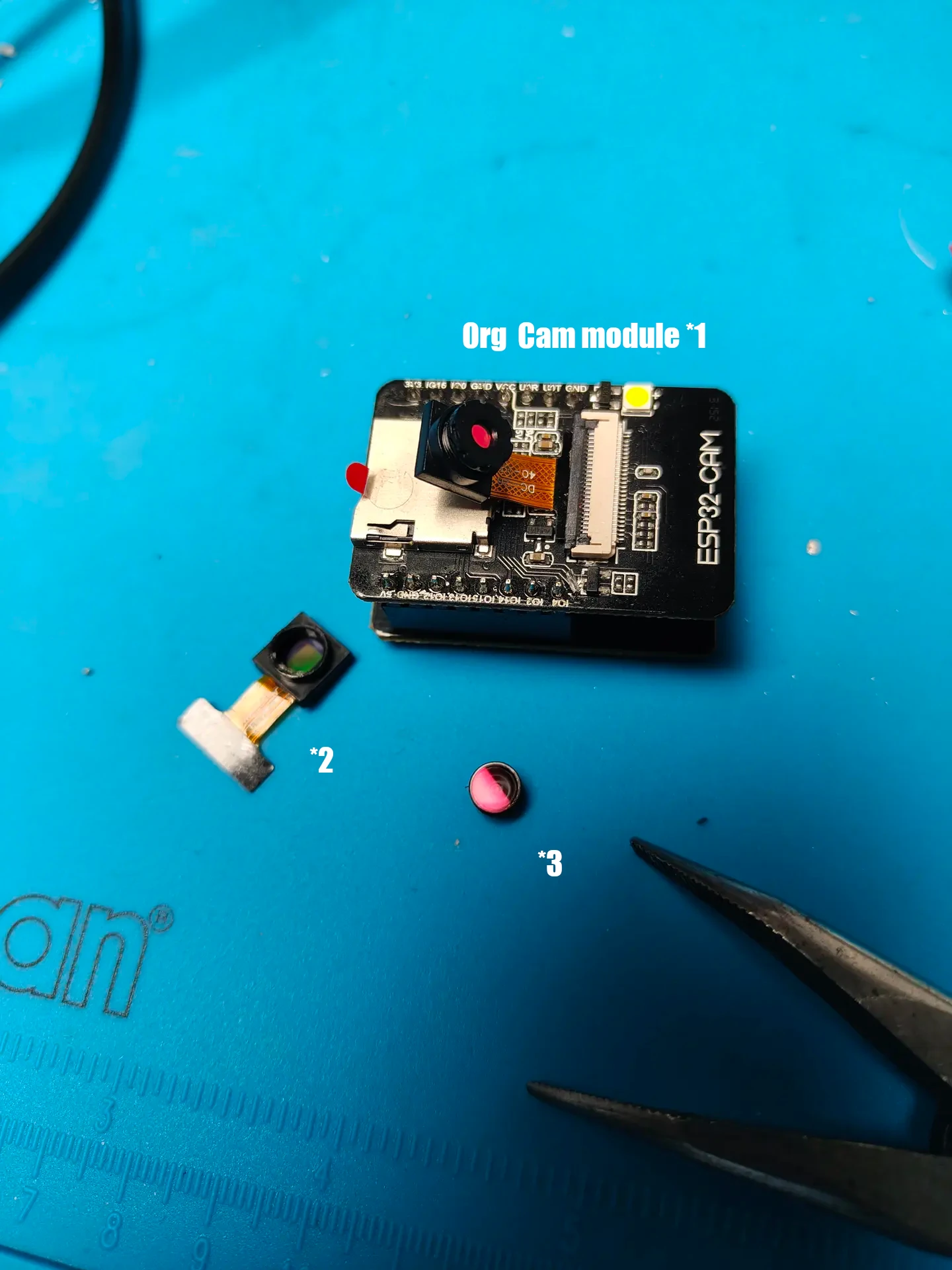
I don’t trust some B&B’s so I made a camera detector. (I always scan the wifi and Access Points) This one lets you know if there are IR enabled camera’s. (Night vision)
Picture 1:
1 = org camera module, IR filter is hard to remove. (See pink color)
2 = other module, IR filter is at bottom
3 = IR Filter, I removed this.
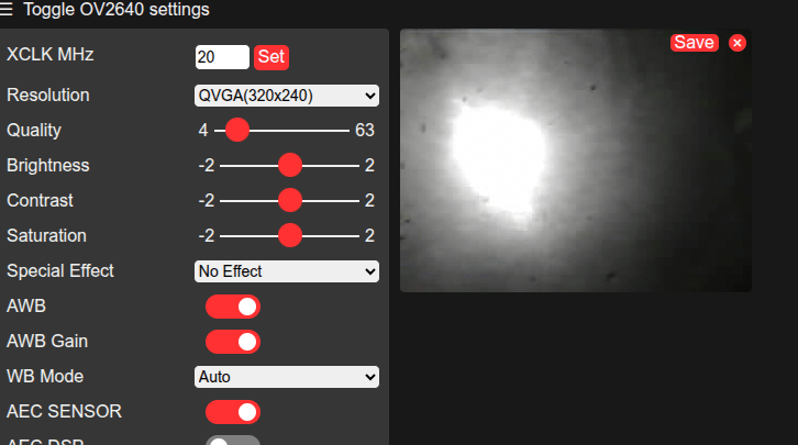
Picture 2:
IR light blast from a “hidden” camera. (I need to adjust focus of lens)
While I made this for my Commodore C64, it is applicable for many things.
It started with some cheap displays from Ali, and some leftover Wemos D1 from my Pressure Lab project.
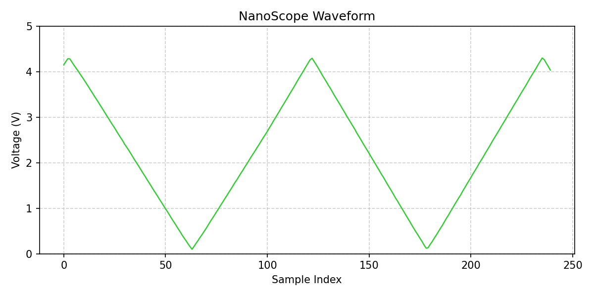
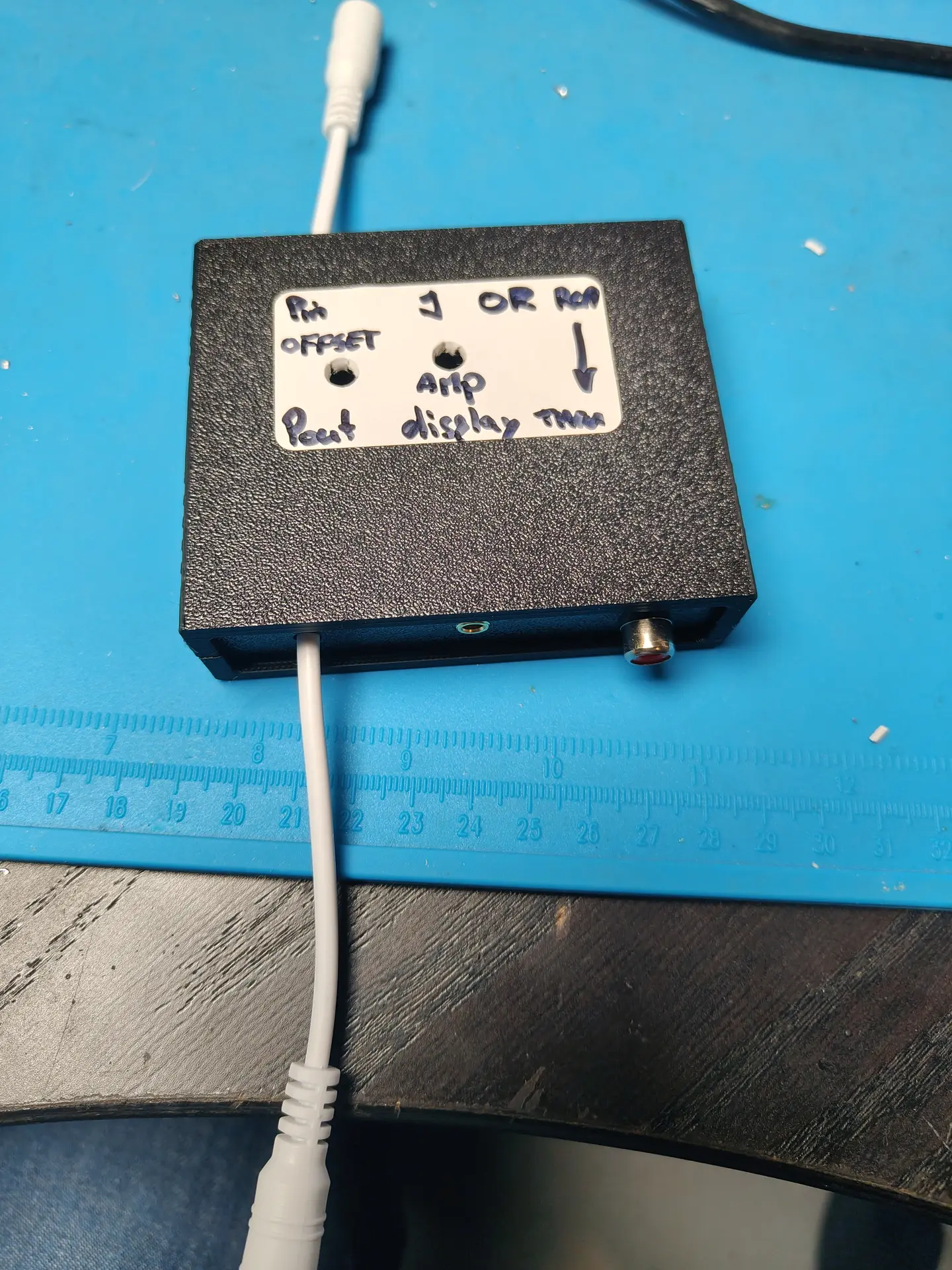
I Started measuring the audio output from sound devices and from my C64. I soon discovered that I needed some way to get the offset and amplification correct for the analogue input of a Wemos. (0-3v3)
So a little op-amp circuit was born, but not without some struggles. I forgot many things about amplifiers. It was one of the first school books I got rid of. (Sorry mister Rafaela)
After searching the internet and posting a question on Reddit I ended up with the following.
R1 and R2 are 100M. The potentiometer P1 allows me to set the offset. R3 is 1M C1 is 100nF to decouple the audio signal from the RCA.
R4 is 47K and C2 is 330nF (thanks tycho205) Cimportant=1/(2πfR2) where f is the lowest frequency of interest. In this case Cimportant should be about 330nF
LM324 is a quad amplifier, leftover from another project. Note, the SINGLE RAIL power.
P2 potentiometer is 2M (leftover) and gives me a variable amplifying opportunity.
A = Audio input
B = Setting the offset with P1
C = Setting the amplification
Below input signal (note negative values) above amplified signal with offset!
The displays are 3 Wemos controllers with a cheap I2C display. These are just fast enough to do FFT.
Analogue in is the output from the OP-amp offsetter ..
CODE
Needs cleaning up, and a better stabilizing routine.
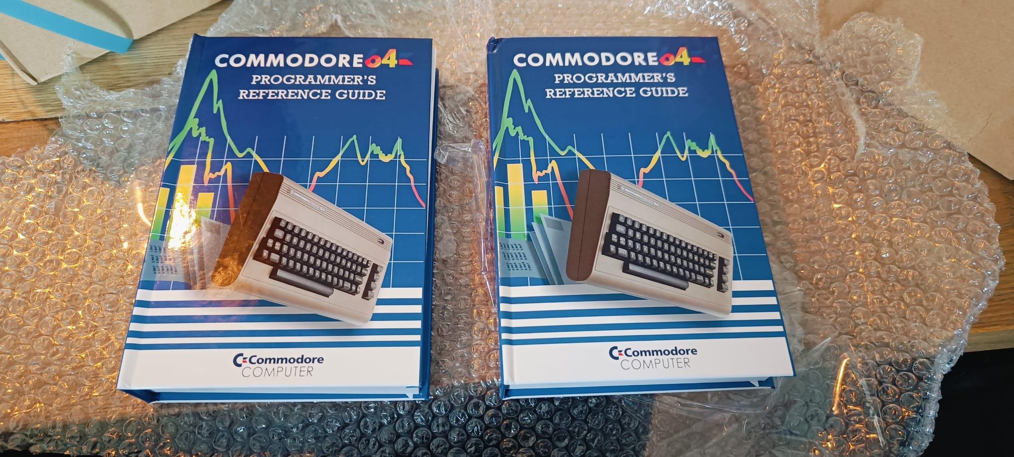
I’ve printed two books using the Lulu service. (One for Tyrone) When they arrived, I noticed some faults. Lucky Lulu will be printing them again for me.
The book has over 500 pages and has a nice hardcover.
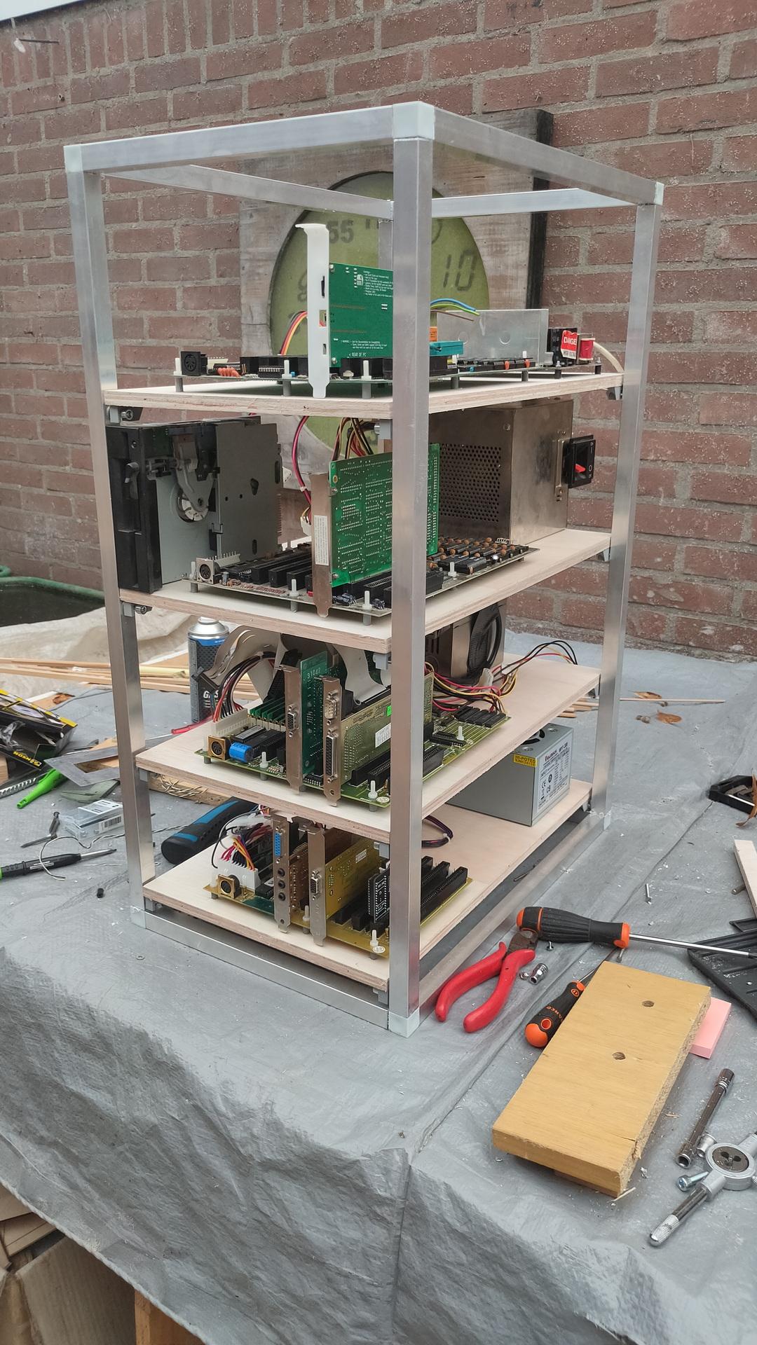
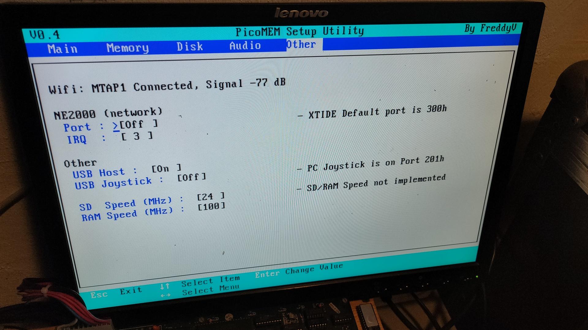
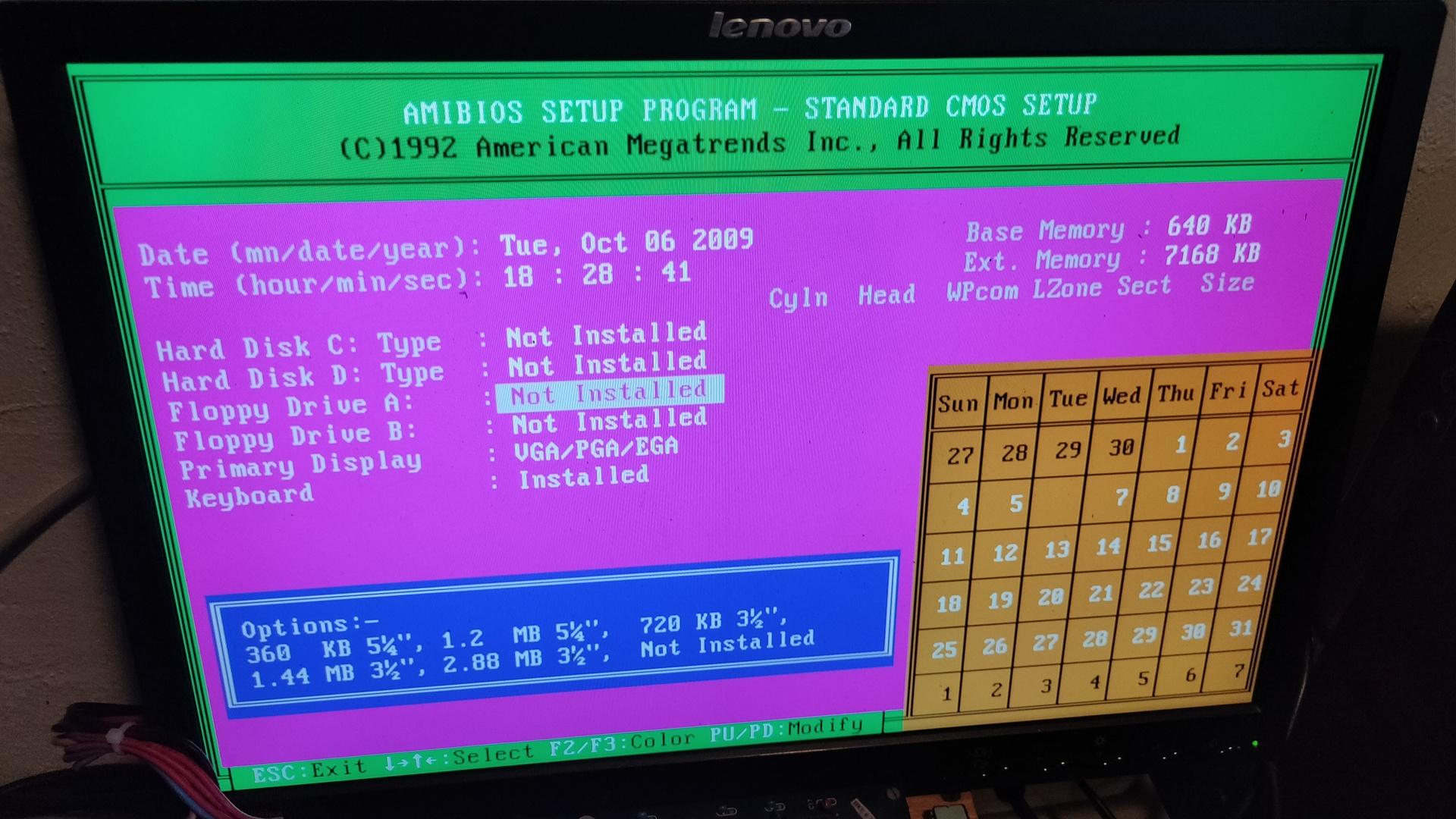
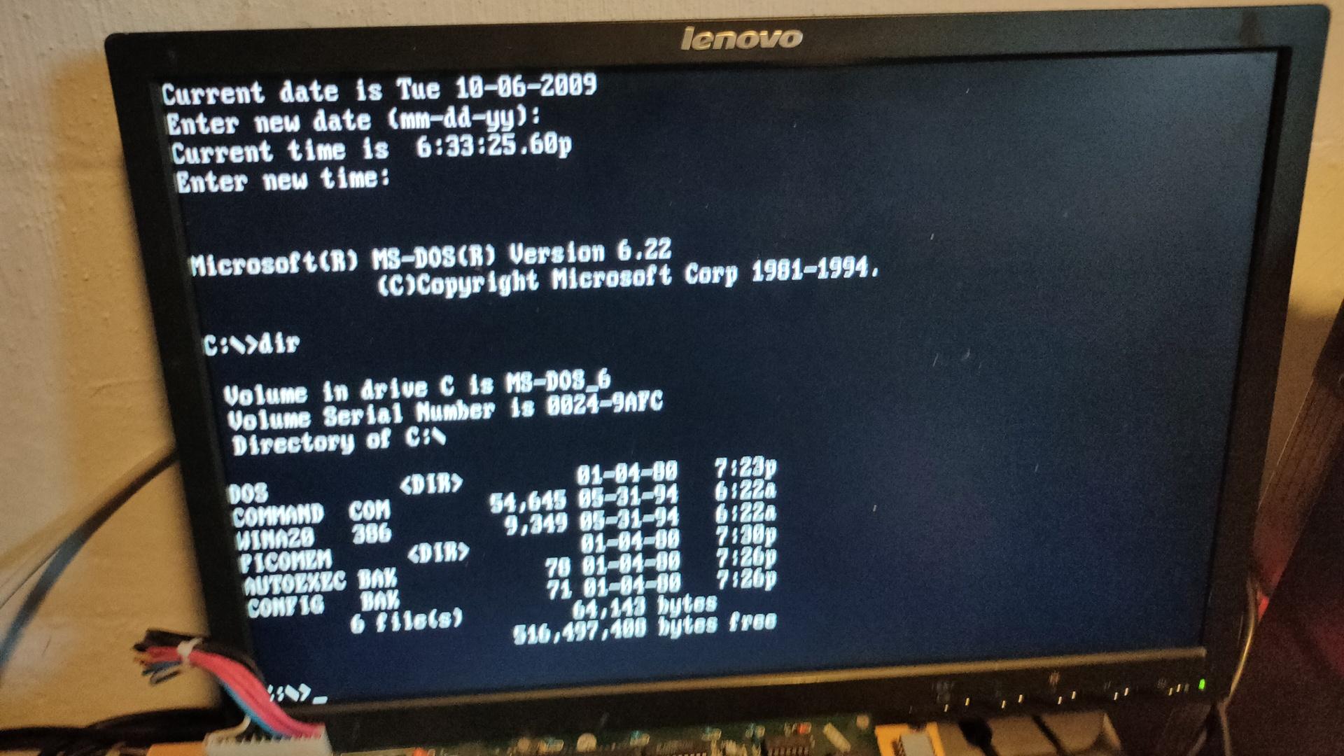
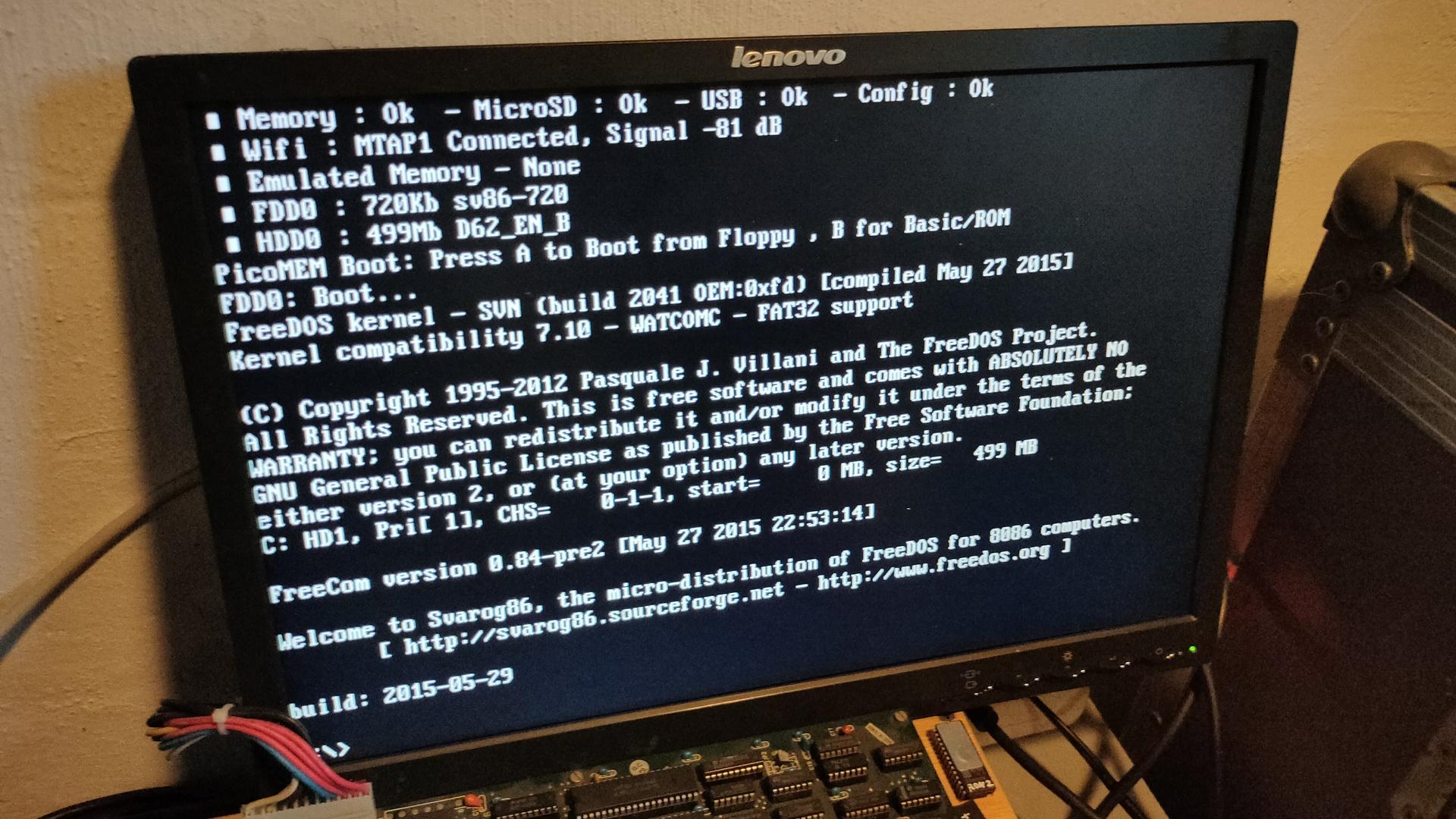
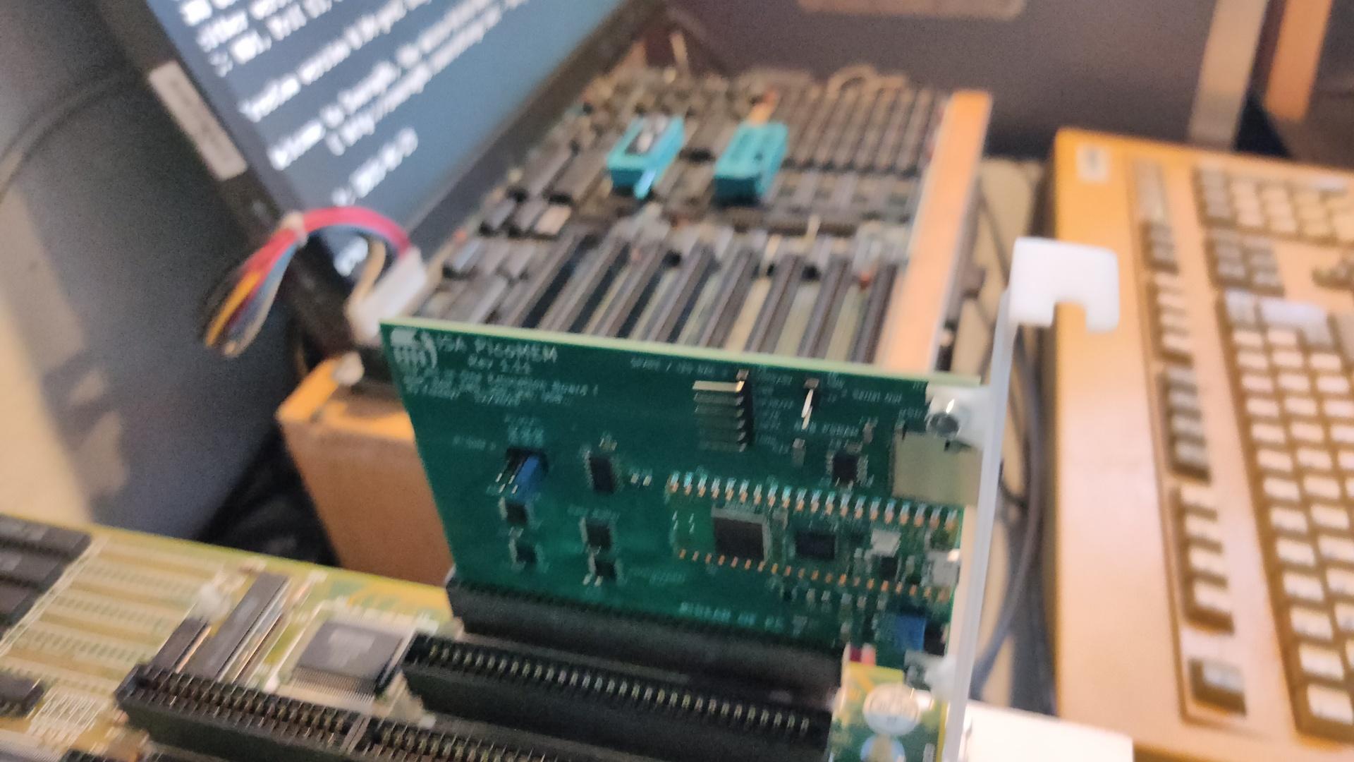
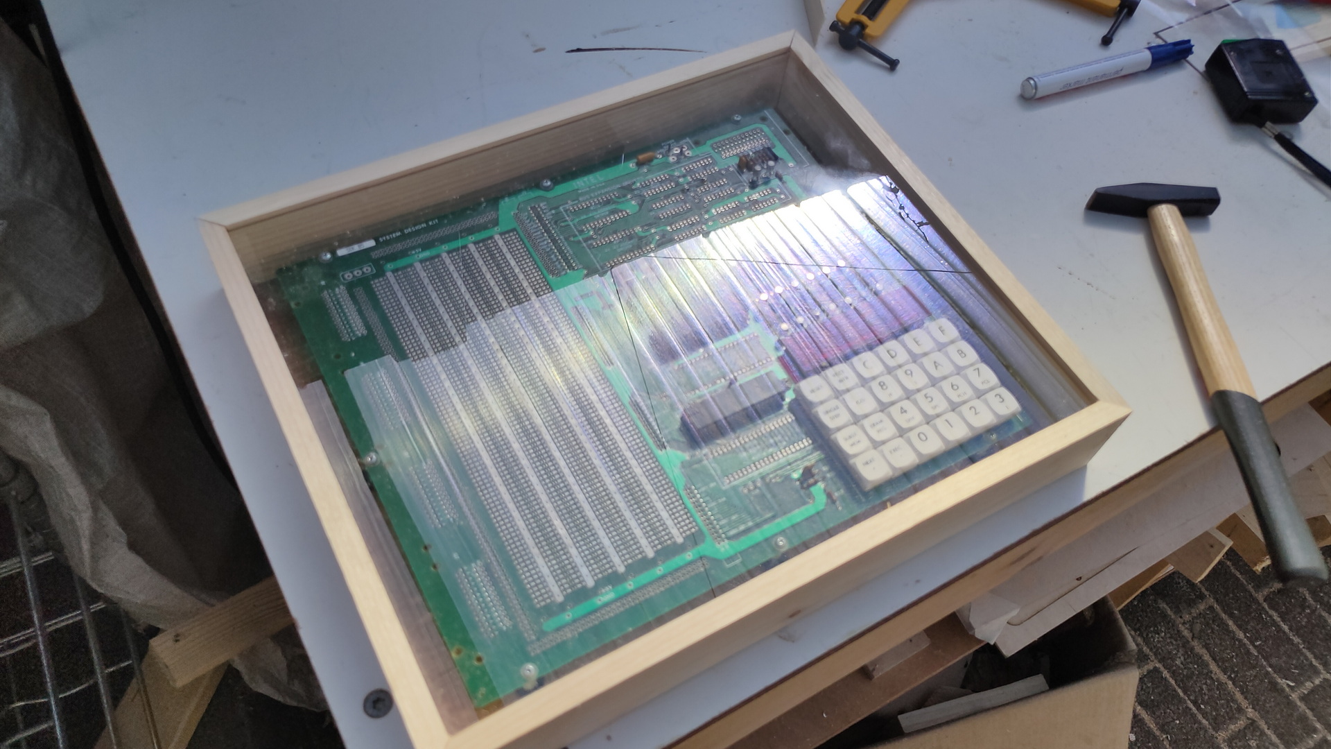
And I’ve been busy building a Mega Tower with 4 Motherboards. This will have a superb processing power! .. not. It houses some old motherboards for hardcore machine coding on real old hardware.
From top to bottom: 8088, 8086, 80386, 80484
Todo:
Rework on the cables
3D print an information plaque on the front of each board
Add a control panel on each board
Maybe some dust cover would be nice
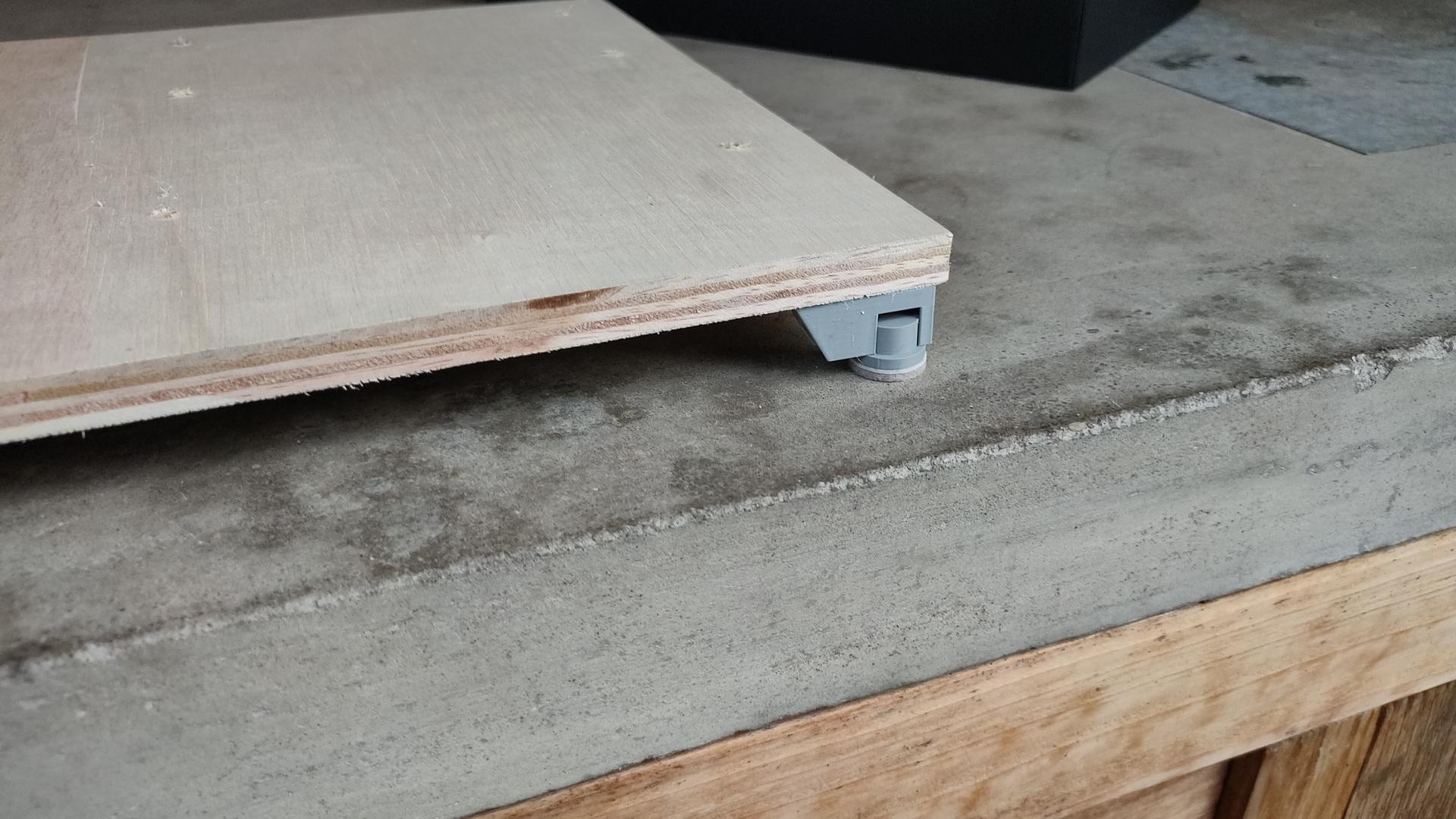
I can remove the boards, and place them on a table. I’ve made some custom feet for them. Twist and lock by my own design.
Padded feet
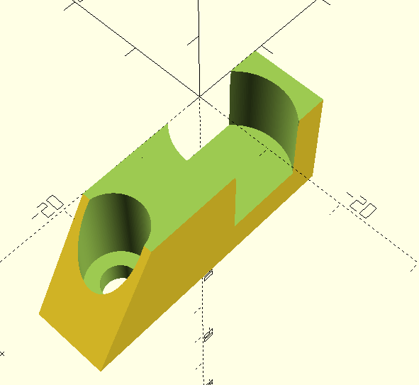
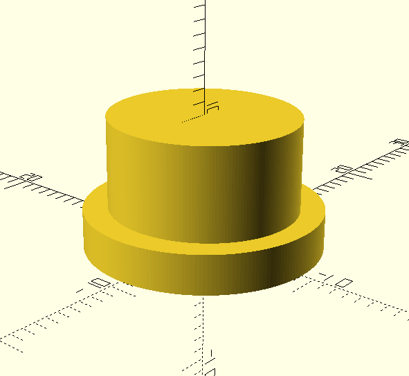
The openscad files:
The locking is done by making the cylinder slightly oval by 0.5mm
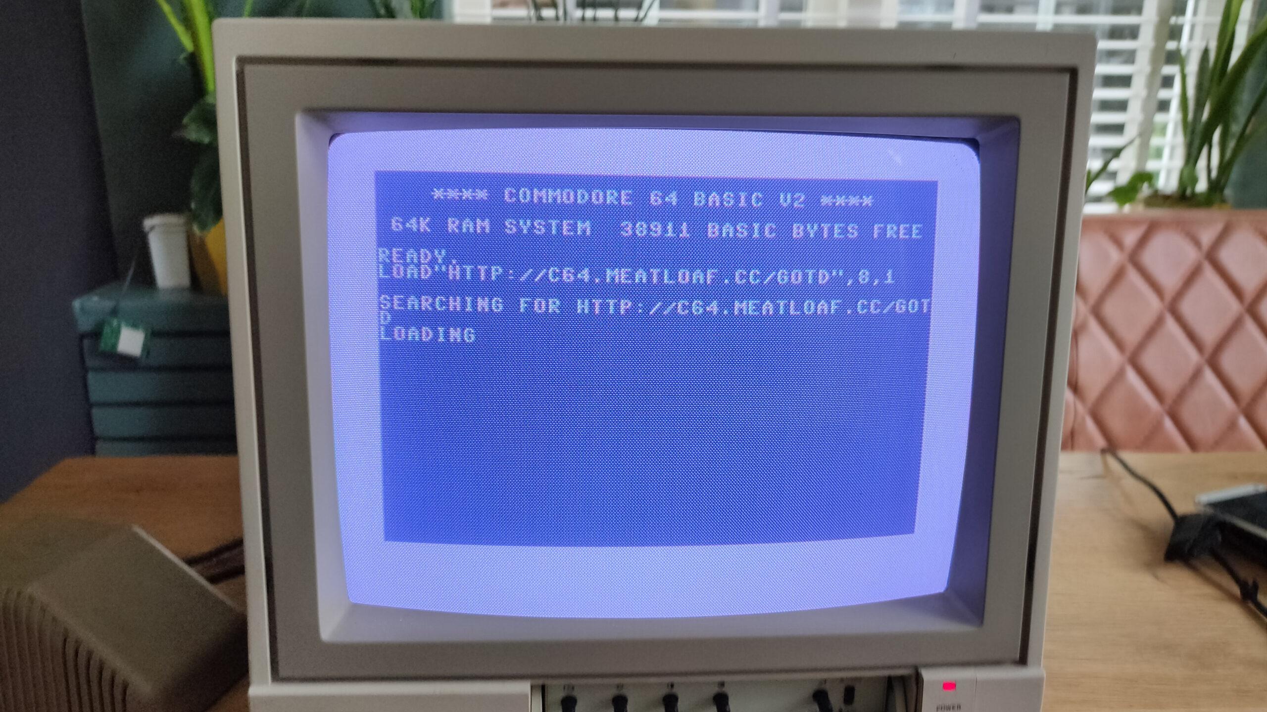
Emulates a floppy drive: Meatloaf plugs into the Commodore 64’s IEC serial port and acts like a virtual floppy drive. This allows you to load software and data stored on its internal flash memory, sd card, or stream it via WiFi using various protocols from servers all over the world.
Supports multiple virtual drives: Unlike a single floppy drive, Meatloaf can be configured to emulate up to 26 virtual drives (IDs 4-30). Each virtual drive can have a different disk image loaded, essentially offering the equivalent of having thousands of floppies connected to your C64.
Supports additional virtual device types: Printers, a network interface, and more.
Connects to the internet: Meatloaf also functions as a WiFi modem, enabling your Commodore 64 to connect to Telnet BBS (bulletin board systems) for communication and sharing information.
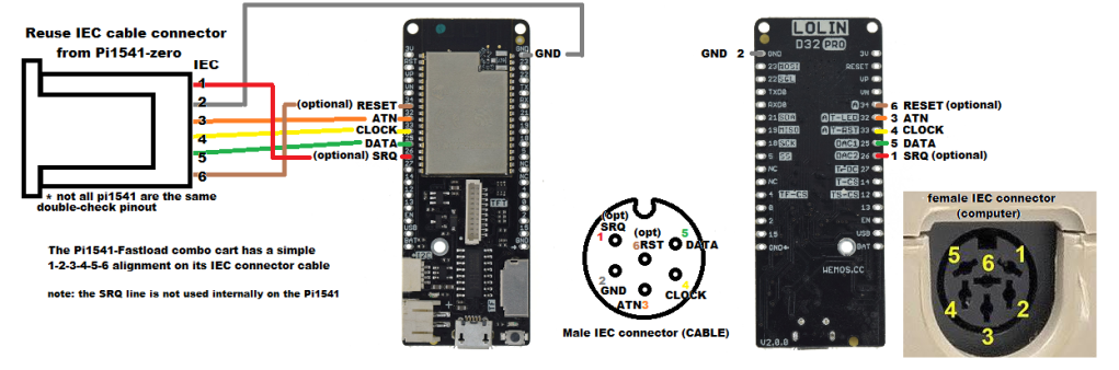
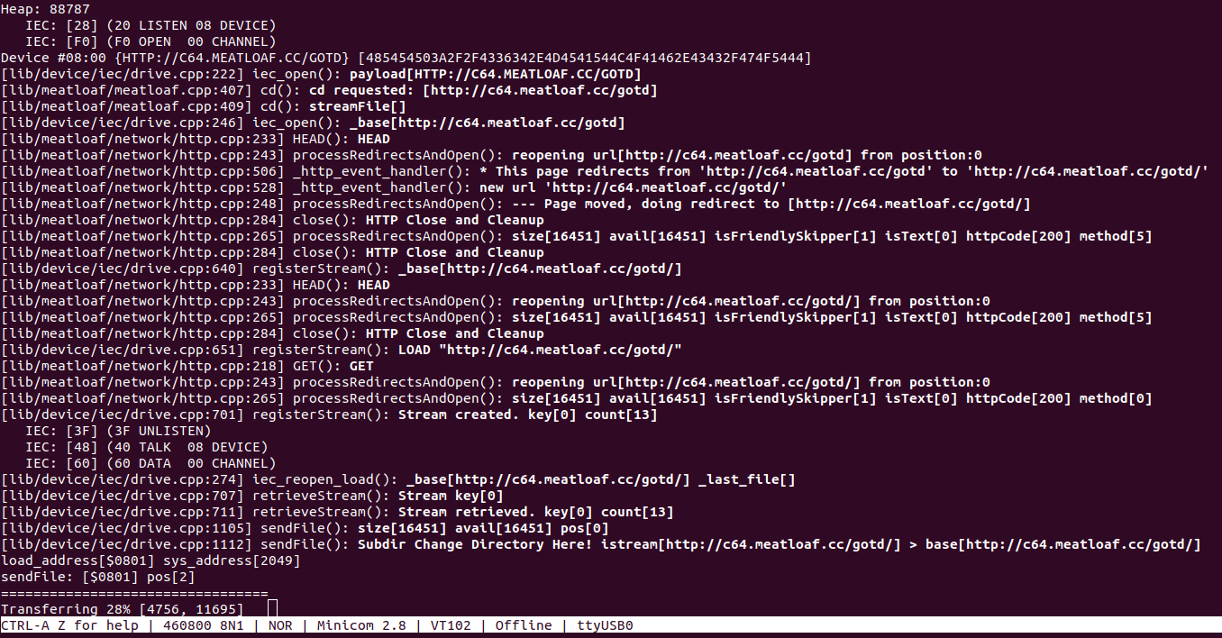
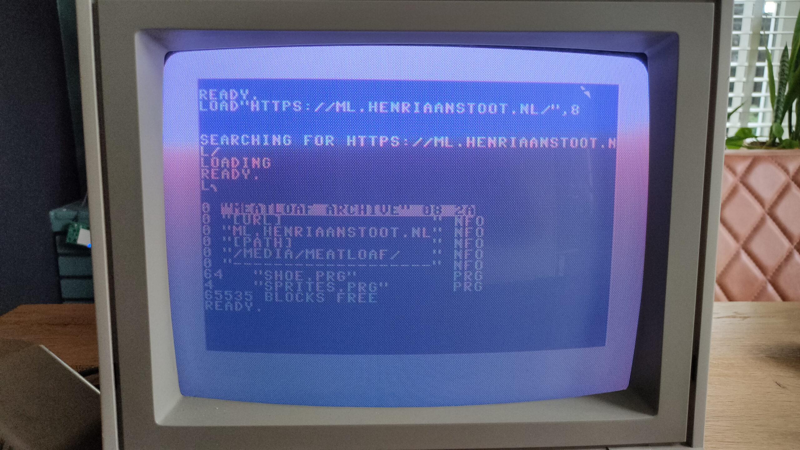
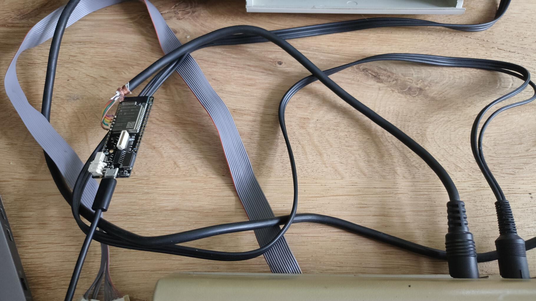
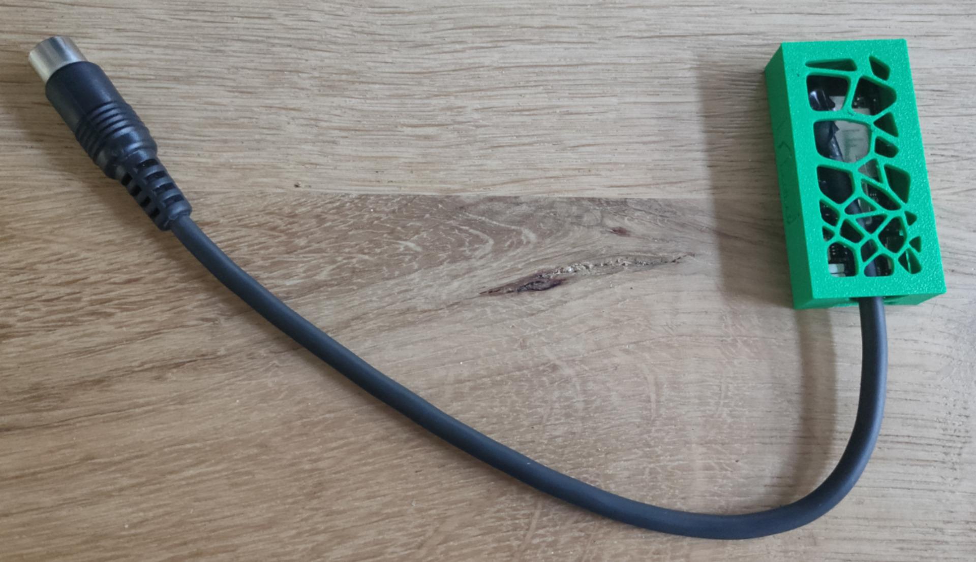
load from urldebug outputmy own repo testOnly a Lolin D32 and a cable with din connector.
I’ve been busy programming Python and NodeRed for a client. But these are the things I’ve done in the last days.
C64 Assembly: Breaking borders, using sprites and multicolor font intro.
It does not look impressive, but I’ve learned a lot. Found a new way (for me) to open borders and change border colours on predefined raster lines. Sources will be posted.
KiCad tutorial, posted on YT also because I could not find many resources about the subject online. Maybe it’s helpful
Video editing using Kdenlive.
Edit: Even faster, use Netlabels, no need to join pins. Press L (uppercase) select pin 1, name 1. Press and hold insert until all pins named. Copy paste socket 5 times and goto your PCB tab.
This movie is about creating a backplane for a 6502 SBC I’m building. It is real-time and below 4 minutes.
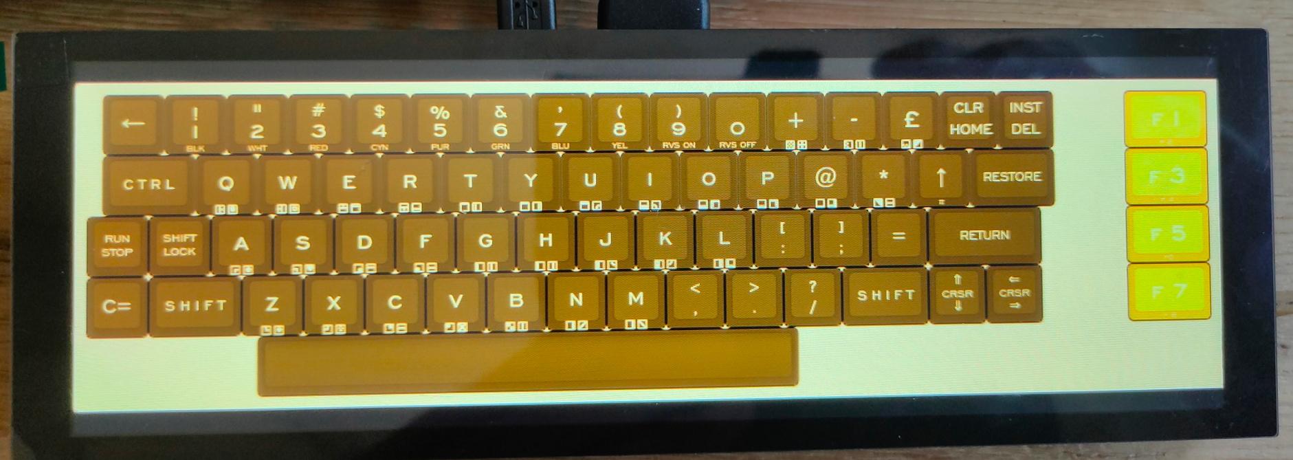
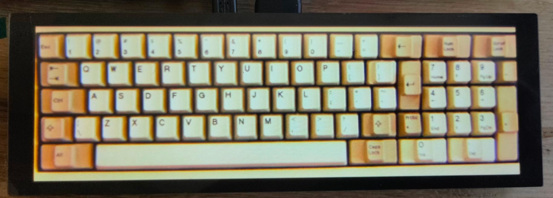
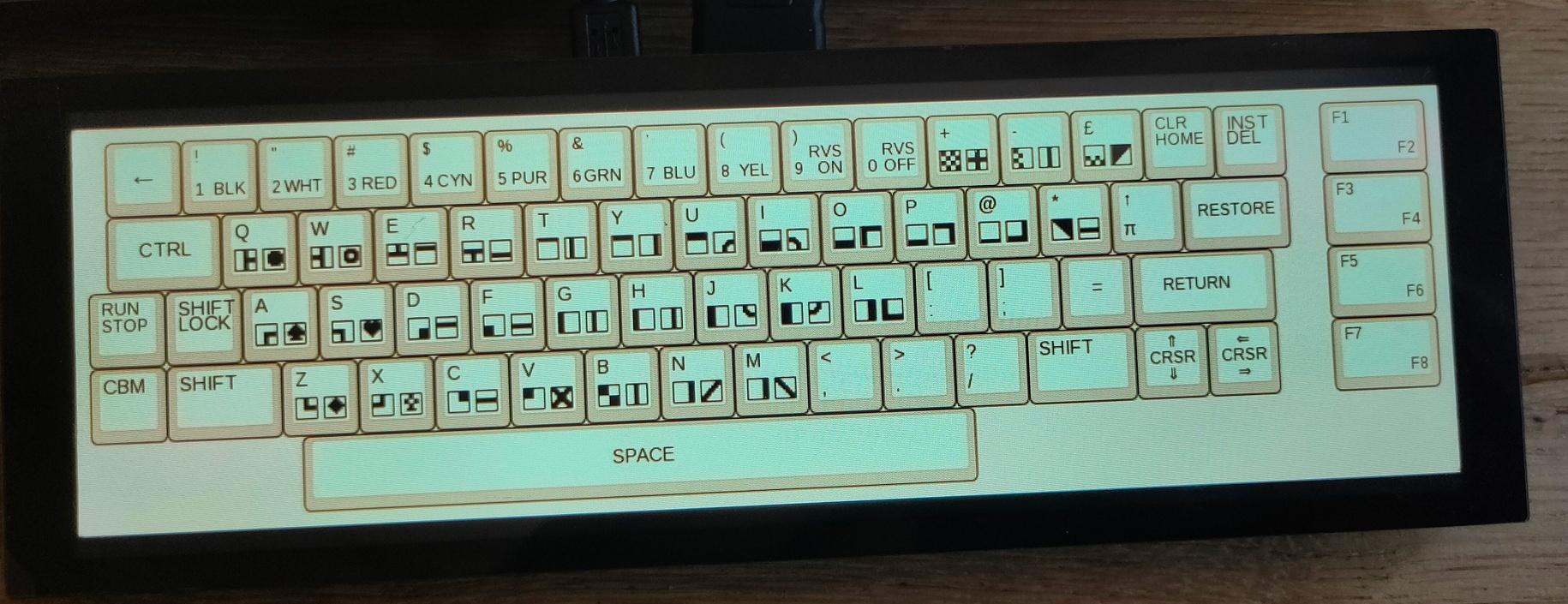
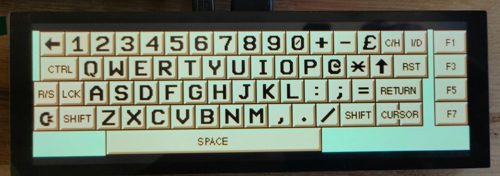
Multi Keyboard
My small multitouch screen came in. This is for my previously mentioned multi-computer case.
It is going to show multiple keyboard layouts for different systems. (See previous posts about this)
Waveshare display, Raspberry Zero as HID device, using USB and pin emulated keyboards. (c64 matrix, AT (DIN) keyboard, ps2 keyboard)
Some example screens
Vic-20
Photo-realistic
Petscii C64
Another C64
I’m also going to make a layout like the keyboards on my 8085
"If something is worth doing, it's worth overdoing."