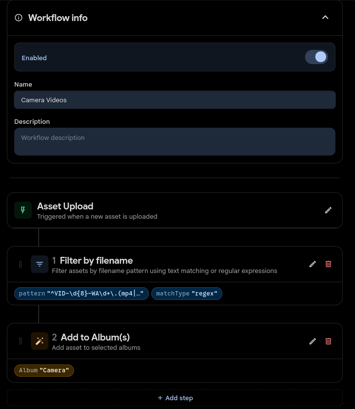
UPDATE 20260729 : There are EXIF filters in workflows now!
Put your media in the correct directories using workflows.
Below the regex for a Samsung phone
Image
^\d{8}_\d{6}\.(jpg|jpeg|heic|png)$

Video
^\d{8}_\d{6}\.(mp4|mov|mkv)$

WhatsApp Image
^IMG-\d{8}-WA\d+\.(jpg|jpeg|png|webp)$

WhatsApp Video
^VID-\d{8}-WA\d+\.(mp4|3gp)$

Signal Image
^(signal-|Signal-).*\.(jpg|jpeg|png|webp)$

Signal Video
^(signal-|Signal-).*\.(mp4|mov)$
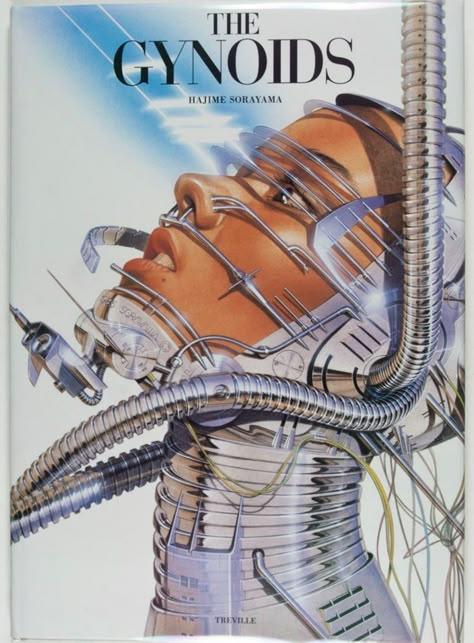
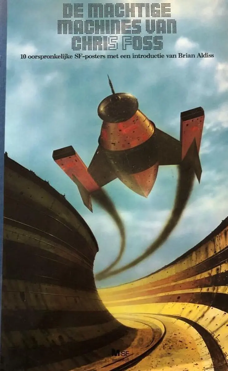
While browsing the Internet, something popped up. An image of a spaceship, and I instantly remembered where I’ve seen it before.
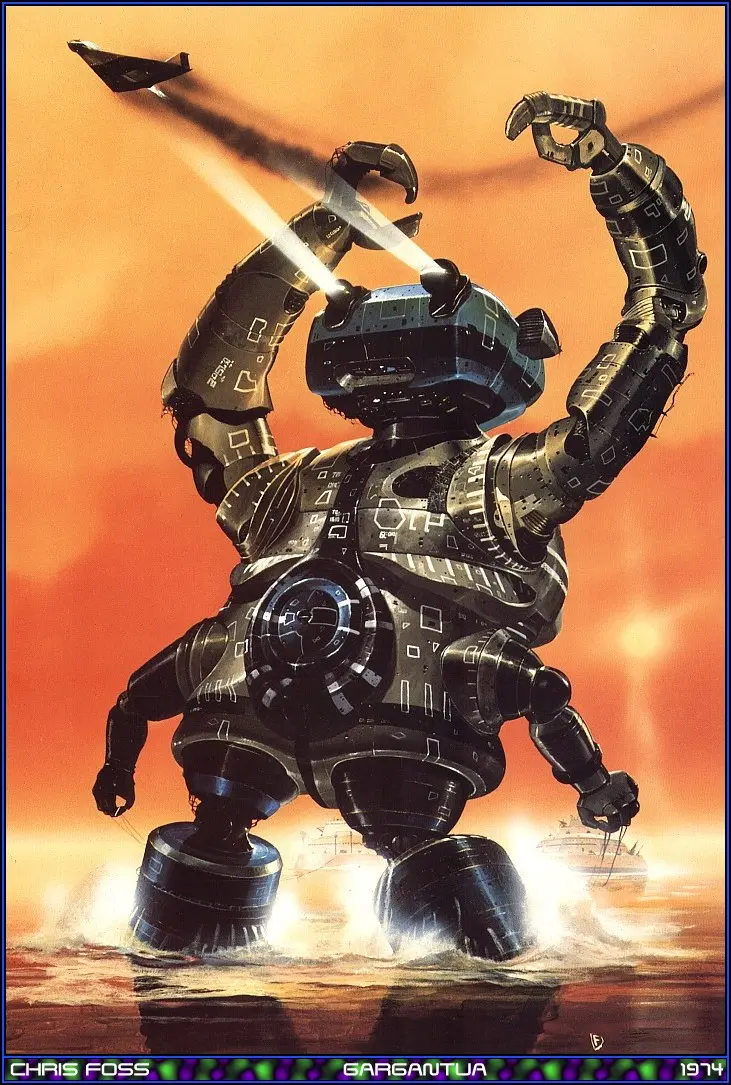
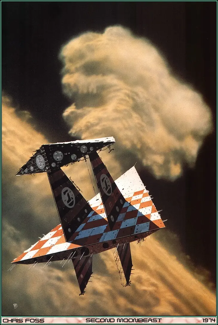
When I was a teenager I got hold of a book from Chris Foss, it was a large book with only around 8-10 pages.
But I loved the images. (I shamefully admit, that I traded the book for something else a long time ago) 46x29cm printed in 1977 (See more at end of post)
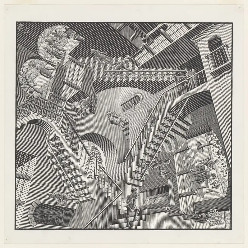
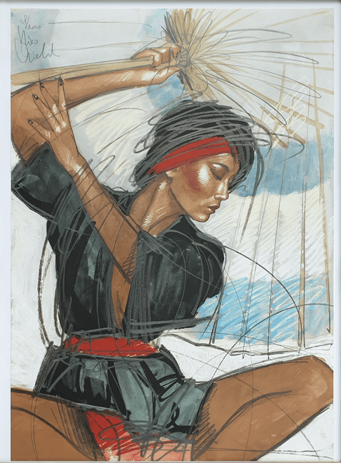
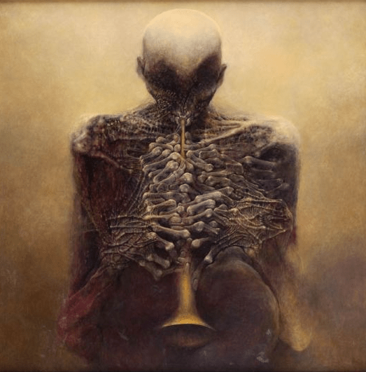
At that time I had several artists that really peaked my interest in graphical arts. I still love to paint and draw.
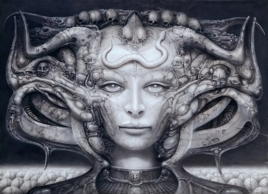
A Swiss artist best known for his airbrushed images that blended human physiques with machines, an art style known as “biomechanical”. He designed for several movies : Alien, Species and Dune
I listen to all kinds of music, metal till classical.
Mostly Celtic/Irish/Scottish/Bagpipes. But i’ve listen to below also.
In the summer I often listen to Cuban/Latin music when outside.
Most of what I listen too, has to have some technical or difficult hints to get me interested.
Master of puppets metallica
“La campanella” is a revision of an earlier version from 1838, the Études d’exécution transcendante d’après Paganini, S. 140. Its melody comes from the final movement of Niccolò Paganini‘s Violin Concerto No. 2 in B minor (yeah as mentioned in another post, I am a Paganini fan)
Very nice technique on Guzheng using two slides, key change and vibrato.
Some classic composers ( When I’m in the mood, these will be played )
First time listening to classical music, was in 6 grade (8 nowadays). The Four Seasons by Vivaldi, another great composer