At the WHY2025 hackers event, we used bigred’s antenna pole to make a huge sign using leds.
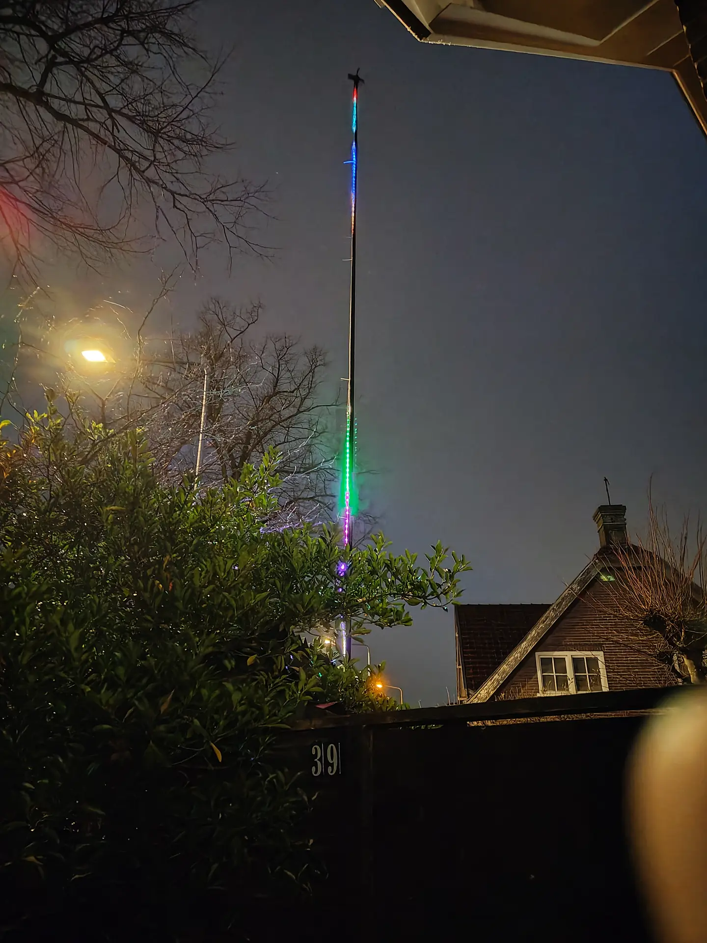
It gave me the idea to make a pole which displays digital “fireworks” using leds.
Fireworks are becoming illegal the next year in the Netherlands, I think.
So why not going digital?
12 Meter pole, 300 Leds.
There is a QR code and a website link mentioned on a page at the gate.
10 presets to select via a website.
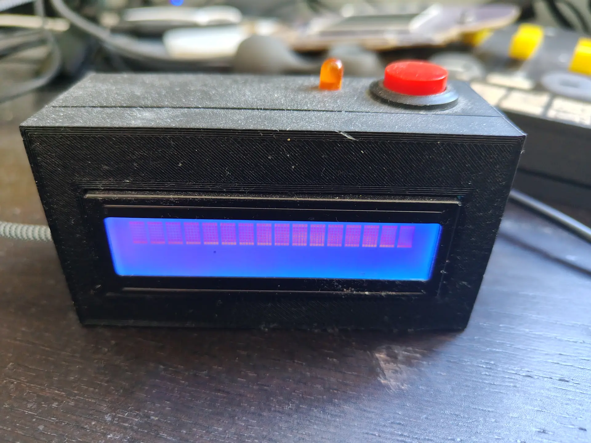
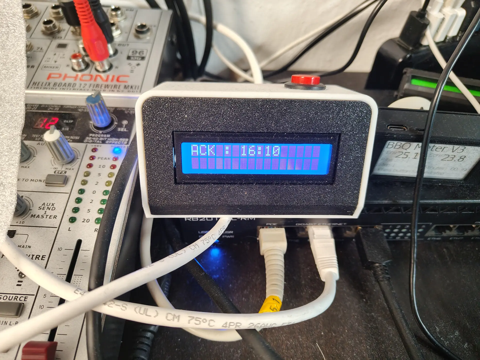
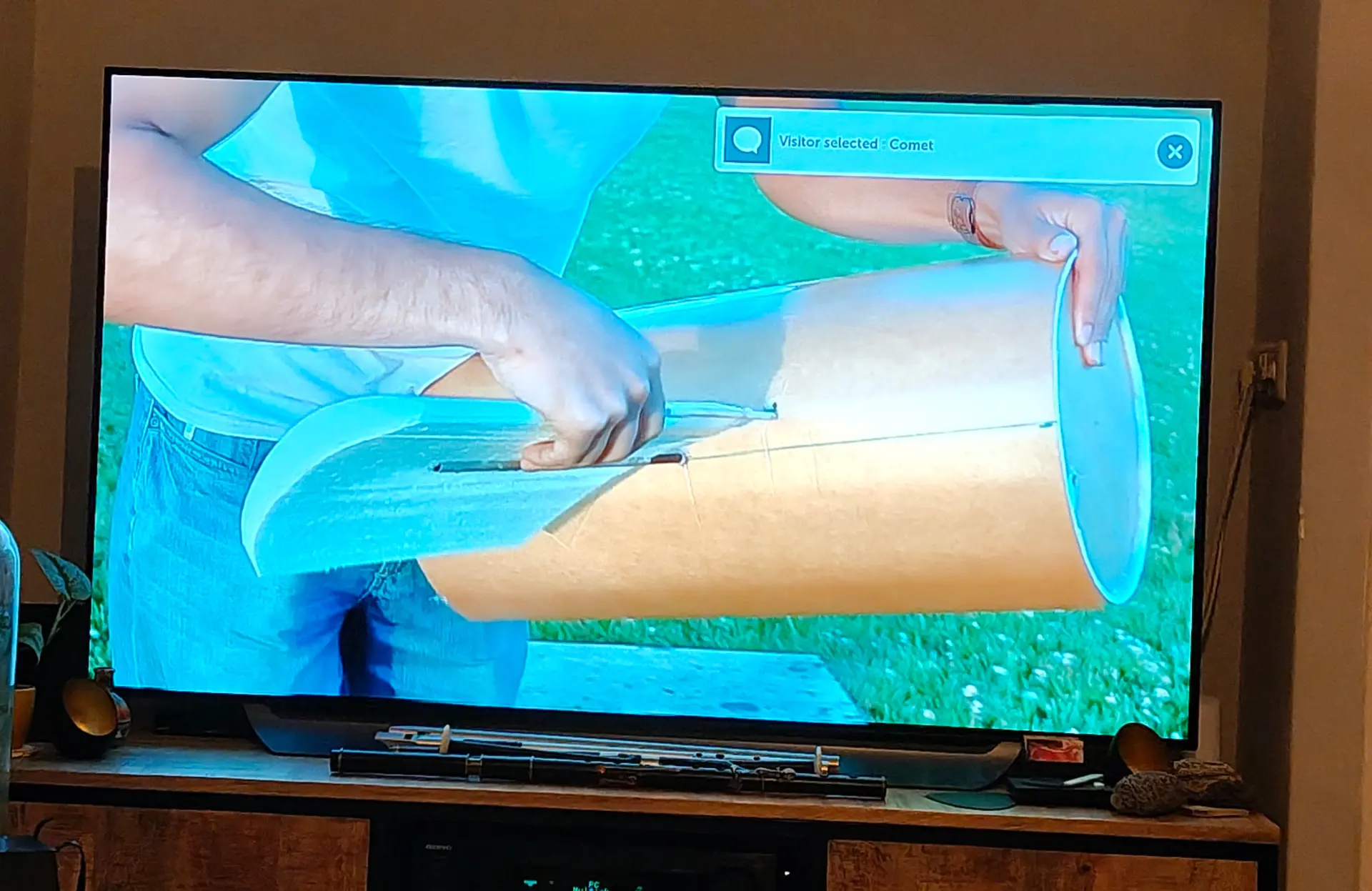
Notification on my TV
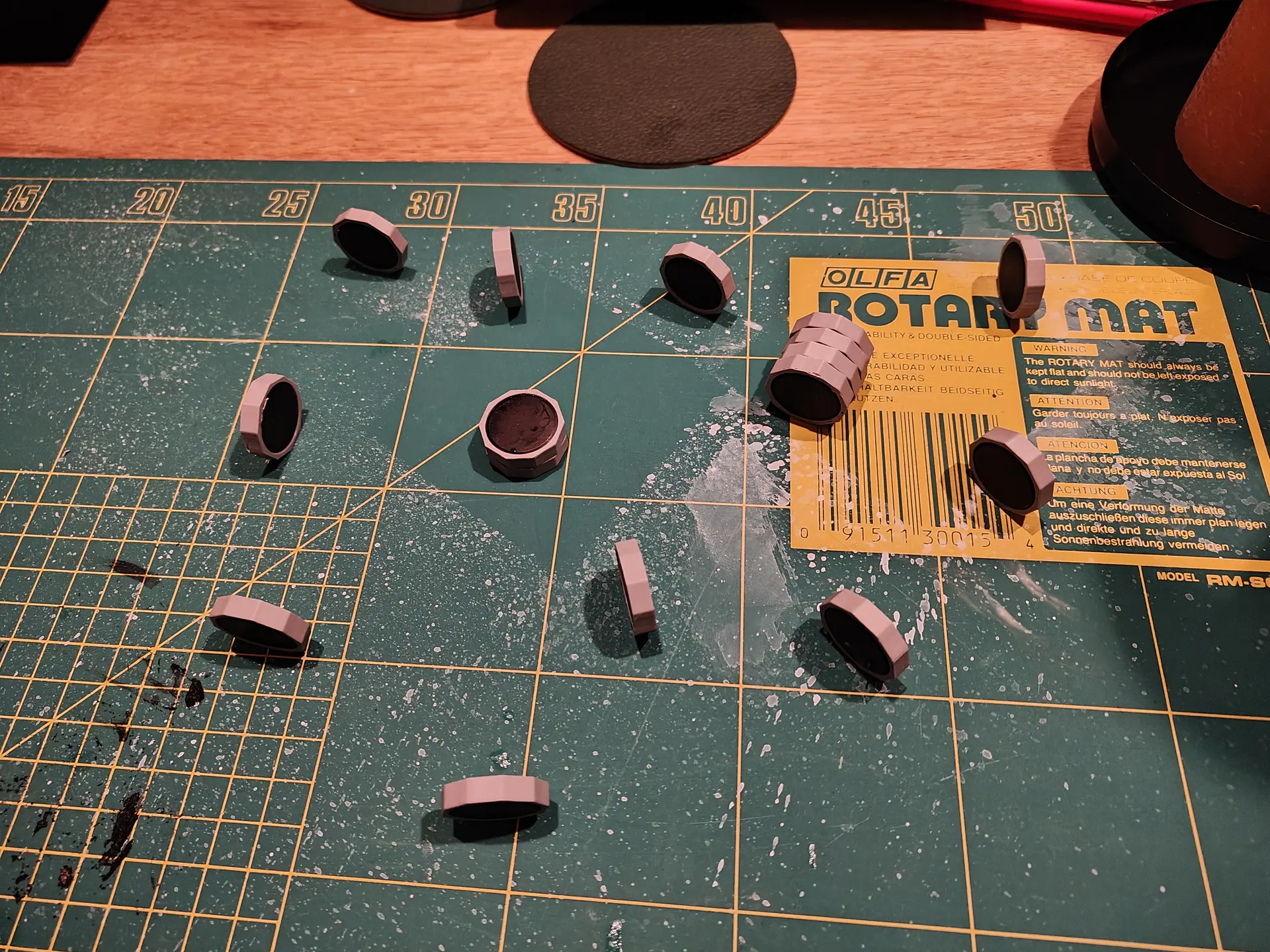
While waiting for the first visitor I made a magnetic game.
Using a bunch of magnets, and 3D printed hexagon rings.
Two players try to place magnets in a small area without moving the others. If magnets slam together, you have more pieces to place.
(Below, last player has to take those 6 pieces)
CODE for website index.html
<html>
<head>
<meta name="viewport" content="width=device-width, initial-scale=1">
<title>WLED Mast</title>

<style>
body {
    background: #111;
    color: #fff;
    font-family: Arial;
    margin: 0;
    padding: 20px;
    text-align: center;
}
.grid {
    display: grid;
    grid-template-columns: repeat(2, 1fr);
    gap: 18px;
}
button {
    padding: 25px;
    font-size: 22px;
    border-radius: 20px;
    border: none;
    background: #333;
    color: #fff;
    font-weight: bold;
}
button:active {
    background: #555;
}
</style>
</head>

<body>

<h1>WLED Mast</h1>

<div class="grid">
    <button onclick="run('b1')">off</button>
    <button onclick="run('b2')">fireworks</button>
    <button onclick="run('b3')">sound<BR>reactive</button>
    <button onclick="run('b4')">bounch-balls</button>
    <button onclick="run('b5')">fire</button>
    <button onclick="run('b6')">juggle</button>
    <button onclick="run('b7')">swing</button>
    <button onclick="run('b8')">sparkle</button>
    <button onclick="run('b9')">popcorn</button>
    <button onclick="run('b10')">comet</button>
</div>

<script>
const API_KEY = "misuse-prevent";

function run(action) {
    fetch(`/action.php?action=${action}&key=${API_KEY}`)
        .then(r => r.json())
        .then(j => console.log(j))
        .catch(err => alert("Error"));
}
</script>

</body>
</html>
CODE for Wled API
<?php

$public_api_key = "misuse-prevent";
if (!isset($_GET['key']) || $_GET['key'] !== $public_api_key) {
    http_response_code(401);
    die("Unauthorized");
}

$action = $_GET['action'] ?? null;

// Map 10 buttons → WLED preset numbers
$allowed_actions = [
    "b1"  => 19,
    "b2"  => 22,
    "b3"  => 23,
    "b4"  => 20,
    "b5"  => 21,
    "b6"  => 3,
    "b7"  => 8,
    "b8"  => 2,
    "b9"  => 4,
    "b10" => 14
];

if (!$action || !isset($allowed_actions[$action])) {
    http_response_code(400);
    die("Invalid action");
}

$preset = $allowed_actions[$action];

// ---- WLED IP address ----
$wled_ip = "http://WLEDDEVICEIP";   // <-- CHANGE THIS

// API endpoint
$url = $wled_ip . "/win&PL=" . $preset;

// Call WLED directly
$ch = curl_init($url);
curl_setopt($ch, CURLOPT_RETURNTRANSFER, true);
curl_setopt($ch, CURLOPT_CONNECTTIMEOUT, 2);
curl_setopt($ch, CURLOPT_TIMEOUT, 2);

$response = curl_exec($ch);
$error = curl_error($ch);
curl_close($ch);

header("Content-Type: application/json");

if ($error) {
    echo json_encode(["ok" => false, "error" => $error]);
} else {
    echo json_encode(["ok" => true, "preset" => $preset]);
}