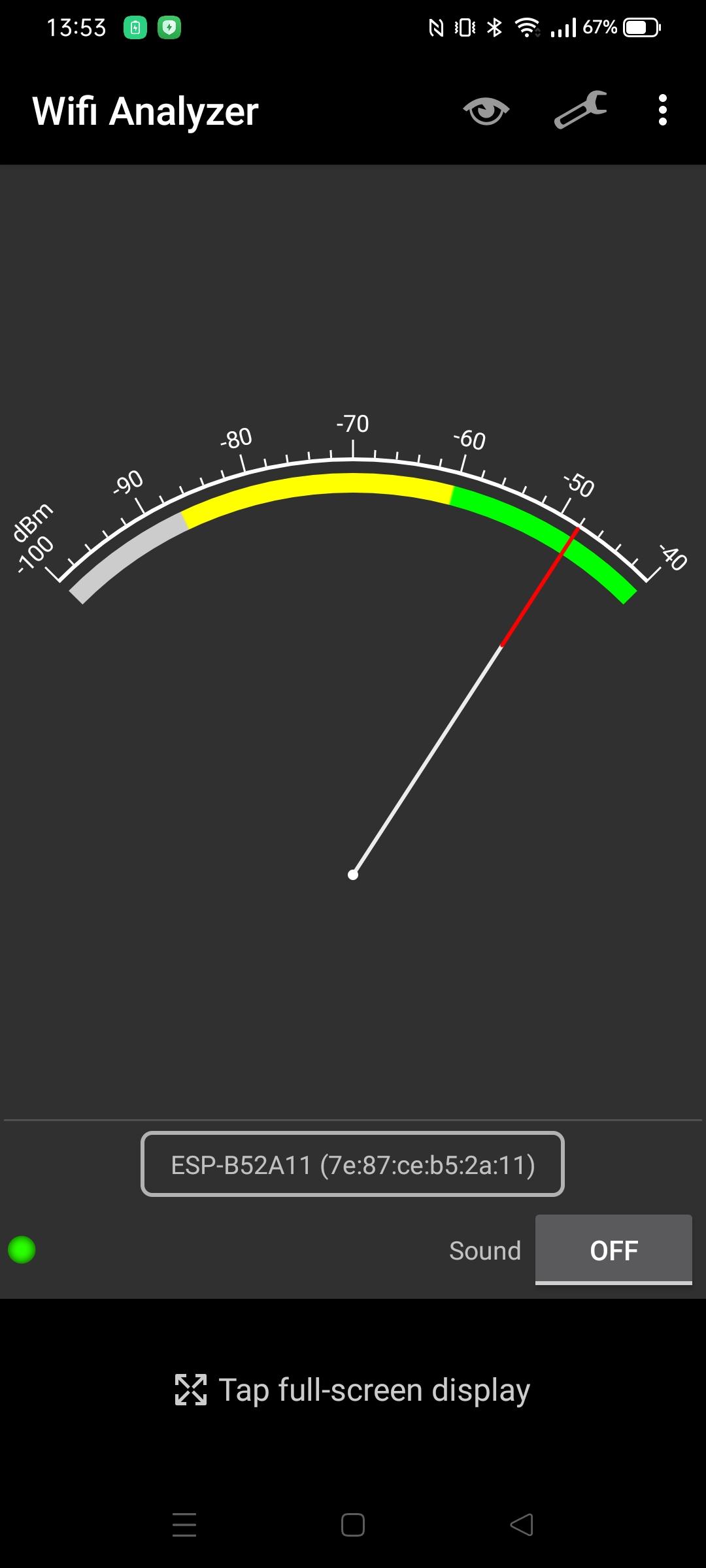
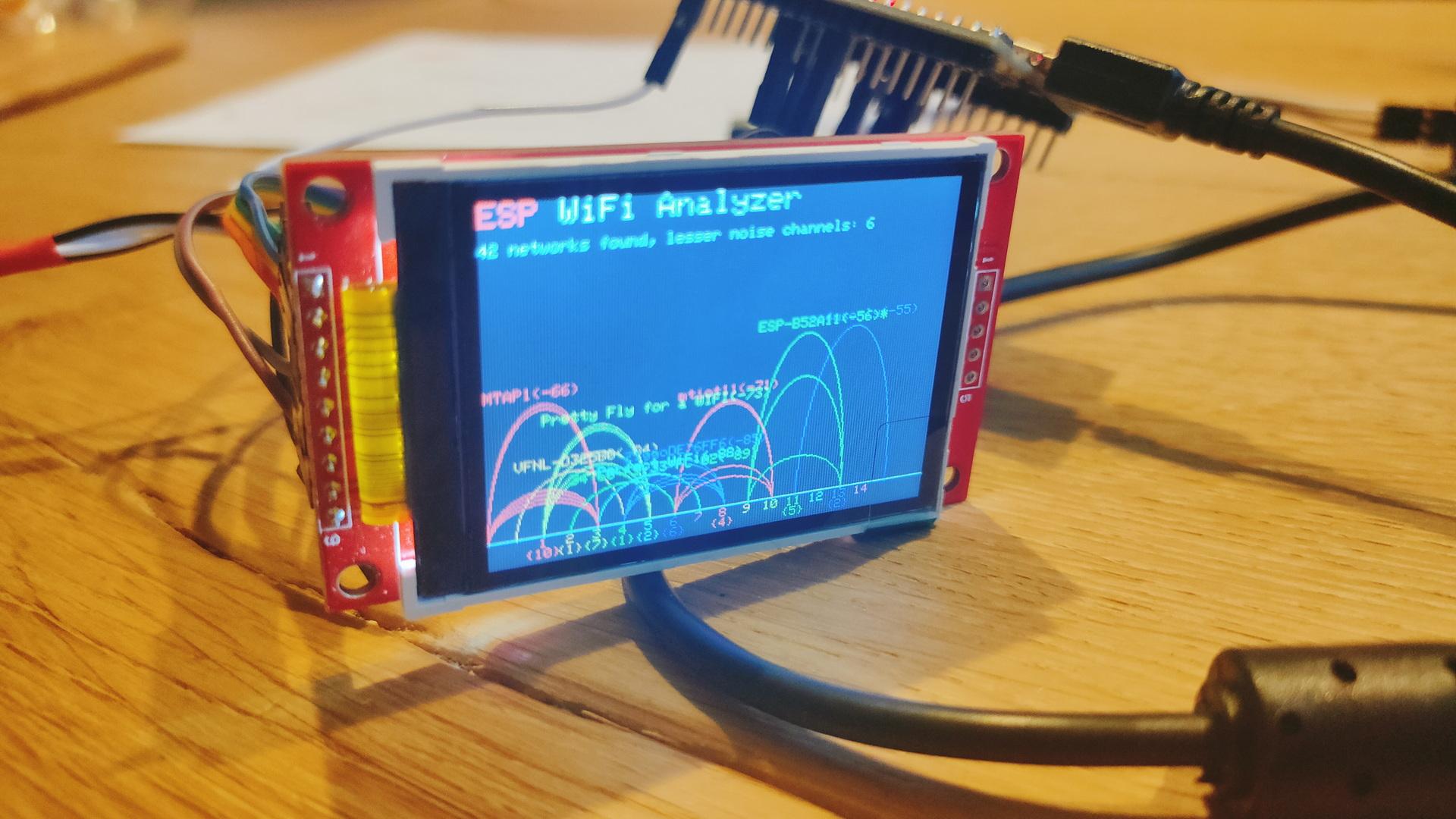
Its SSID started with ESP. So I probably am the one responsible for its existence. I’ve got a sh*tload of ESPs/NodeMCUs/8266 turned on 24-7.
Using a Wifi analizer I could narrow it down to my livingroom. Checked all devices, and they are all connected to my AccessPoint. (So no fallback AP mode)
The problem with this method is that you can’t figure out a direction.
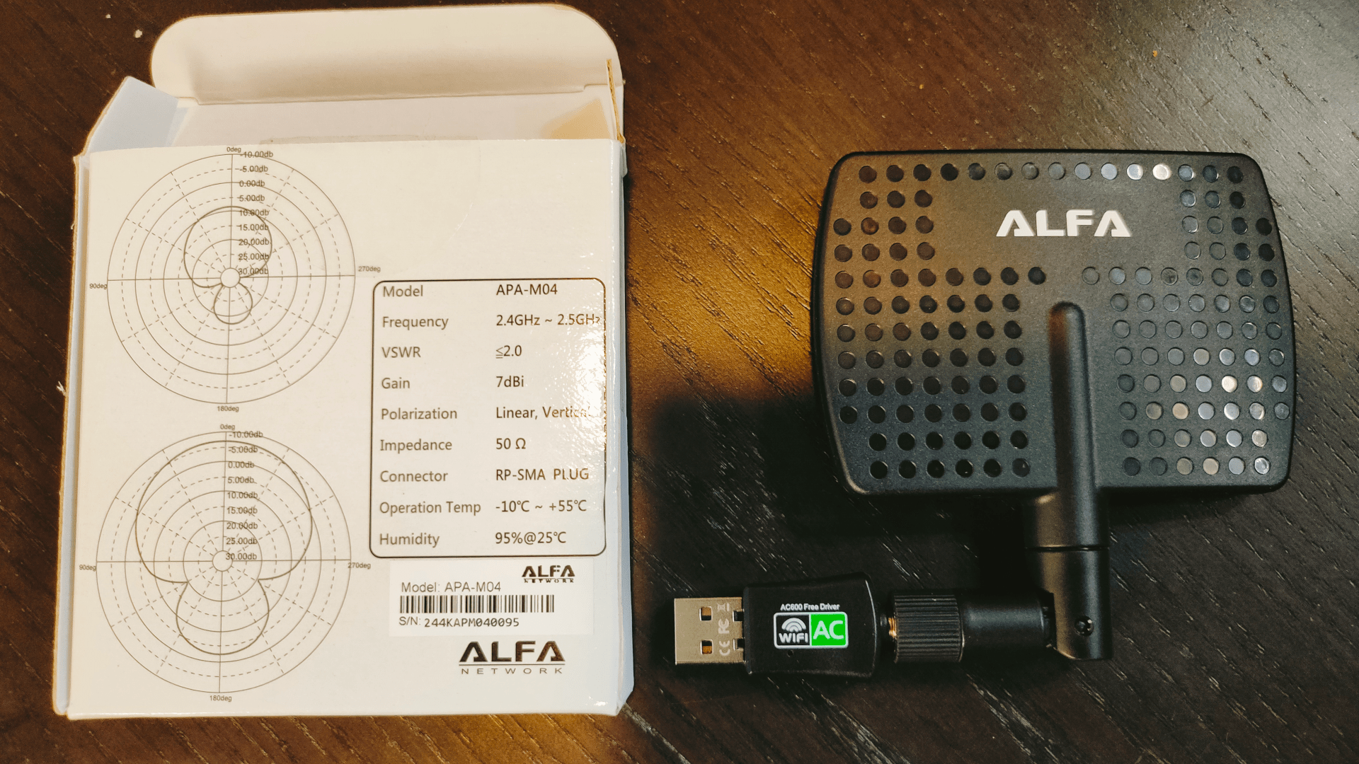
So I used this on my Laptop.
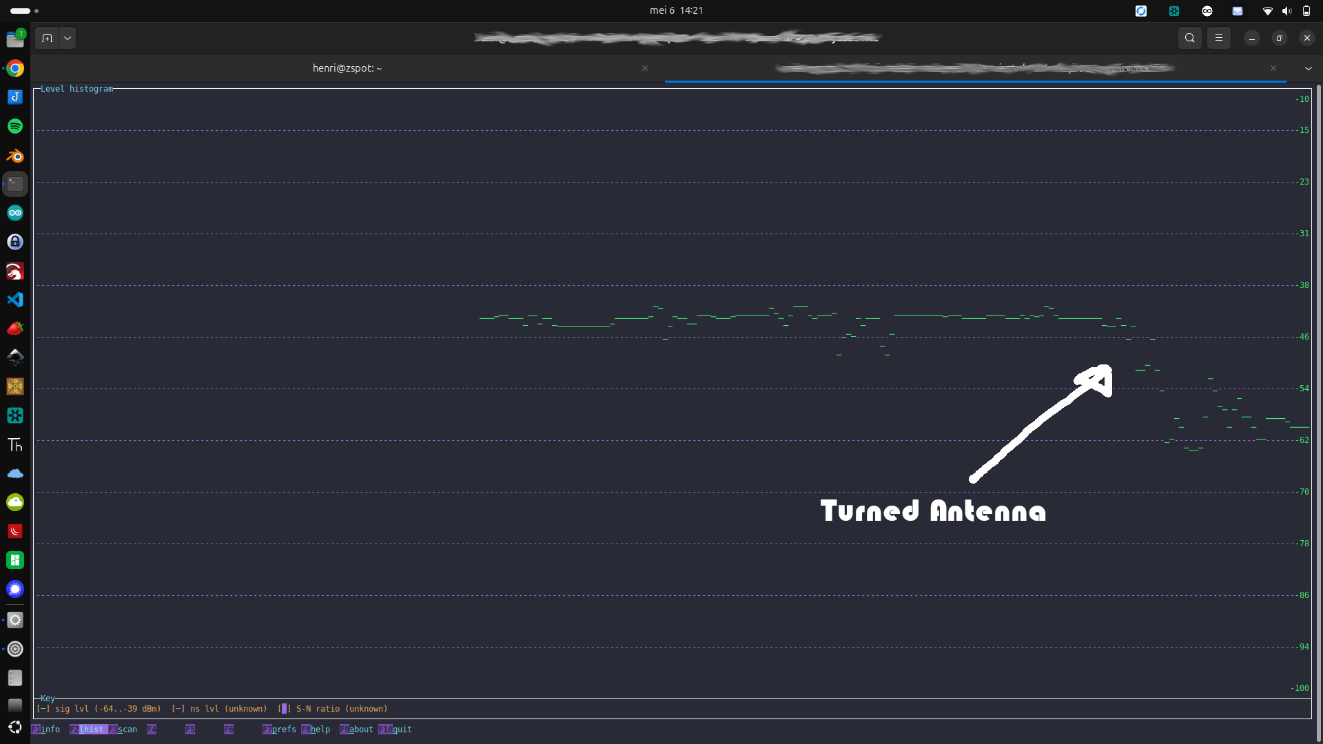
See graphs on the left
This is a directional antenna.
Using Wireshark and wavemon, I could find the direction.
There were only two devices in the direction with the strongest signal. My photo viewer remote, and my mini turntable controller with RFID.
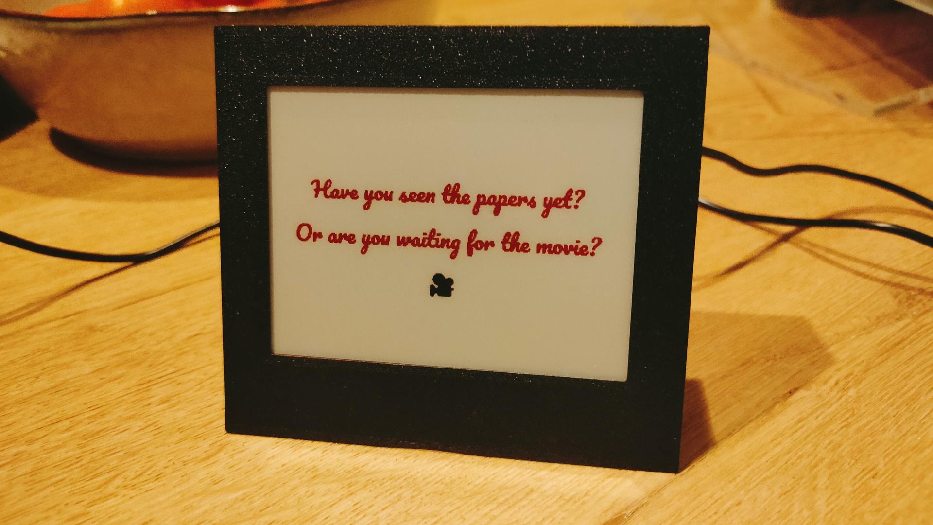
But these devices are working just fine! .. So lets disconnect the power. So it IS the mini recordplayer!
I reversed engineered the workings, and created a python upload script to push images.
Original workings are a mess. Per 4 bit of color, high-low switched in a byte. Black and red separated. Using a till p encoding over curl commands.
My implementation uses a python script called as:
python3 epaper-pusher.py ~/Downloads/Untitled.png
http://10.1.0.99/EPDI_
30 times something like
http://10.1.0.99/ppppppppppppppppppppppppppppppppppppppppppppppppppppppaaaaaaaaaaaaaaaaaaaaaaaaaaaaaaaaaaaaaaaaaaaaaaaaaaaaaaaaaaaaabbbbbbbbbbbbbbbbppppppppppppppppppppppppppppppppppppppppppppppppppppppppppppppppppppppppppppppppppppppppppppppppppppppppppppppppppppppppppppppppppppppppppppppppppppppppppppppppppppppppppppppppppppppppppppppppppppppppppppppppppppppppppppppppppppppppppppppppppppppppppppppppppppppppppppppppppppppppppppppppppppppppppppppppppppppppppppppppppppppppppppppppppppppppppppppppppppppppppppppppppppppppppppppppppppppppppppppppppppppppppppppppppppppppppppppppppppppppppppppppppppppppppppppppppppppppppppppppppppppppppppppppppppppppppppppppppppppppppppppppppppppppppppppppppppppppppppppppppppppppppppppppppppppppppppppppppppppppppppppppppppppppppppppppppppppppppppppppppppppppppppppppppppppppppppppppppppppppppppppppppppppppppppppppppppppppppppppppppppppppppppppppppppppppppppppppppppppppppppppppppppppppppppppppppppppppppppppppppppppppppppppppppppppppppppppppppppppppppppppppppppppppppppppppppppiodaLOAD_
http://10.1.0.99/NEXT_
30 times something like
http://10.1.0.99/pbcdefghijjjjjjffffffoooooooaaabbbbbbeeeedddppppppppppppppppppppppppppppppppppppppppppppppppppppppppppppppppppppppppppppppppppppppppppppppppppppppppppppppppppppppppppppppppppppppppppppppppppppppppppppppppppppppppppppppppppppppppppppppppppppppppppppppppppppppppppppppppppppppppppppppppppppppppppppppppppppppppppppppppppppppppppppppppppppppppppppppppppppppppppppppppppppppppppppppppppppppppppppppppppppppppppppppppppppppppppppppppppppppppppppppppppppppppppppppppppppppppppppppppppppppppppppppppppppppppppppppppppppppppppppppppppppppppppppppppppppppppppppppppppppppppppppppppppppppppppppppppppppppppppppppppppppppppppppppppppppppppppppppppppppppppppppppppppppppppppppppppppppppppppppppppppppppppppppppppppppppppppppppppppppppppppppppppppppppppppppppppppppppppppppppppppppppppppppppppppppppppppppppppppppppppppppppppppppppppppppppppppppppppppppppppppppppppppppppppppppppppppppppppppppppppppppppppppppppppppppppppppppppppppppppppppppppppppppppppppppppppppppppppppppppppppppppppppppppppppppppppppppppppppppiodaLOAD_
http://10.1.0.99/SHOW_
NOTES:
a = 0000
-
-
-
p = 1111 = 15

30 lines with 1000 bytes ( ending with iodaLOAD_ )

black pixels
first block 1
second block 0

red pixels
first block 0
second block 1

white pixels
first block 1
second block 1

PIXEL Example
RBRB
BWBW

First block
1010 - letter K
0101 - Letter F - second nibble = white

Second block
0101 - Letter F
1111 - Letter P - second nibble white
Code
from PIL import Image
import numpy
import requests

url="http://10.1.0.99/"

black_pixels = numpy.zeros((400,300))
red_pixels = numpy.zeros((400,300))


def classify_pixel_color(pixel):
    """
    Classify a pixel as black, white, or red.
    """
    r, g, b = pixel[:3]  # Ignore alpha if present

    # Define thresholds for classification
    if r < 128 and g < 128 and b < 128:
        return 'black'
    elif r > 200 and g > 200 and b > 200:
        return 'white'
    elif r > 128 and g < 100 and b < 100:
        return 'red'
    else:
        return None

def process_image(image_path):
    """
    Process the image and classify its pixels into black, white, or red.
    """
    image = Image.open(image_path)
    image = image.convert("RGB")  # Ensure the image is in RGB mode

    width, height = image.size
    pixel_data = image.load()

    color_counts = {'black': 0, 'white': 0, 'red': 0}

    for y in range (0, 299):
        for x in range (0, 399):
            black_pixels[x][y] = 0
            red_pixels[x][y] = 0

    for y in range(299):
        for x in range(399):
            color = classify_pixel_color(pixel_data[x, y])
            if color:
                color_counts[color] += 1
                if color == 'black':
                    black_pixels[x][y] = 1;
                if color == 'red':
                    red_pixels[x][y] = 1;
                if color == 'white':
                    black_pixels[x][y] = 1;
                    red_pixels[x][y] = 1;

    return color_counts, black_pixels, red_pixels

def number_to_letter(num):
    """
    Translates a number from 0 to 15 into a corresponding letter (a-p).

    Args:
        num (int): The number to translate.

    Returns:
        str: The corresponding letter (a-p).
    """
    if 0 <= num <= 15:
        return chr(ord('a') + num)
    else:
        raise ValueError("Number must be between 0 and 15, inclusive.")

def print_array_in_chunks(array, chunk_size=1001):
    current_chunk = ""
    for item in array:
        # Convert item to string and add to the current chunk
        item_str = str(item)
        if len(current_chunk) + len(item_str) + 1 > chunk_size:
            # Print the current chunk and reset it
            current_chunk += "iodaLOAD_"
            try:
                requests.get(url + current_chunk, verify=False)
                if not response.content:  # Equivalent to expecting an empty reply
                    pass
            except requests.exceptions.RequestException as e:
                # Catch any request-related errors
                pass
            current_chunk = item_str
        else:
            # Append the item to the current chunk
            current_chunk += (item_str)
    current_chunk += "iodaLOAD_"
    # Print any remaining items in the chunk
    if current_chunk:
        try:
            requests.get(url + current_chunk, verify=False)
            if not response.content:  # Equivalent to expecting an empty reply
                pass
        except requests.exceptions.RequestException as e:
            # Catch any request-related errors
            pass


def switch_in_pairs(arr):
    # Loop through the array with a step of 2
    for i in range(0, len(arr) - 1, 2):
        # Swap values at index i and i+1
        arr[i], arr[i + 1] = arr[i + 1], arr[i]
    return arr

if __name__ == "__main__":
    import sys

    if len(sys.argv) < 2:
        print("Usage: python3 script.py <image_path>")
        sys.exit(1)

    image_path = sys.argv[1]
    try:
        color_counts, black_pixels, red_pixels = process_image(image_path)
        try:
            requests.get(url + "EPDI_" , verify=False)
            if not response.content:  # Equivalent to expecting an empty reply
                pass
        except requests.exceptions.RequestException as e:
            # Catch any request-related errors
            pass


        lines=[]
        for y in range(300):
            for x in range(0,399,4):
                first = red_pixels[x][y]
                second = red_pixels[x+1][y]
                thirth = red_pixels[x+2][y]
                fourth = red_pixels[x+3][y]
                nibble = 0
                if (first ==  1):
                        nibble = nibble + 8
                if (second ==  1):
                        nibble = nibble + 4
                if (thirth ==  1):
                        nibble = nibble + 2
                if (fourth ==  1):
                        nibble = nibble + 1
                lines.append(number_to_letter(nibble))
        switched_array = switch_in_pairs(lines)
        print_array_in_chunks(switched_array)
        try:
            requests.get(url + "NEXT_" , verify=False)
            if not response.content:  # Equivalent to expecting an empty reply
                pass
        except requests.exceptions.RequestException as e:
            # Catch any request-related errors
            pass
        lines=[]
        for y in range(300):
            for x in range(0,399,4):
                first = black_pixels[x][y]
                second = black_pixels[x+1][y]
                thirth = black_pixels[x+2][y]
                fourth = black_pixels[x+3][y]
                nibble = 0
                if (first ==  1):
                        nibble = nibble + 8
                if (second ==  1):
                        nibble = nibble + 4
                if (thirth ==  1):
                        nibble = nibble + 2
                if (fourth ==  1):
                        nibble = nibble + 1
                lines.append(number_to_letter(nibble))
        switched_array = switch_in_pairs(lines)
        print_array_in_chunks(switched_array)

        try:
            requests.get(url + "SHOW_" , verify=False)
            if not response.content:  # Equivalent to expecting an empty reply
                pass
        except requests.exceptions.RequestException as e:
            # Catch any request-related errors
            pass

    except Exception as e:
        pass
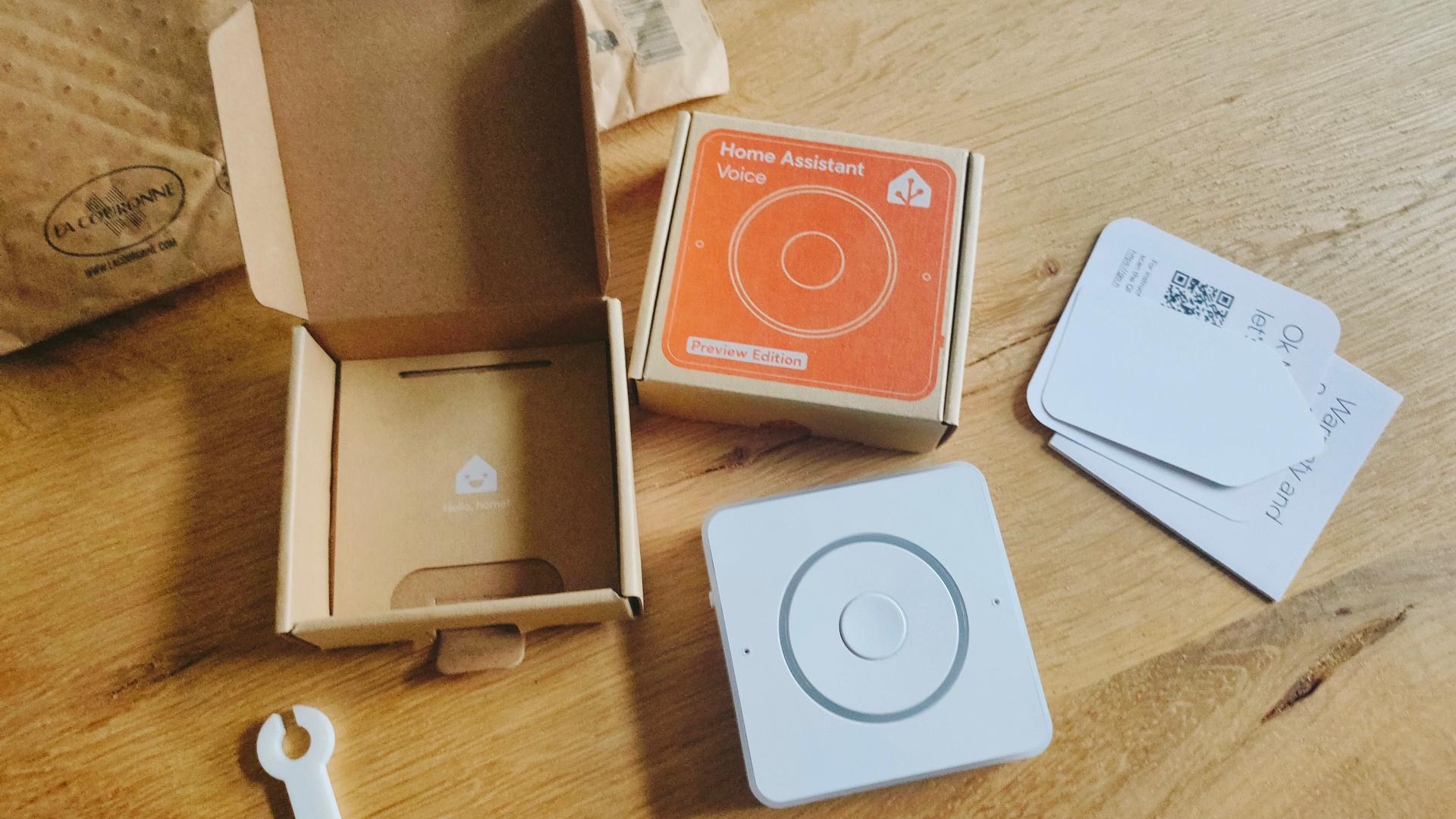
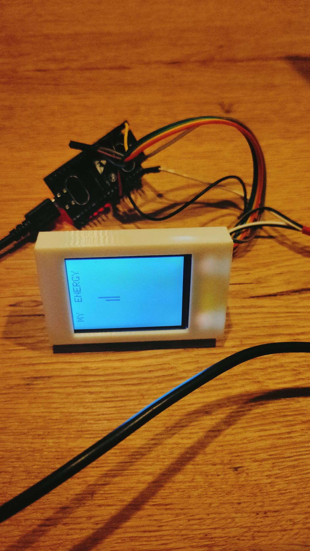
This is a Non-Cloud solution like Alexa and Google devices. I only could play with it for a few minutes because I was working on Arduino code with an ILI9341 Display and a BME280 (Temperature/Humidity/Air pressure).
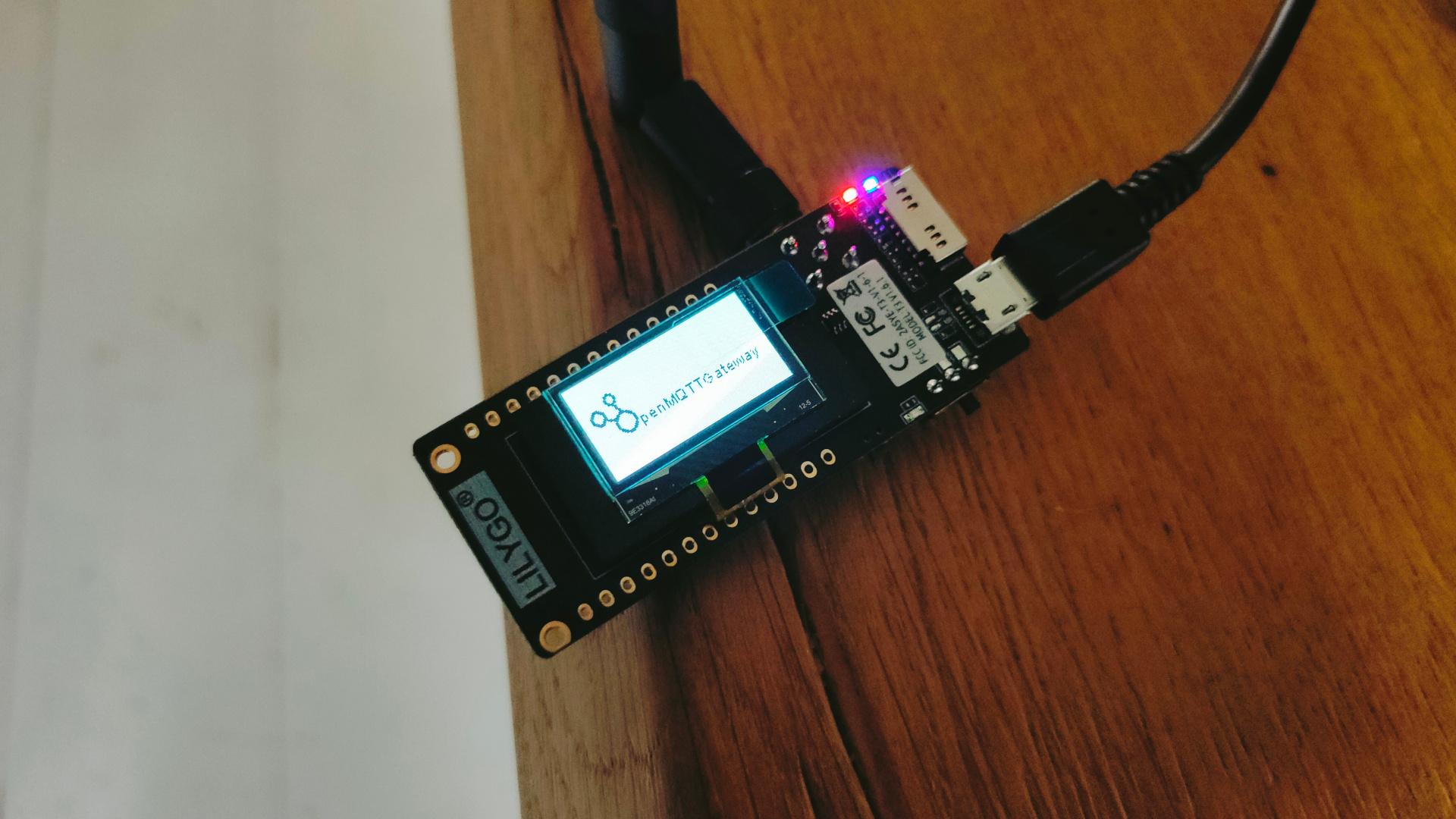
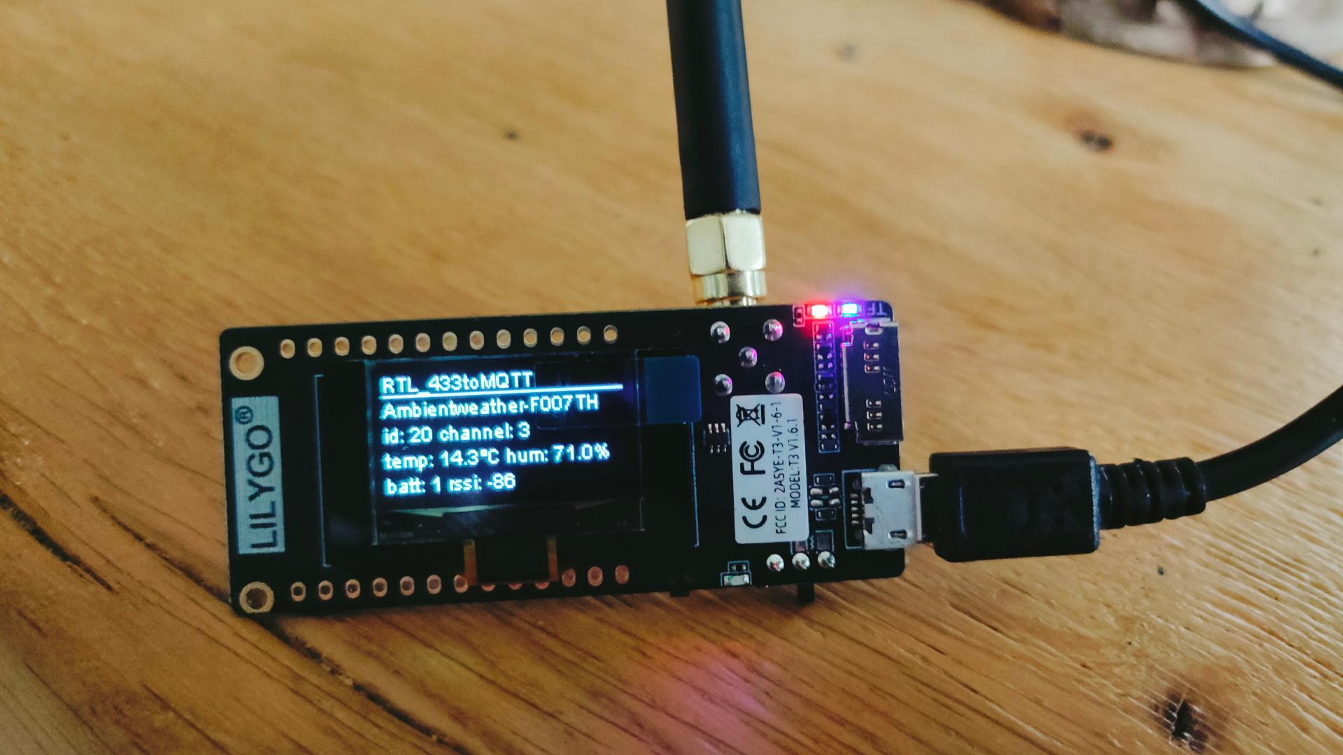
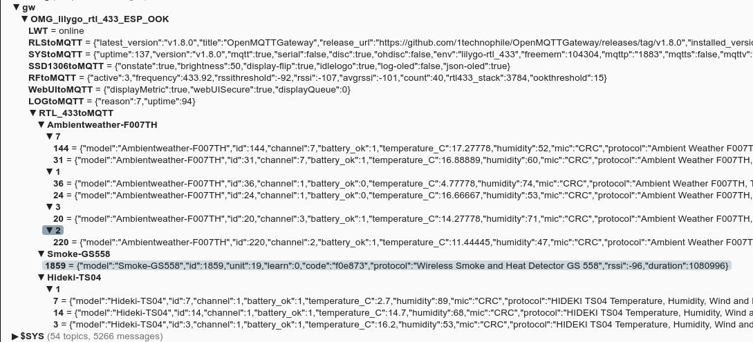
Today I got some new goodies in, one of these is a LilyGO LoRa display which works on 433 Mhz.
I flashed OpenMQTTGateway on this device.
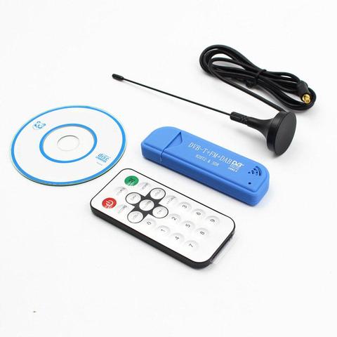
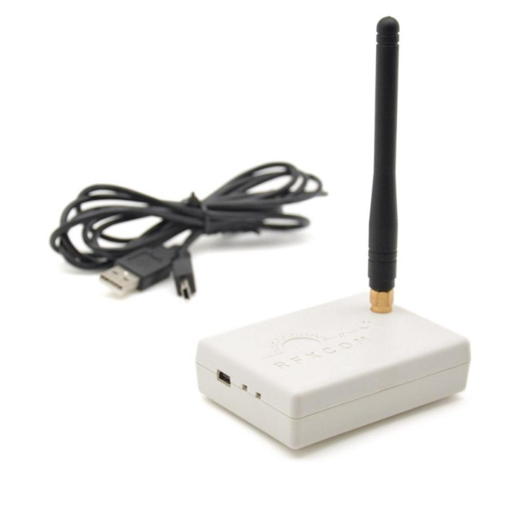
In the past, I posted about the RFCOM Gateway using Domoticz. This runs on a Raspberry Pi. While looking for alternatives, I found a rtl-sdr solution.
While working on a client project, I tested multiple displays.
ILI9341
1.3inch SPI TFT LCD Display RGB (ST7789)
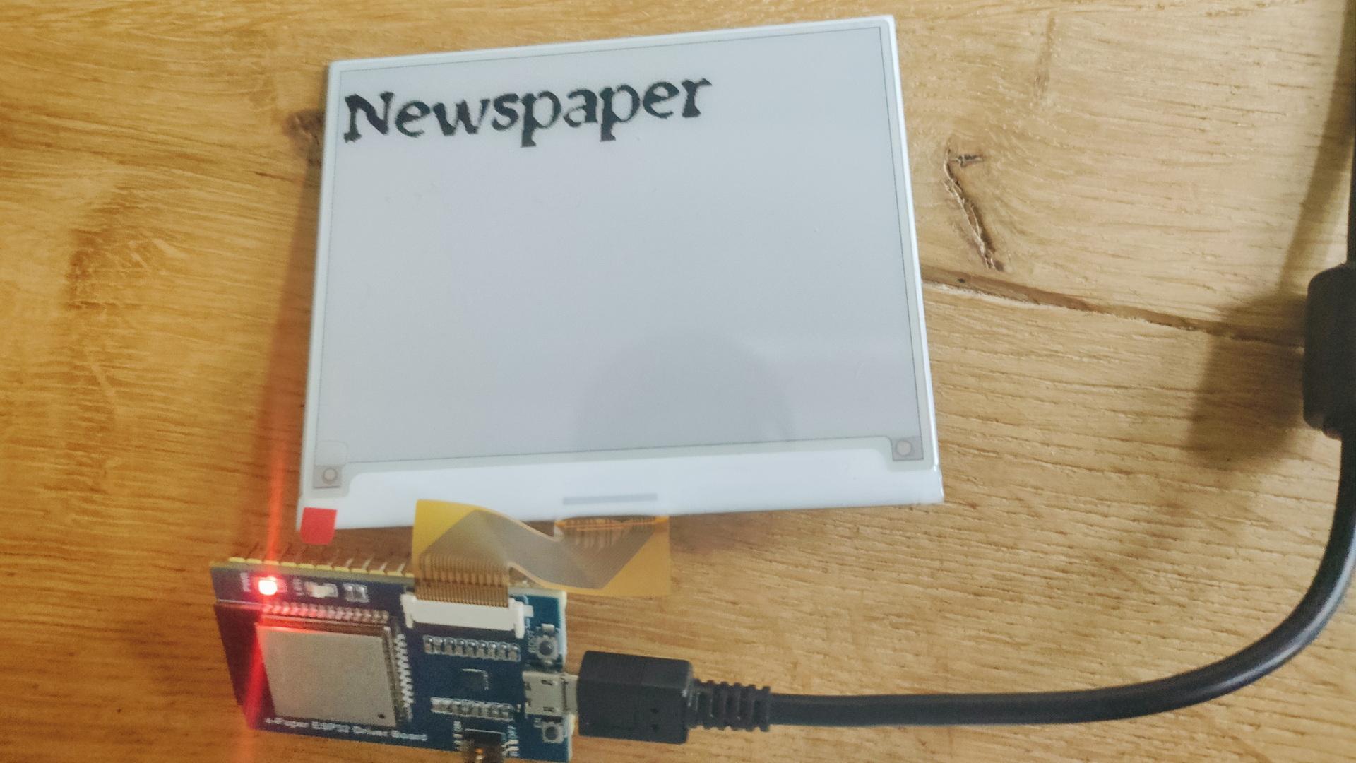
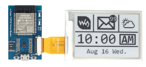
Waveshare 4.2 Epaper with ESP32 Controller
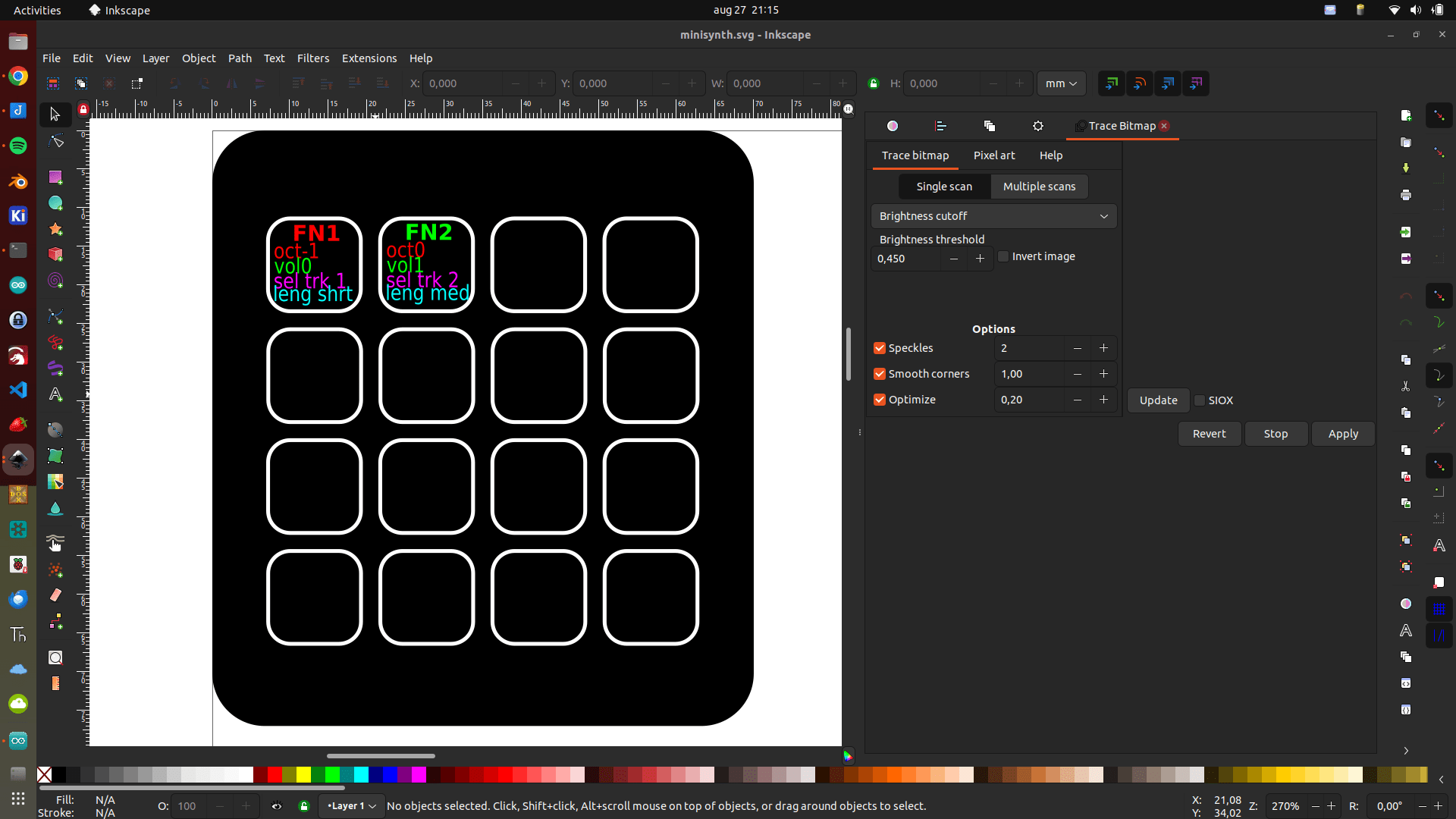
I thought it was fun to connect the Epaper to ESPHome.
This probably ends up being a Quote displayer
Universal e-Paper Driver Board with WiFi / Bluetooth SoC ESP32 onboard, supports various Waveshare SPI e-Paper raw panels
It was not without problems. For example, the ESPHome editor gave squiggly lines under type. This has to be changed in the libraries. (Already notified developers)
model: 4.20in-V2 does not work .. use model: 4.20in-v2
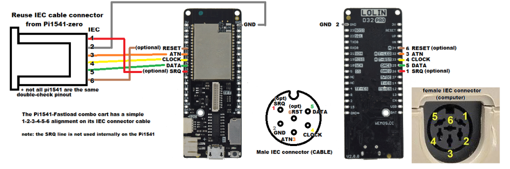
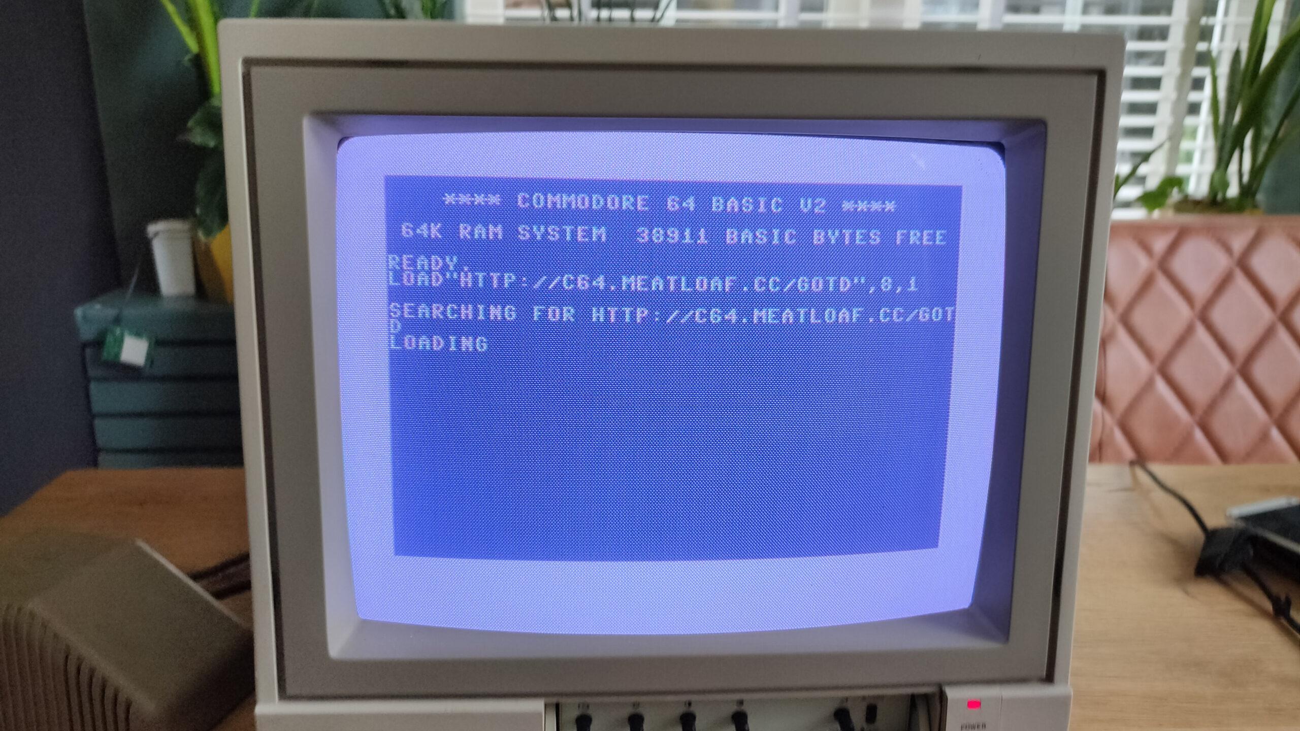
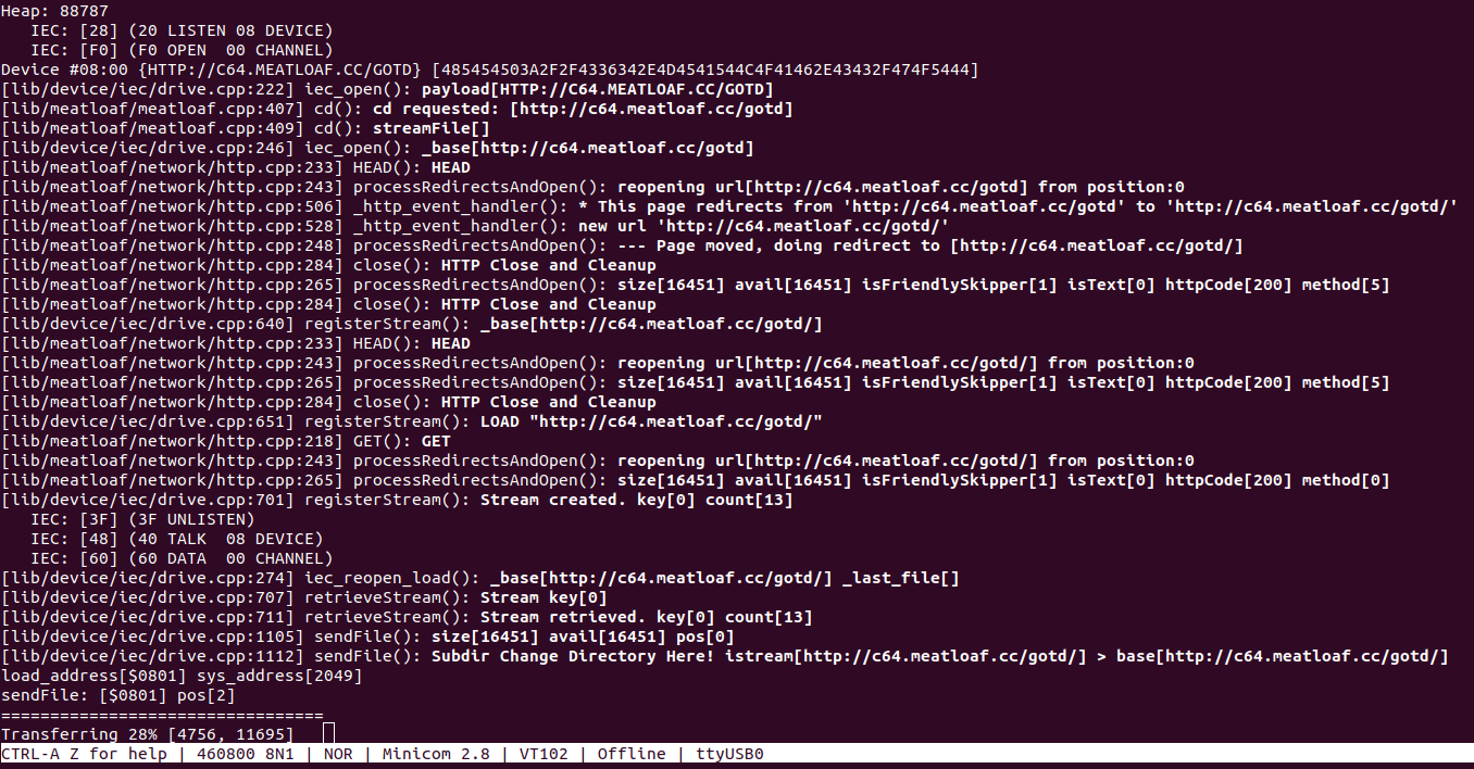
Emulates a floppy drive: Meatloaf plugs into the Commodore 64’s IEC serial port and acts like a virtual floppy drive. This allows you to load software and data stored on its internal flash memory, sd card, or stream it via WiFi using various protocols from servers all over the world.
Supports multiple virtual drives: Unlike a single floppy drive, Meatloaf can be configured to emulate up to 26 virtual drives (IDs 4-30). Each virtual drive can have a different disk image loaded, essentially offering the equivalent of having thousands of floppies connected to your C64.
Supports additional virtual device types: Printers, a network interface, and more.
Connects to the internet: Meatloaf also functions as a WiFi modem, enabling your Commodore 64 to connect to Telnet BBS (bulletin board systems) for communication and sharing information.
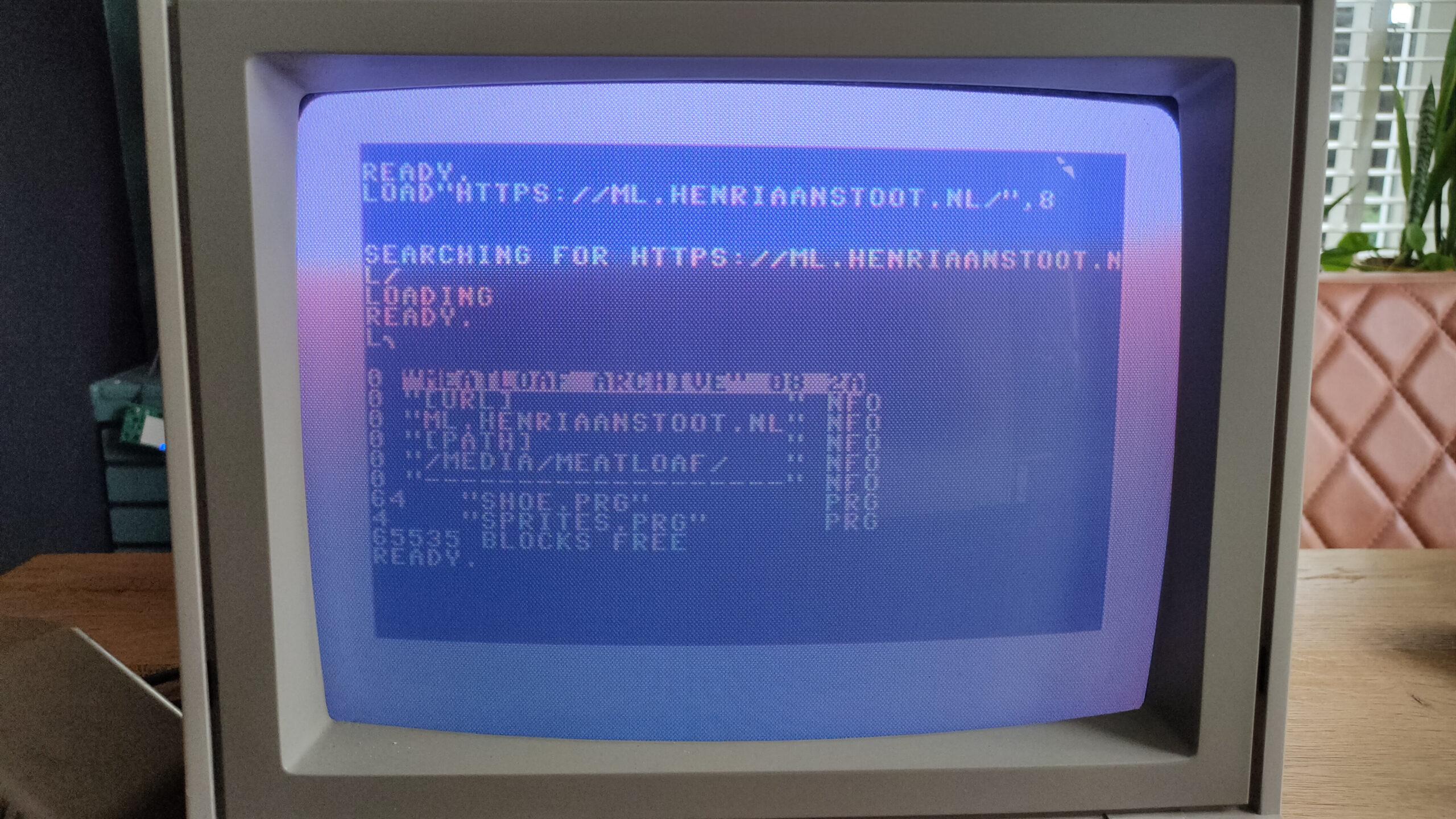
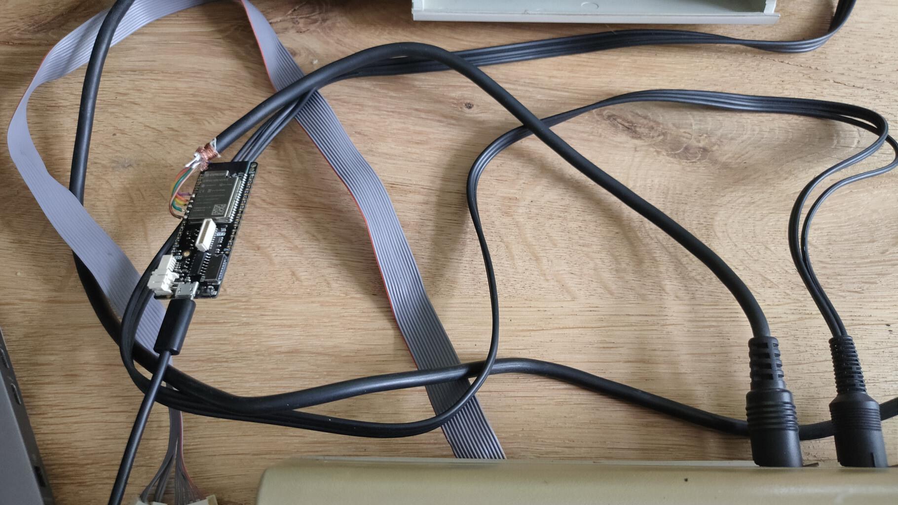
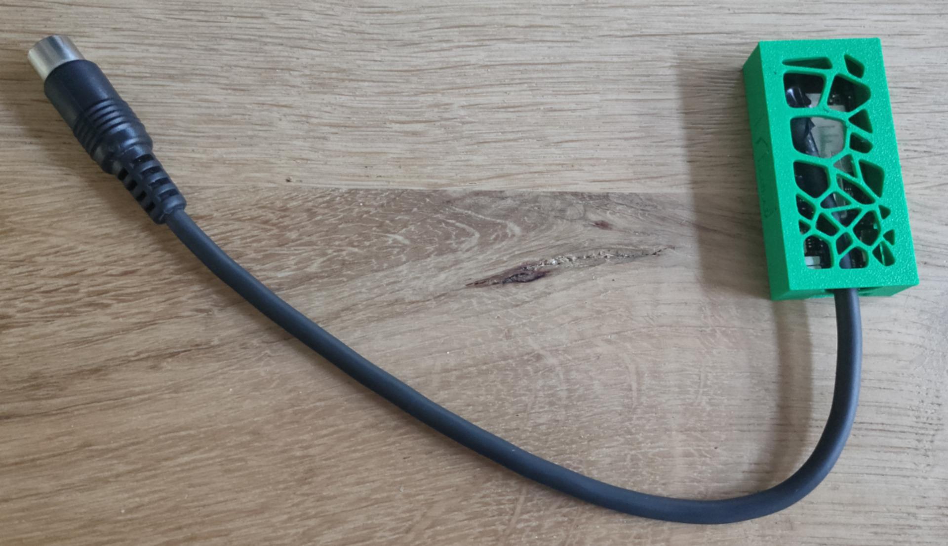
load from urldebug outputmy own repo testOnly a Lolin D32 and a cable with din connector.
Socket connect to server, enter number and get reply test.
server.py
import socket
import threading

# Define the host and port
HOST = '0.0.0.0'  # Localhost (change as needed)
PORT = 65432        # Port to listen on (non-privileged ports are > 1023)

# Function to handle each client connection
def handle_client(conn, addr):
    print(f"Connected by {addr}")

    # Send a thank you message to the client upon connection
    thank_you_message = "Thank you for connecting! Please enter a number:\n"
    conn.sendall(thank_you_message.encode('utf-8'))

    while True:
        try:
            data = conn.recv(1024)
            if not data:
                break

            # Decode the received data
            received_number = data.decode('utf-8').strip()
            print(f"Received from {addr}: {received_number}")

            # Try to convert the received data to an integer
            try:
                number = int(received_number)
                response = f"The double of {number} is {number * 2}\n"
            except ValueError:
                response = "Please enter a valid number.\n"

            # Send the response back to the client
            conn.sendall(response.encode('utf-8'))
        except ConnectionResetError:
            print(f"Connection with {addr} lost.")
            break

    conn.close()
    print(f"Connection with {addr} closed.")

# Function to start the server and listen for connections
def start_server():
    # Create a socket object
    server = socket.socket(socket.AF_INET, socket.SOCK_STREAM)

    # Bind the socket to the host and port
    server.bind((HOST, PORT))

    # Start listening with a maximum backlog of 5 connections
    server.listen(5)
    print(f"Server listening on {HOST}:{PORT}")

    while True:
        # Accept a new connection
        conn, addr = server.accept()

        # Create a new thread to handle the client connection
        client_thread = threading.Thread(target=handle_client, args=(conn, addr))
        client_thread.start()

# Run the server
if __name__ == "__main__":
    start_server()
python-client.py
import socket

# Define the server host and port
HOST = 'IPNUMBERSERVER'  # The server's hostname or IP address
PORT = 65432        # The port used by the server

def start_client():
    # Create a socket object
    client = socket.socket(socket.AF_INET, socket.SOCK_STREAM)

    # Connect to the server
    client.connect((HOST, PORT))

    # Receive and print the welcome message from the server
    welcome_message = client.recv(1024).decode('utf-8')
    print(welcome_message)

    while True:
        # Enter a number and send it to the server
        number = input("Enter a number (or type 'exit' to quit): ")

        if number.lower() == 'exit':
            print("Closing connection...")
            break

        client.sendall(number.encode('utf-8'))

        # Receive the response from the server and print it
        response = client.recv(1024).decode('utf-8')
        print(response)

    # Close the connection after the loop ends
    client.close()

# Run the client
if __name__ == "__main__":
    start_client()
arduino-client.ino
#include <ESP8266WiFi.h> // For ESP8266
//#include <WiFi.h>       // For ESP32

// Replace with your network credentials
const char* ssid     = "your_SSID";     // Replace with your network SSID (name)
const char* password = "your_PASSWORD"; // Replace with your network password

// Define the server's IP address and port
const char* host = "192.168.1.100"; // Replace with your server's IP address
const int port = 65432;             // Server port

WiFiClient client;

void setup() {
  Serial.begin(115200);
  delay(10);

  // Connect to WiFi
  Serial.println();
  Serial.print("Connecting to ");
  Serial.println(ssid);

  WiFi.begin(ssid, password);

  while (WiFi.status() != WL_CONNECTED) {
    delay(1000);
    Serial.print(".");
  }

  Serial.println();
  Serial.println("WiFi connected.");
  Serial.println("IP address: ");
  Serial.println(WiFi.localIP());

  // Connect to the server
  Serial.print("Connecting to server at ");
  Serial.print(host);
  Serial.print(":");
  Serial.println(port);

  if (client.connect(host, port)) {
    Serial.println("Connected to server!");

    // Wait for the welcome message from the server
    while (client.available() == 0);

    // Read and print the welcome message
    while (client.available()) {
      char c = client.read();
      Serial.print(c);
    }
  } else {
    Serial.println("Connection failed.");
  }
}
void loop() {
  // Check if connected to the server
  if (client.connected()) {
    // Check if there is any serial input from the user
    if (Serial.available() > 0) {
      String input = Serial.readStringUntil('\n');
      input.trim();

      if (input.equalsIgnoreCase("exit")) {
        Serial.println("Closing connection...");
        client.stop(); // Disconnect from the server
        while (true);  // Stop the loop
      }

      // Send the number to the server
      client.println(input);

      // Wait for the server's response
      while (client.available() == 0);

      // Read and print the server's response
      while (client.available()) {
        char c = client.read();
        Serial.print(c);
      }
    }
  } else {
    Serial.println("Disconnected from server.");
    while (true); // Stop the loop
  }
}
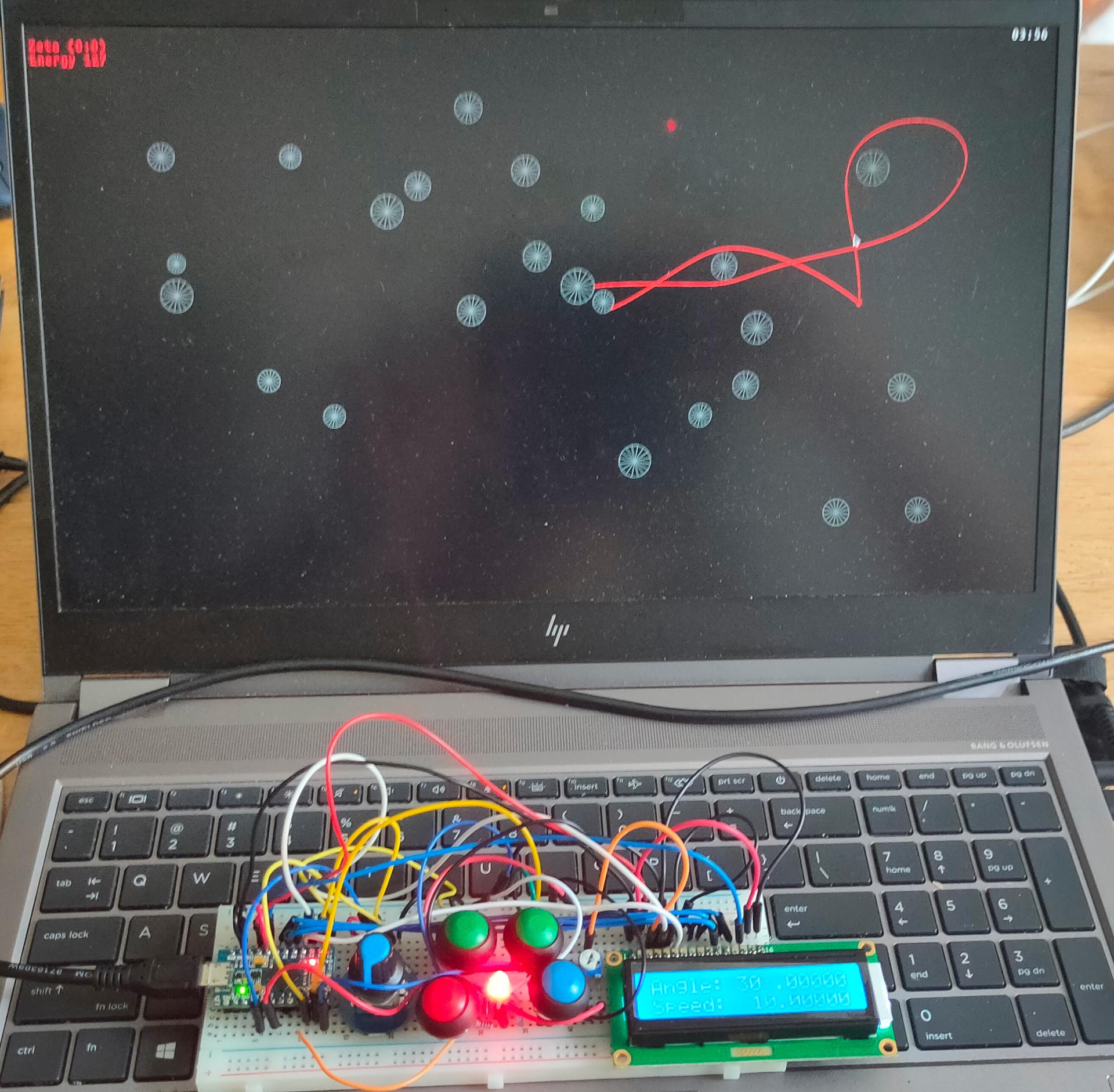
Saw a cool game a while ago, and found some old code. There was no schematic, so I had to reverse engineer it using the Arduino code. This one uses a Micro Pro.
Build a working version, now I can use this as base to create other games. But first i’m going to rebuild it so it can use Wifi and uses a Lipo Battery. Making it usable without wires.
Rotary – set angle/speed (Press resets)
Blue – toggle angle or speed ( was rotary press )
Green – select digit to change
Red – Fire
Led – not completely working yet, shows color of player Wil be changed to addressable leds with more functions (Player color, energy warning and more)
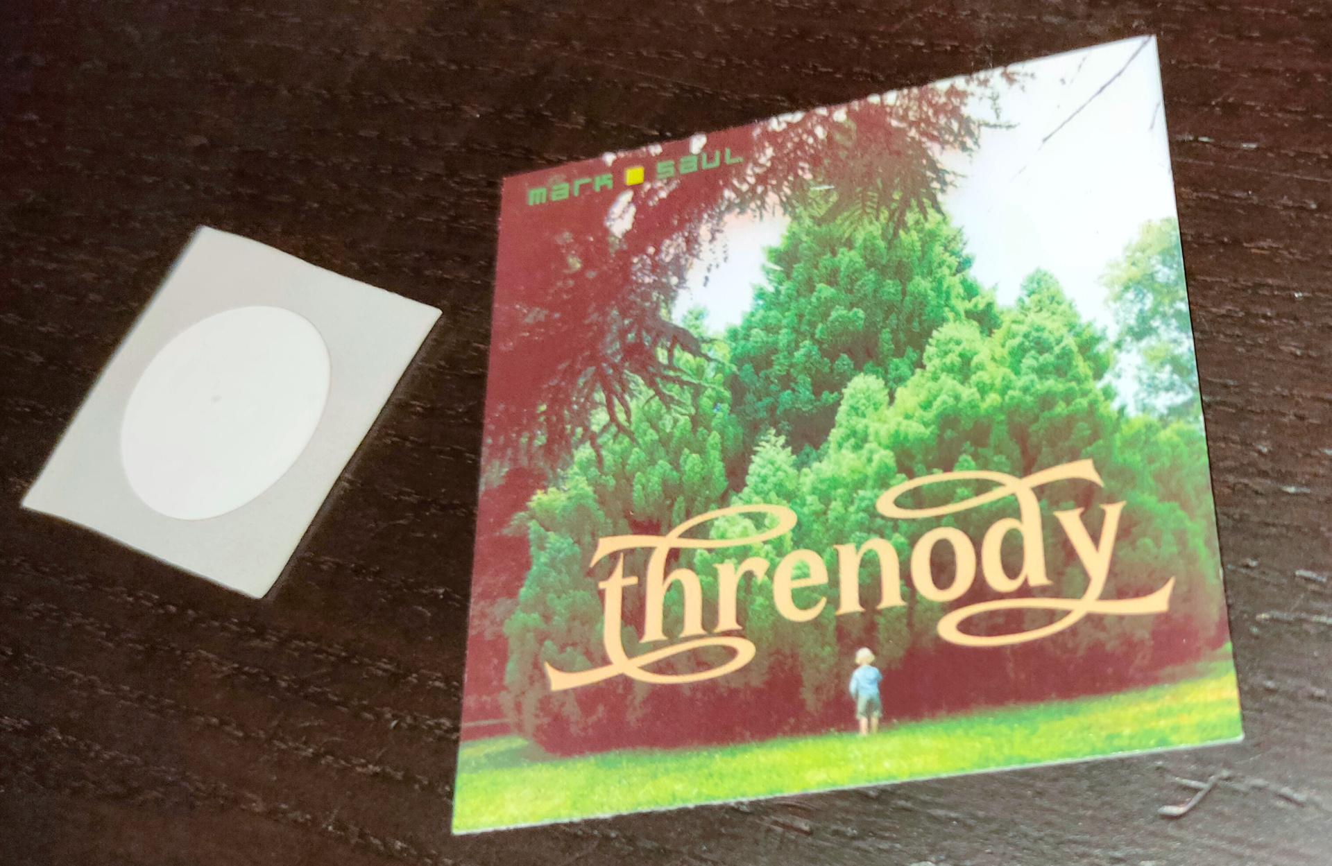
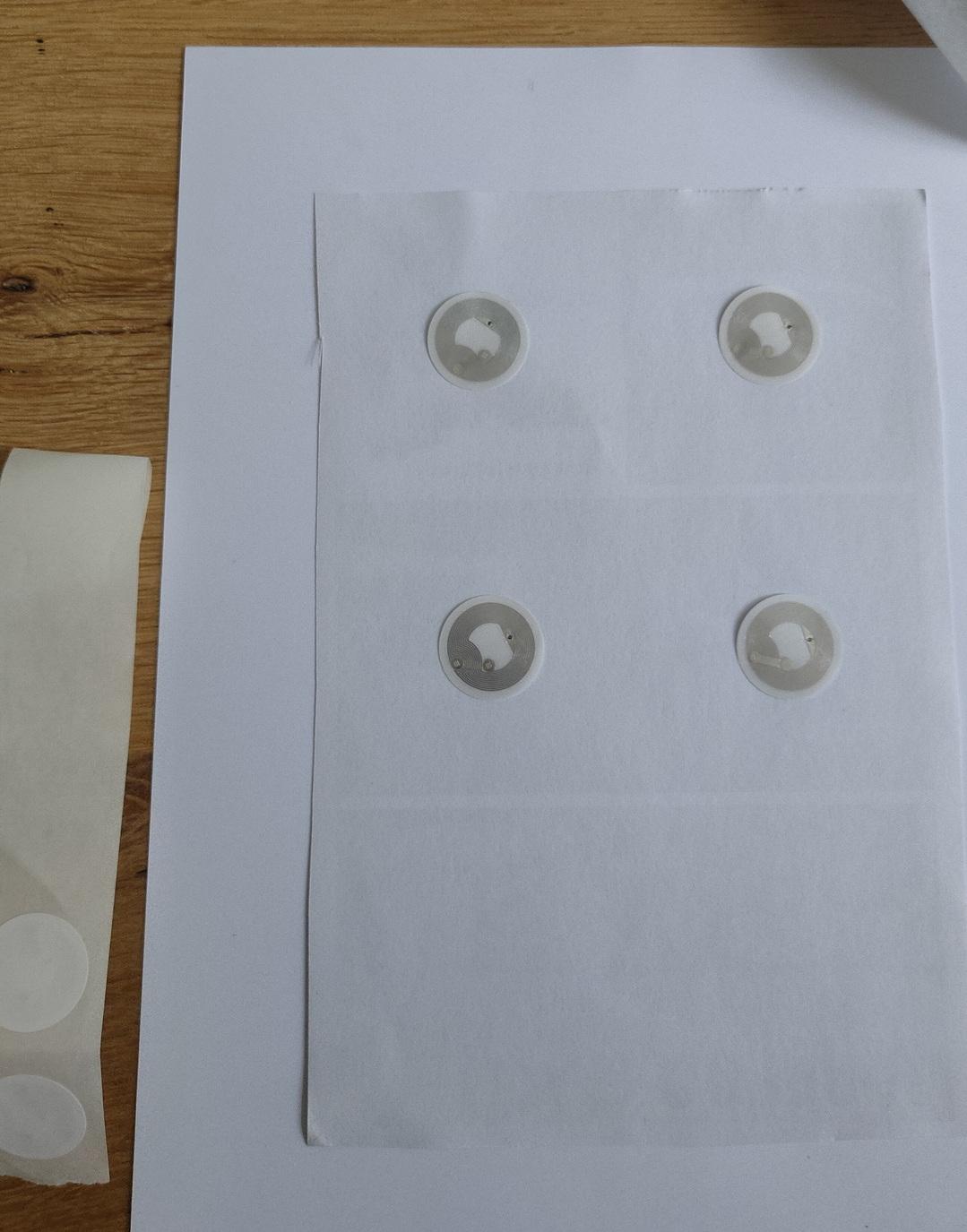
The next iteration of my Rfid controller will have a write function for the RFID tags.
Stick a tag on a cover art piece of cardboard. (see below)
Read path from data sector.
Send path to player automation
Send path to program using MQTT or website if needed.
Back of printed sticker, to stick on 250gr paper below
Not sure yet, also want to implement a wifi manager on the wemos.
Changes on above idea:
Paths are too long, I could not work out how to create a working program using this.
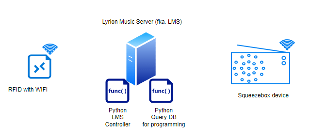
I stopped using paths, instead I’m using the Logitech media server album IDs.
Using two python scripts, I can use one for programming the card, and another script to control LMS.
How does it work
RFid device is connected to the network.
Start query.py on your LMS server. Search for an album name, it will present an ID and Album name in a list. Enter the ID you want to program, or 0 to exit. (This will also reset the programming mode)
Place an empty or previously programmed tag on the device. It will write the album ID on the tag.
Then it will start the album. Changing the tags will also just change the album playing.
(NOTE: My genre spotify player still works using this method, using the same device)
A second python script will read the Mqtt topic and control the Squeezebox player.
Python Code DB Query
import sqlite3
#paho-mqtt
import paho.mqtt.publish as publish

host = "IPMQTTBROKER"
port = 1883
topic = "spotify/rfid/in/write"
auth = {'username': 'xxxx','password': 'xxxxx'}
client_id = "spotithing"

def readSqliteTable(albumname):
    try:
        sqliteConnection = sqlite3.connect('/var/lib/squeezeboxserver/cache/library.db')
        cursor = sqliteConnection.cursor()
        albumname = "%" + albumname + "%"
        cursor.execute("select * from albums where title Like ?",
               (albumname,))
        records = cursor.fetchall()
        for row in records:
            print("Id: ", row[0],row[1])
        cursor.close()

    except sqlite3.Error as error:
        print("Failed to read data from sqlite table", error)
    finally:
        if sqliteConnection:
            sqliteConnection.close()

album = input("Album name ? ")
readSqliteTable(album)

number = input("Enter ID or 0 to quit : ")
publish.single(topic, "00000" , qos=1, hostname=host, port=port,
        auth=auth, client_id=client_id)
if number == 0:
        exit()
publish.single(topic, number, qos=1, hostname=host, port=port,
        auth=auth, client_id=client_id)
print("Program your tag")
print("Reset/disable writing using exit with 0!")
Python Code Controller (this one needs to be running at all times)
import paho.mqtt.client as mqtt
import urllib.request

def on_connect(client, userdata, flags, rc):
        print("Connected with result code {0}".format(str(rc)))
        client.subscribe("spotify/rfid/idlms")

def on_message(client, userdata, msg):
        print("Message received-> " + msg.topic + " " + str(msg.payload))  # Print a received msg
        urllib.request.urlopen("http://IPADDRESLMS:9000/anyurl?p0=playlistcontrol&p1=album_id:" + msg.payload.decode() + "&p2=cmd:load&player=b8:27:eb:11:16:ab")
#NOTE also change b8:27:eb:11:16:ab into you players MACAddress!

client = mqtt.Client("digi_mqtt_test")
client.on_connect = on_connect
client.on_message = on_message
client.connect('IPMQTTBROKER', 1883)
client.loop_forever()
Arduino Code (see schematic in other post)
#include <Arduino.h>
#include <SPI.h>
#include <MFRC522.h>
#include <ESP8266WiFi.h>
#include <WiFiClient.h>
#include <PubSubClient.h>
#define SS_PIN 15
#define RST_PIN 0
MFRC522 mfrc522(SS_PIN, RST_PIN);
  MFRC522::StatusCode status; //variable to get card status
  byte buffer[18];  //data transfer buffer (16+2 bytes data+CRC)
  byte size = sizeof(buffer);
  uint8_t pageAddr = 0x06;  //In this example we will write/read 16 bytes (page 6,7,8 and 9).
                            //Ultraligth mem = 16 pages. 4 bytes per page.
                            //Pages 0 to 4 are for special functions.
unsigned long cardId = 0;
WiFiClient net;
PubSubClient client(net);
const char* mqtt_server = "IPMQTTBROKER";
const char* ssid = "MYSSID";
const char* password = "MYSSIDPASS";
String topicStr = "";
byte buffer2[8];

boolean Rflag=false;
int r_len;
char payload[5];
byte value[5];
void setup() {
  Serial.begin(9600);
  SPI.begin();
  mfrc522.PCD_Init();
  WiFi.mode(WIFI_AP_STA);
  WiFi.begin(ssid, password);
  client.setServer(mqtt_server, 1883);
     delay(100);
    client.setCallback(callback);
      delay(100);
    client.subscribe("spotify/rfid/in/#");
}
void reconnect() {
  while (WiFi.waitForConnectResult() != WL_CONNECTED) {
  }
  while (!client.connected()) {
    String clientId = "rfid-";
    clientId += String(random(0xffff), HEX);
    if (!client.connect(clientId.c_str(), "rfidclient", "...")) {
      Serial.print("failed, rc=");
      Serial.print(client.state());
      delay(5000);
    }
  }
  client.subscribe("spotify/rfid/in/#");
}
void callback(char* topic, byte* payload, unsigned int length) {

  Serial.print(F("Called"));
   Rflag=true; //will use in main loop
   r_len=length; //will use in main loop
   Serial.print("length message received in callback= ");
   Serial.println(length);
   int j=0;
     for (j;j<length;j++) {
       buffer2[j]=payload[j];
       }
if (r_len < 3) {
  Rflag=false;
  Serial.print(F("Set false"));
}
buffer2[j]='\0'; //terminate string
}

void loop() {
    if (!client.connected()) {
    reconnect();
  }
  client.loop();
  if (!mfrc522.PICC_IsNewCardPresent()) {
    return;
  }
  if (!mfrc522.PICC_ReadCardSerial()) {
    return;
  }
if (Rflag) {
        for (int i=0; i < 4; i++) {
    //data is writen in blocks of 4 bytes (4 bytes per page)
    status = (MFRC522::StatusCode) mfrc522.MIFARE_Ultralight_Write(pageAddr+i, &buffer2[i*4], 4);
    if (status != MFRC522::STATUS_OK) {
      Serial.print(F("MIFARE_Read() failed: (W) "));
      Serial.println(mfrc522.GetStatusCodeName(status));
      return;
    }
  }
  Serial.println(F("MIFARE_Ultralight_Write() OK "));
  Serial.println();
  Rflag=false;
}
  cardId = getCardId();
  char buffer3[10];
  sprintf(buffer3, "%lu", cardId);
  client.publish("spotify/rfid/id", buffer3);
  // Read data ***************************************************
  Serial.println(F("Reading data ... "));
  //data in 4 block is readed at once.
  status = (MFRC522::StatusCode) mfrc522.MIFARE_Read(pageAddr, buffer, &size);
  if (status != MFRC522::STATUS_OK) {
    Serial.println(F("MIFARE_Read() failed: (R)"));
    Serial.println(mfrc522.GetStatusCodeName(status));
    return;
  }

  Serial.println(F("Read data: "));
  //Dump a byte array to Serial
  for (byte i = 0; i < 5; i++) {
    Serial.write(buffer[i]);
       buffer2[i]=buffer[i];
    }
  client.publish("spotify/rfid/idlms", buffer,5);
  delay(1000);
  mfrc522.PICC_HaltA();
}

unsigned long getCardId() {
  byte readCard[4];
  for (int i = 0; i < 4; i++) {
    readCard[i] = mfrc522.uid.uidByte[i];
  }
  return (unsigned long)readCard[0] << 24
    | (unsigned long)readCard[1] << 16
    | (unsigned long)readCard[2] << 8
    | (unsigned long)readCard[3];
}
Today we worked on this project again. (Bigred and me)
There were some problems we needed to fix since last time:
It was quite hard to get the correct parts. Our display connector was only fitted with connection pins on the wrong side of the connector. (up/down) So I bought a connector with both positions populated. So we had to replace this hard to solder (40 pin) connector.
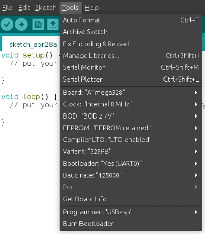
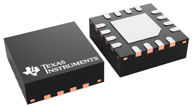
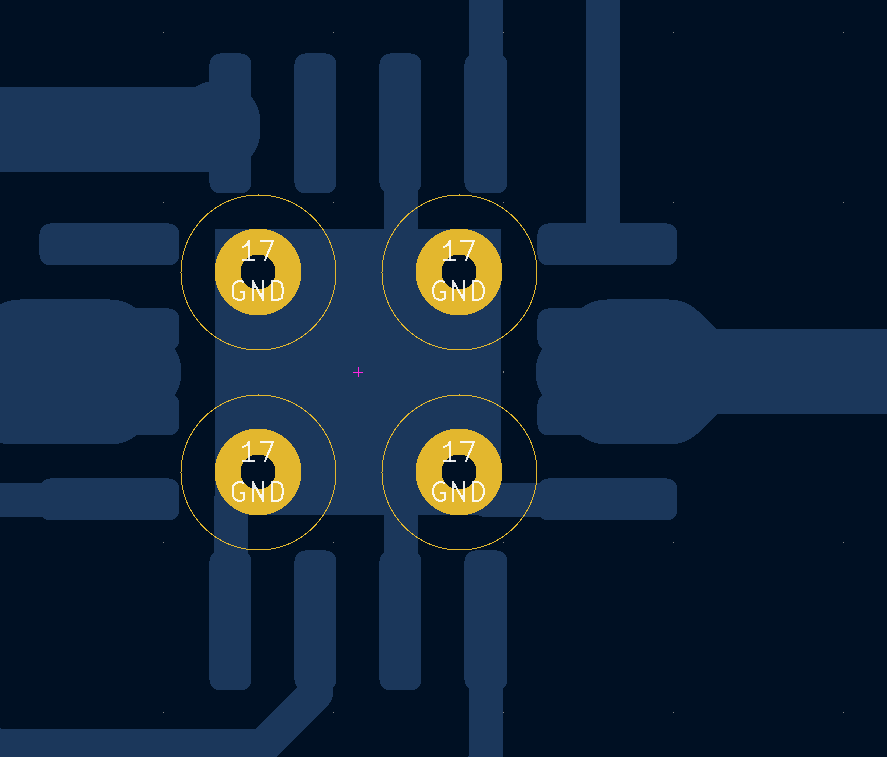
It was not clear what the orientation should be of the atmega328pb. We looked at the pinout, and followed the VCC/GND. But these are also available of the opposite side of the chip. (We missed that) Later, we saw a tiny line on the PCB, which showed the pin 1 placement. So we had to remove and replace the chip. When turning on the power, (with incorrect placement) probably fried R5 (10k resistor), on both our boards. Had to replace those also.
Programming the atmega328pb was not easy, see below fixes.
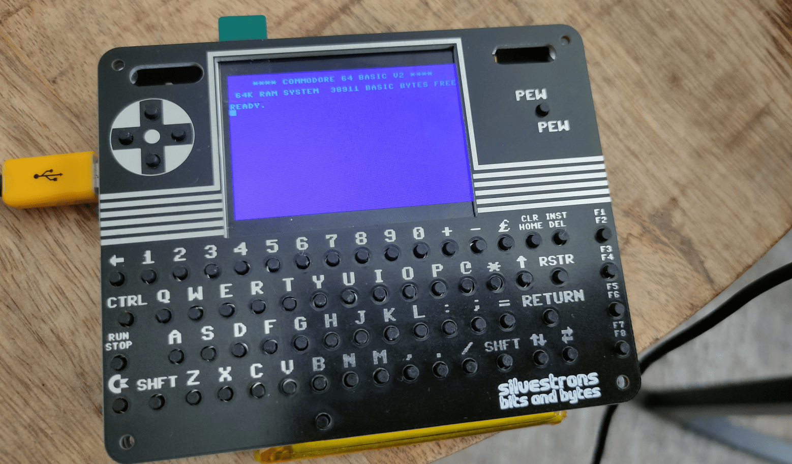
Compiling the pico firmware resulted in a black screen. Below the fixes I had to make to get the screen working.
Other things still to fix.
Bigreds screen.
atmega328p didn’t work for Bigred, so probably needs to replace with the pb version.
My battery controller is not charging. See bottom of page
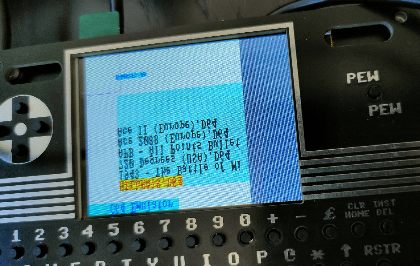
Some of my buttons are working. The pewpew and some of the cursor keys (not as I expect, there are some up/down issues) And none of the other keys are working.
Some other things we noticed.
sdcard: remove partitions, format using mkfs.exfat Create a c64 directory on this filesystem where you can put the d64 files!
0402 SMD is far too small for me. There is enough room on the board to use 0805 for example. Even THT is possible, there are only a few components.
Some components are TOO close together, removing a component resulted in other small parts disconnecting also.
My friend Bigred said: If I can see it, I can solder it. But it is not easy. This probably keeps a lot of people from building it!