Model by wayneclarke, structure paint is cement look from Havo Holland.
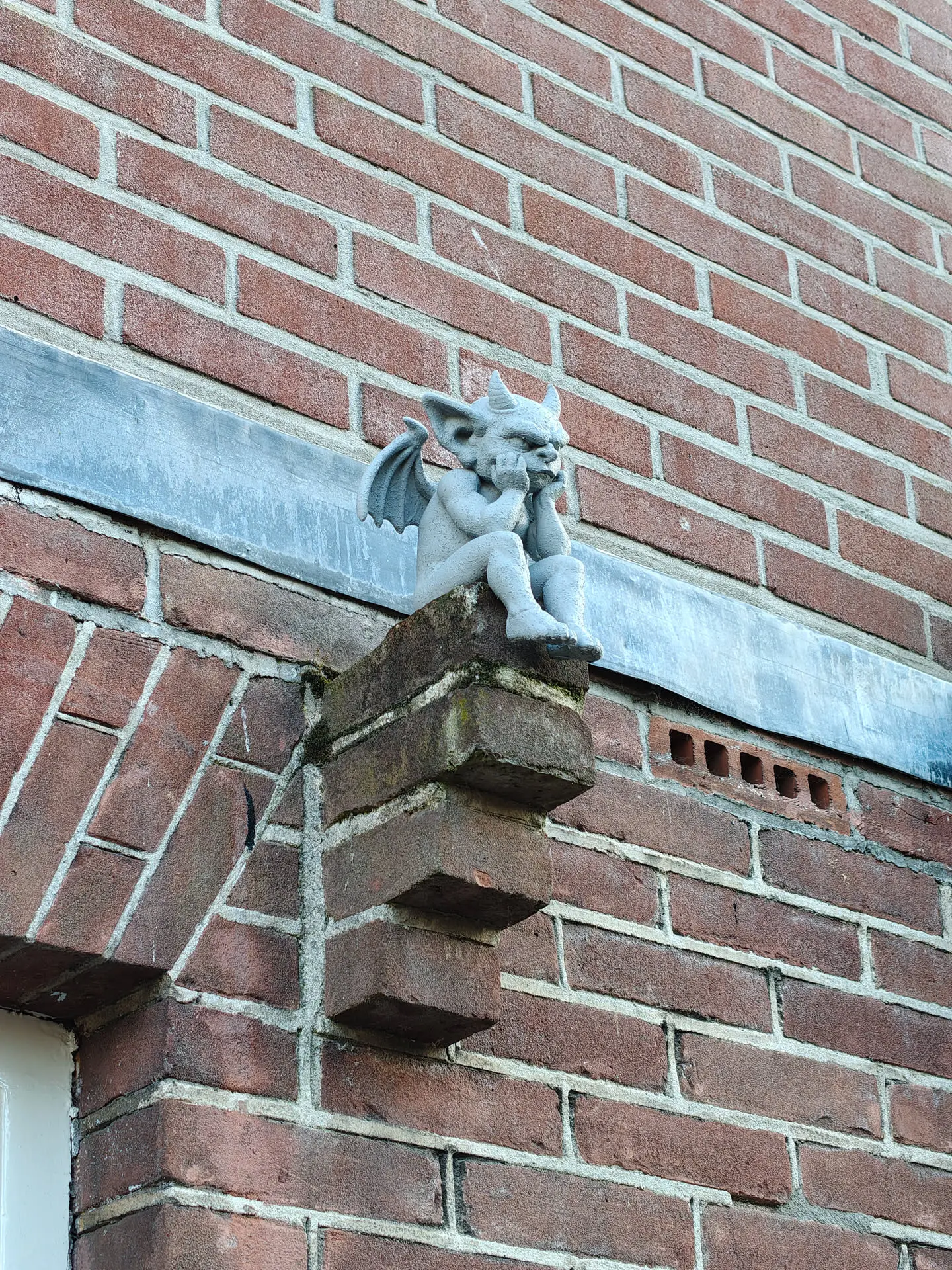
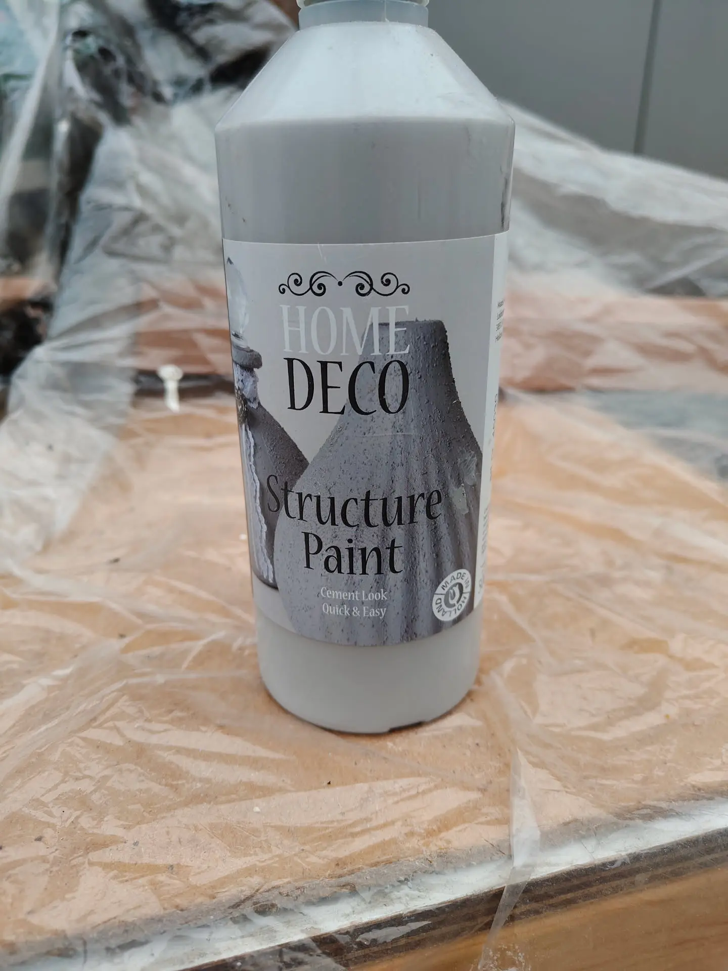
Model by wayneclarke, structure paint is cement look from Havo Holland.
My much used set of tools (old draft I edited)
File managers
Generic tools
Connecting/networking tools
Encryption
Graphical/Photo
Documents/Notekeeping
3D Print/Lasercutting
Coding
Electronics
Ebook / Comic readers
GFX/Video
Music
Virtualisation/Emulation
Password management
API
Beamer
Brewing
Web/App alternatives for bad companies (Mostly own hosted)
Server generic
Unsorted stuff
Window managers (See other post)
Other tools:
Git, tig, xdotool, nmon, ntop, iotop, etc etc (lijstje genereren)
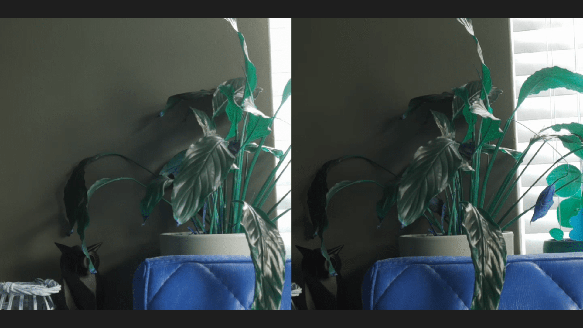
Above a screenshot of a browser screen (Left and Right in fullscreen)
Colors are a little of (codec Red/Blue problem?)
But the setup works!
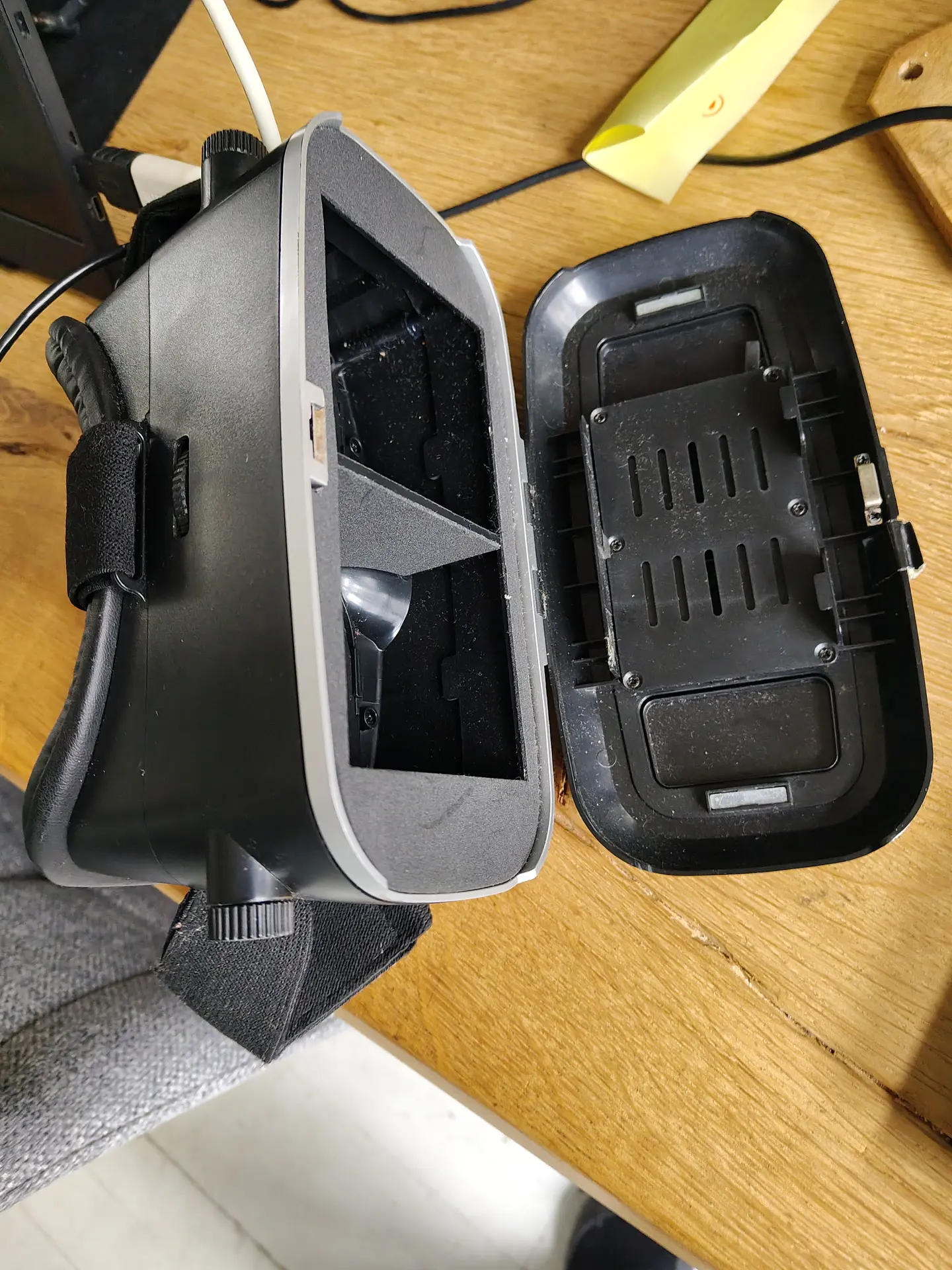
I used a android phone in above setup.
I tried a Quest 2 VR set, but I couldn’t get the browser in full screen mode. (YET)
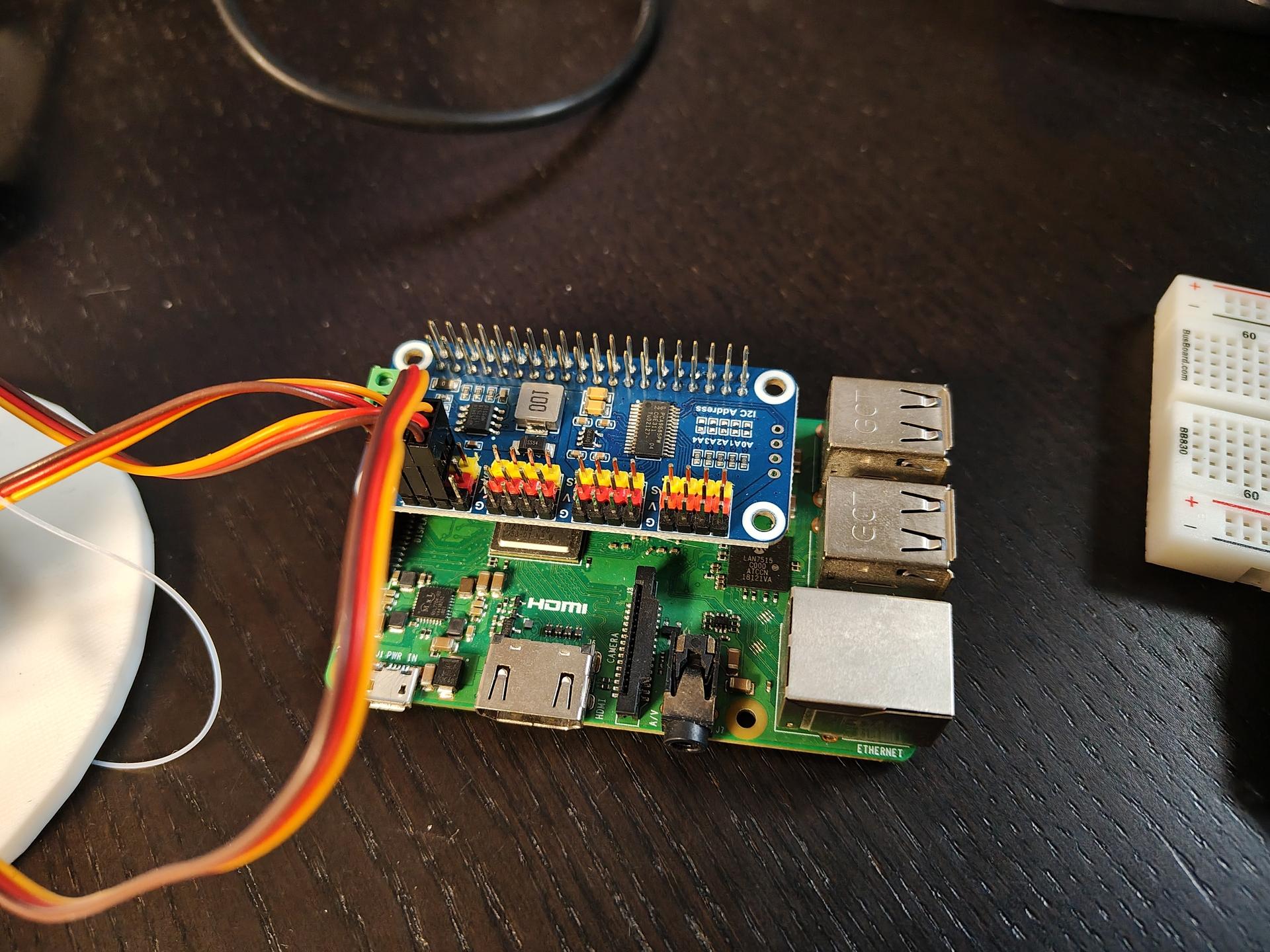
Hardware setup
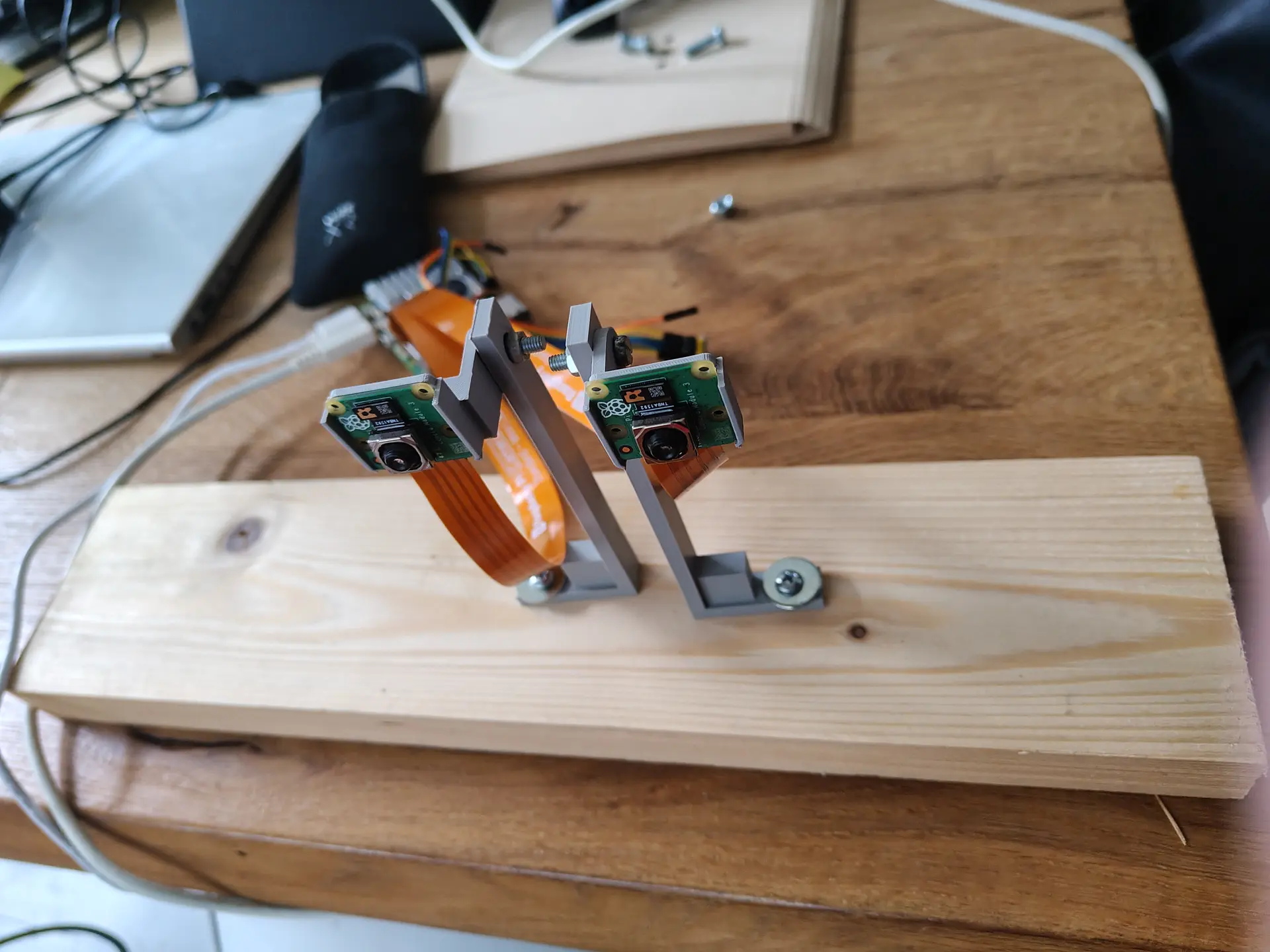
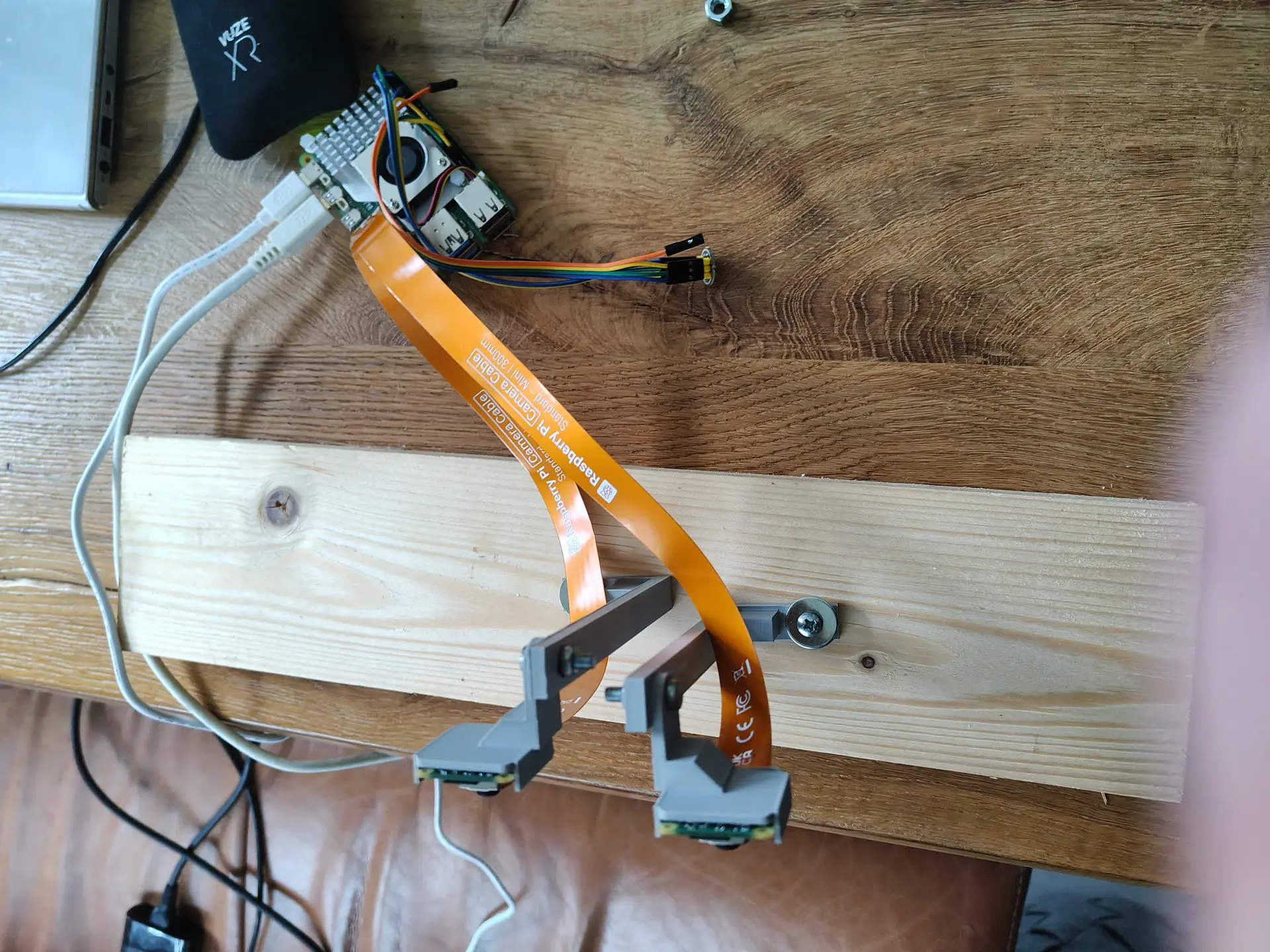
Two Raspberry Pi Camera Modules, connected via the two 4lane-MIPI DSI/CSI connectors.
Manually focussed and using some 3D printed stands on a piece of wood will do for now.
I build a RTSP NGinx proxy to test, which I previously used for OBS. But there was too much latency.
So I used below webrtc setup, with a latency below 80ms.
(I previously did some test using Janus)
CODE:
wget https://github.com/bluenviron/mediamtx/releases/download/v1.16.1/mediamtx_v1.16.1_linux_arm64.tar.gz
tar xzvf media*
cp mediamtx.yml mediamtx.org
NEW mediamtx.yml
webrtc: yes
webrtcAddress: :8889

rtmp: yes
rtmpAddress: :1935

paths:
  dualcam:
    source: publisher
run it
./mediamtx mediamtx.yml
Next make a streamer.
This Python script takes two square camera inputs, merge them side-by-side to one image and pushed the H264 frame to MediaMTX
import numpy as np
from picamera2 import Picamera2
import subprocess
import time

#WIDTH = 1280
WIDTH = 720
HEIGHT = 720
FPS = 30
BITRATE = "2500k"
RTMP_URL = "rtmp://127.0.0.1:1935/dualcam"  # MediaMTX RTMP

# FFmpeg  raw frames / H.264
ffmpeg_cmd = [
    "ffmpeg",
    "-y",
    "-f", "rawvideo",
    "-pix_fmt", "bgr24",
    "-s", f"{WIDTH*2}x{HEIGHT}",
    "-r", str(FPS),
    "-i", "-",
    "-c:v", "libx264",
    "-preset", "ultrafast",
    "-tune", "zerolatency",
    "-b:v", BITRATE,
    "-g", str(FPS),  # keyframe every second
    "-x264-params", "keyint=30:min-keyint=30:no-scenecut=1",
    "-pix_fmt", "yuv420p",
    "-f", "flv",
    RTMP_URL
]


ffmpeg = subprocess.Popen(ffmpeg_cmd, stdin=subprocess.PIPE, bufsize=0)

picam0 = Picamera2(0)
picam1 = Picamera2(1)

cfg0 = picam0.create_video_configuration(
    main={"size": (WIDTH, HEIGHT), "format": "BGR888"}, controls={"FrameRate": FPS}
)
cfg1 = picam1.create_video_configuration(
    main={"size": (WIDTH, HEIGHT), "format": "BGR888"}, controls={"FrameRate": FPS}
)

picam0.configure(cfg0)
picam1.configure(cfg1)

picam0.start()
picam1.start()

print("Streaming to MediaMTX via RTMP...")

try:
    while True:
        f0 = picam1.capture_array()
        f1 = picam0.capture_array()
        combined = np.hstack((f0, f1))
        ffmpeg.stdin.write(combined.tobytes())
        time.sleep(1/FPS)
except KeyboardInterrupt:
    print("Stopping...")
finally:
    picam0.stop()
    picam1.stop()
    ffmpeg.stdin.close()
    ffmpeg.wait()
Open using http://REMOTEIP:8889/dualcam
I’ve got a DIY Bat detector, today I designed and printed a Case for this PCB.
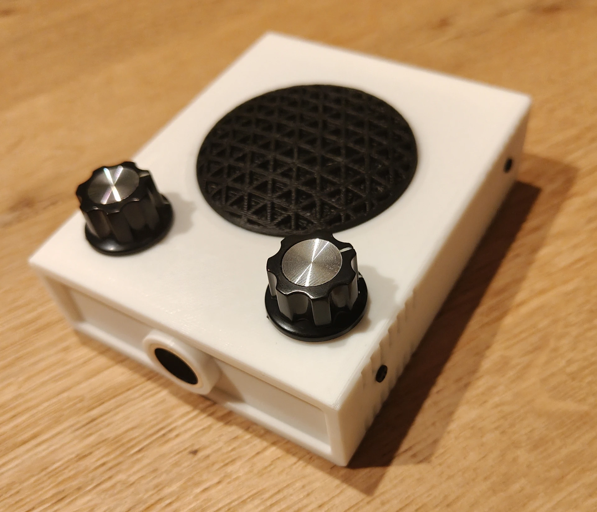
Below a link to the design files
https://media.henriaanstoot.nl/bat-case.zip
Next todo:
These will be available in my shop.
Probably a webpage with measured examples are usefull.
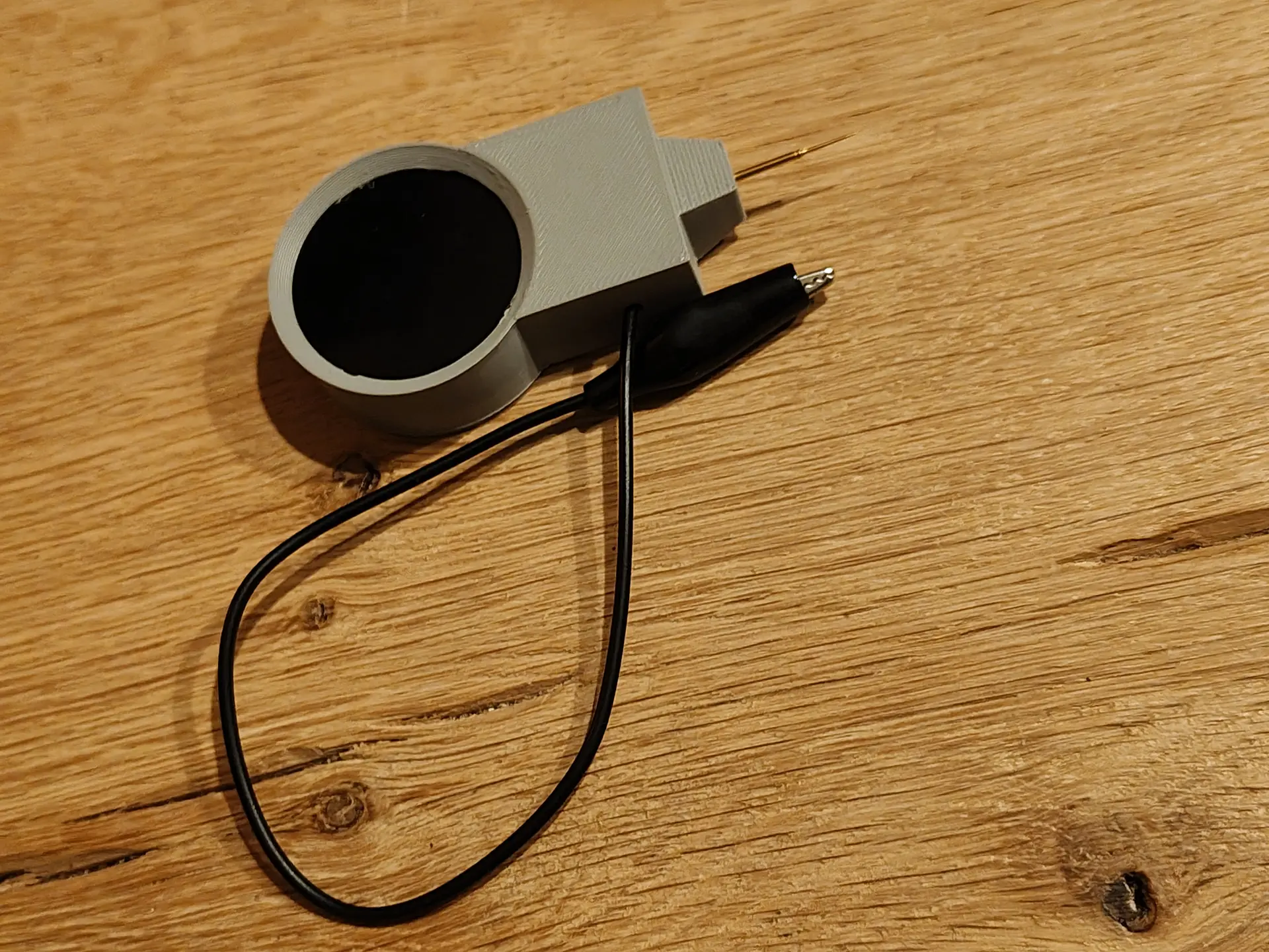
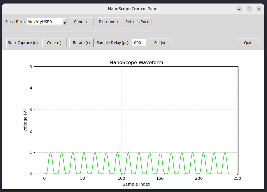
Handheld device to measure voltages and make screenshots using an application.
Control over serial
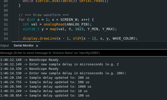
I’m currently working on streaming output.
Below, an example of screenshotting.
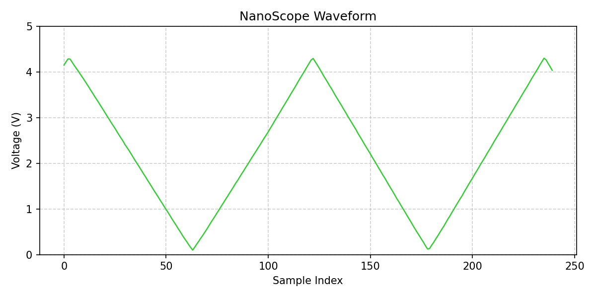
Below, measuring outputs from a NE555 (dutch comments)
I saw a game like this on the WHY2025, I wanted my own version.
Using Twang32, some other hardware and a tweaked sketch, I got this.
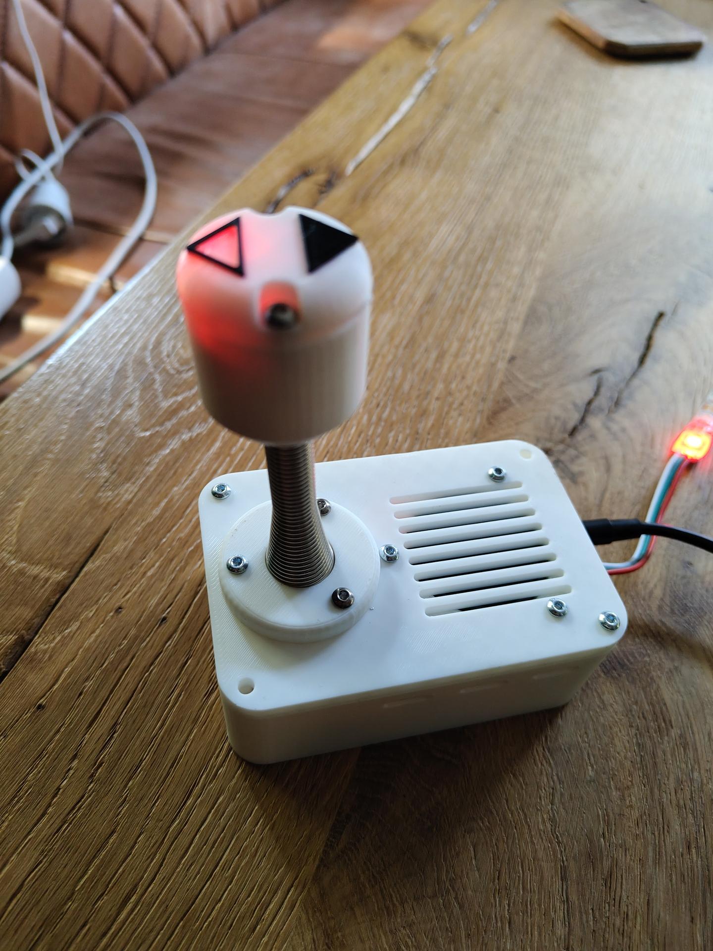
Up = move up
Down = move down
whack the stick to kill red leds (Metal part is a door spring)
(Tilting joystick also works as up/down)
Things changed:
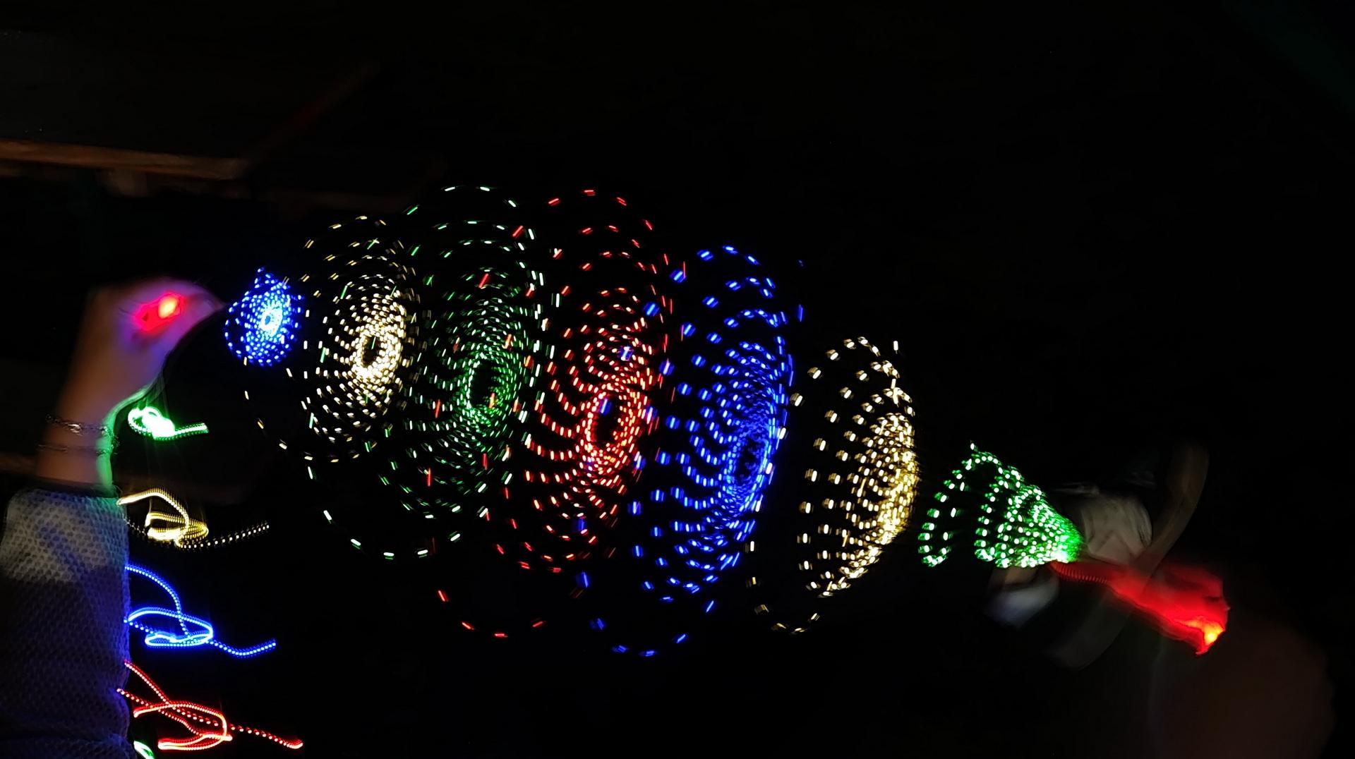
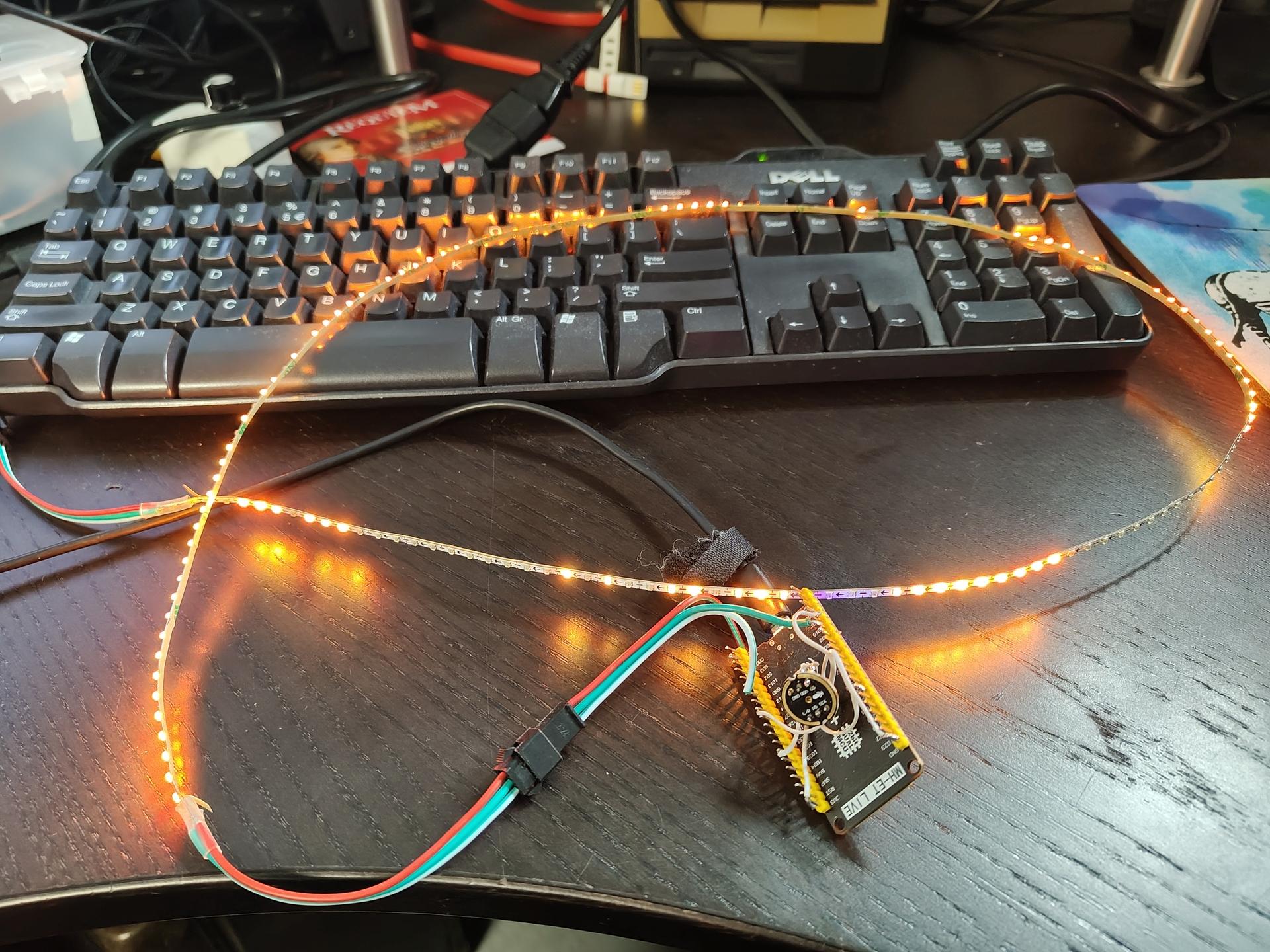
In case of doubt .. MORE LEDS!
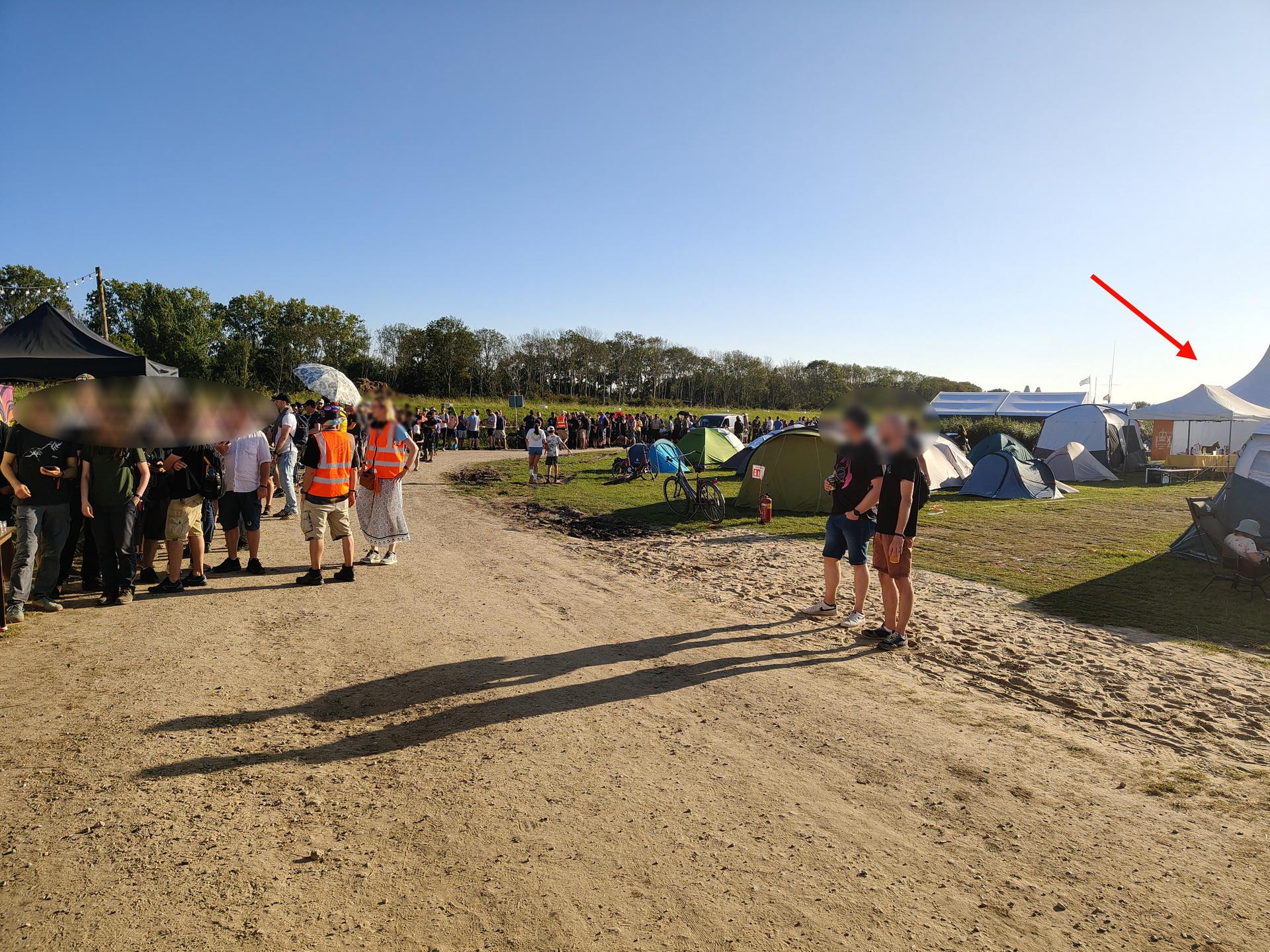
We went to WHY2025 a hackers camp in the Netherlands.
The first time I went was in 1997, with Bigred.
Many followed after that.
Tyrone, Bigred were also there from our old Crew.
Coline joined me several times since 2005.
I joined the Badge team, and was making spacers for the Badges in bulk using my 3D printer.
Also made some fancy cases.
In case of doubt .. more leds!
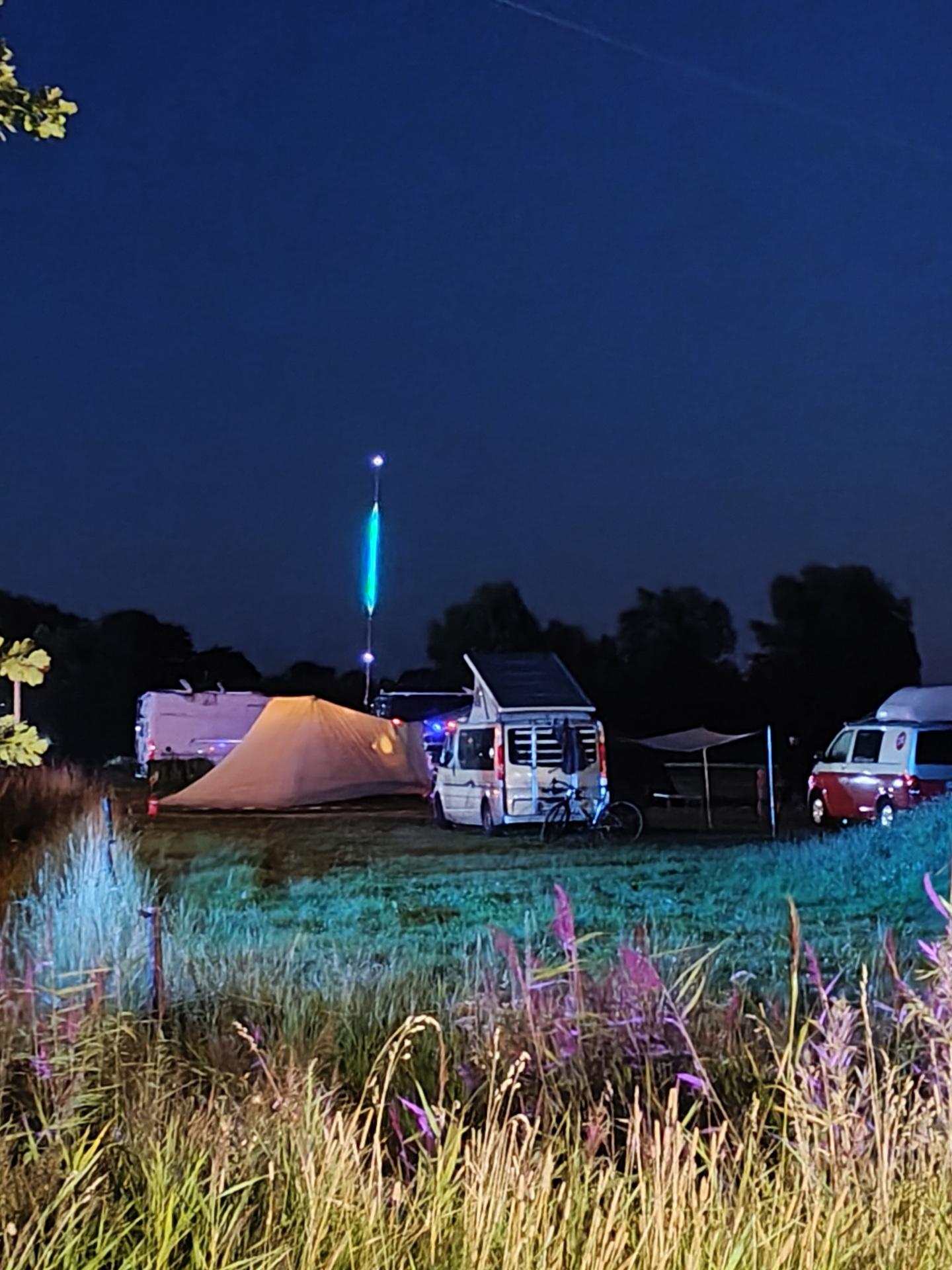
Nice weather, good friends. New friends. Booze. Food and Hacking.
We visited a lot of talks and enjoyed the music. (And fire)
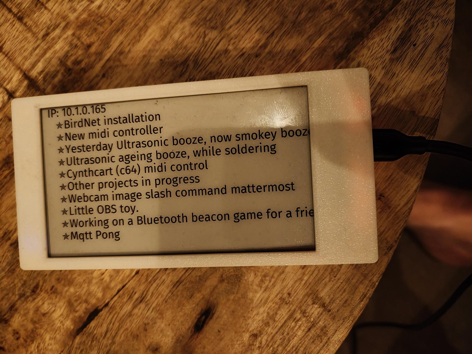
I worked on: RSS feed on a epaper display, Midi monitor and the MQTT Pong website.
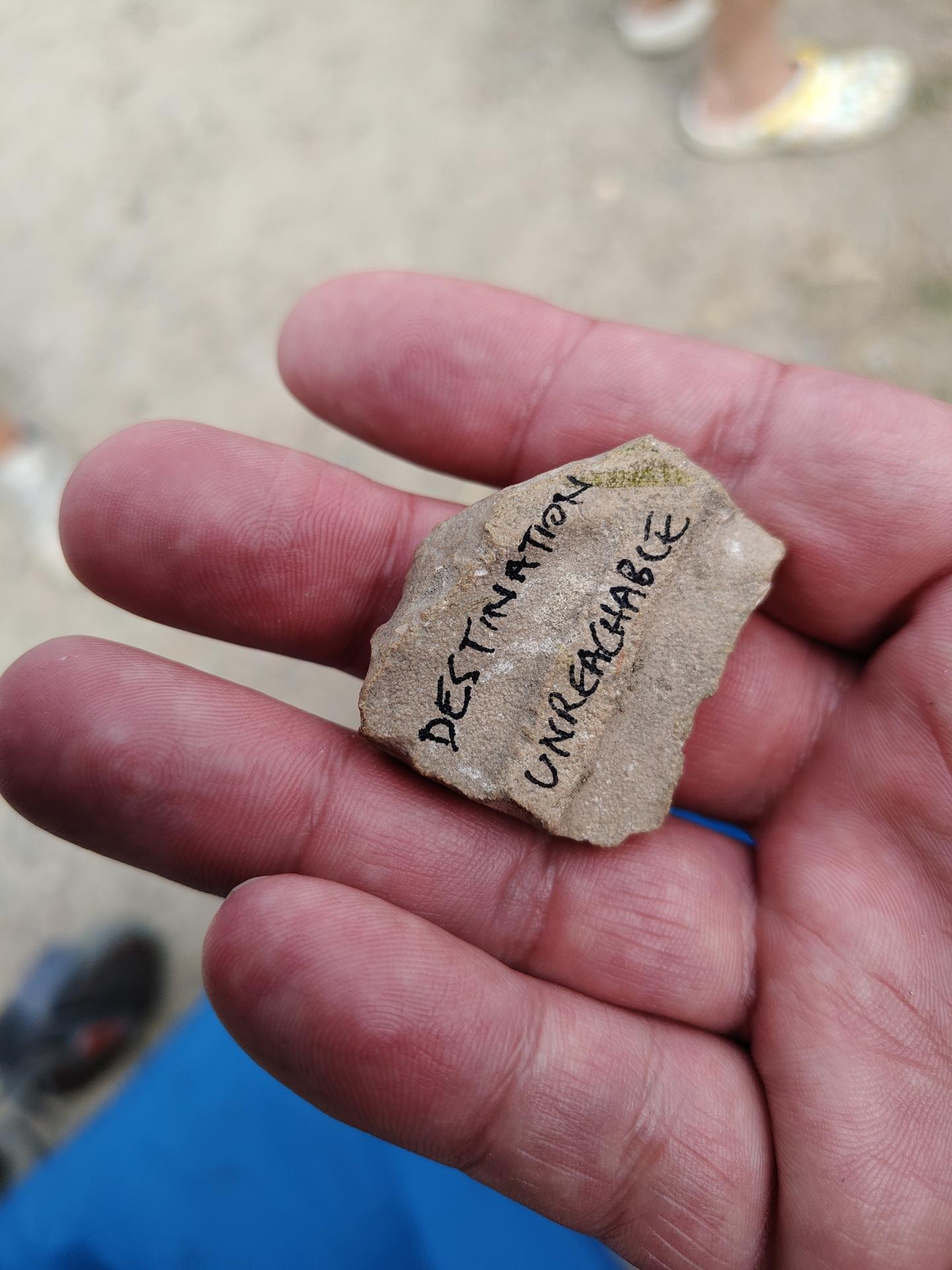
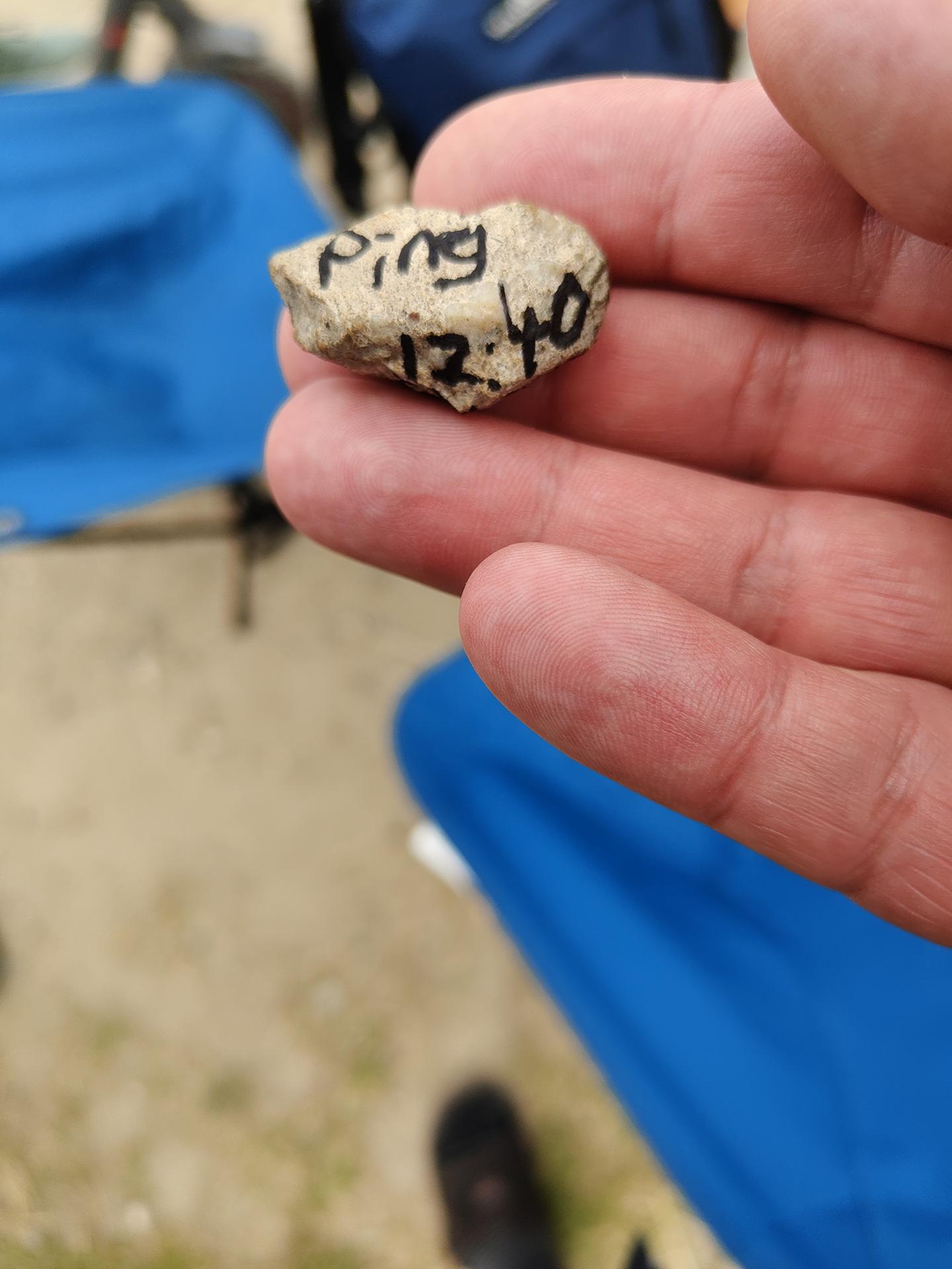
While waiting in line for the Badge:
A stone was passed from behind!
It was a ping request. We passed it forward, and 15 minutes later a TTL time exceeded stone came from the front of the line.
You gotta love those nerds!
The Badge:
This should have got much potential ..
Many misses, much to learn.
Sadly broken:
Our 7M Led string attached to Bigred’s Antenna.
Got some bluetooth beacons in the mail.
The plan is to hide these in the woods, and children have to find them using a scanner device.
Using a ESP32 with bluetooth, using RSSI (strength of signal) I can limit the range of detection.
The order of finding the tags is important, so a hidden tag should not be found when another should be found first.
These tags, hidden in toys, should be placed in a treasure chest.
(In order)
Then lights and sounds should hint the kids that they have successfully completed the mission.
So same detecting but even shorter range ESP is hidden in the Chest.
Some leds or a single blinking one should give hints about the distance of the object.
=== Matching iTags ===
MAC: 5b:08:10:4d:2a:01 | RSSI: -47
MAC: 5b:45:aa:0d:f7:9c | RSSI: -31 #### NEAR
MAC: 5b:88:fc:fc:e8:a9 | RSSI: -94 #### FAR AWAY
MAC: 5b:8b:00:00:1d:40 | RSSI: -66
Some test code:
#include <BLEDevice.h>
#include <BLEUtils.h>
#include <BLEScan.h>
#include <BLEAdvertisedDevice.h>

int scanTime = 5; // seconds
BLEScan* pBLEScan;

void setup() {
  Serial.begin(115200);
  Serial.println("Starting BLE scan...");

  BLEDevice::init("");
  pBLEScan = BLEDevice::getScan();
  pBLEScan->setActiveScan(true);
  pBLEScan->setInterval(100);
  pBLEScan->setWindow(99);
}

void loop() {
  BLEScanResults results = *pBLEScan->start(scanTime, false);
  Serial.println("=== Matching iTags ===");

  for (int i = 0; i < results.getCount(); i++) {
    BLEAdvertisedDevice device = results.getDevice(i);
    String mac = device.getAddress().toString();

    if (mac.startsWith("5b:")) {
      Serial.print("MAC: ");
      Serial.print(mac);
      Serial.print(" | RSSI: ");
      Serial.println(device.getRSSI());
    }
  }

  Serial.println("======================");
  pBLEScan->clearResults();
  delay(2000);
}
I like animatronics.
In the past, I made animatronics using :
Windscreen wipers, Servo controllers and stepper motors.
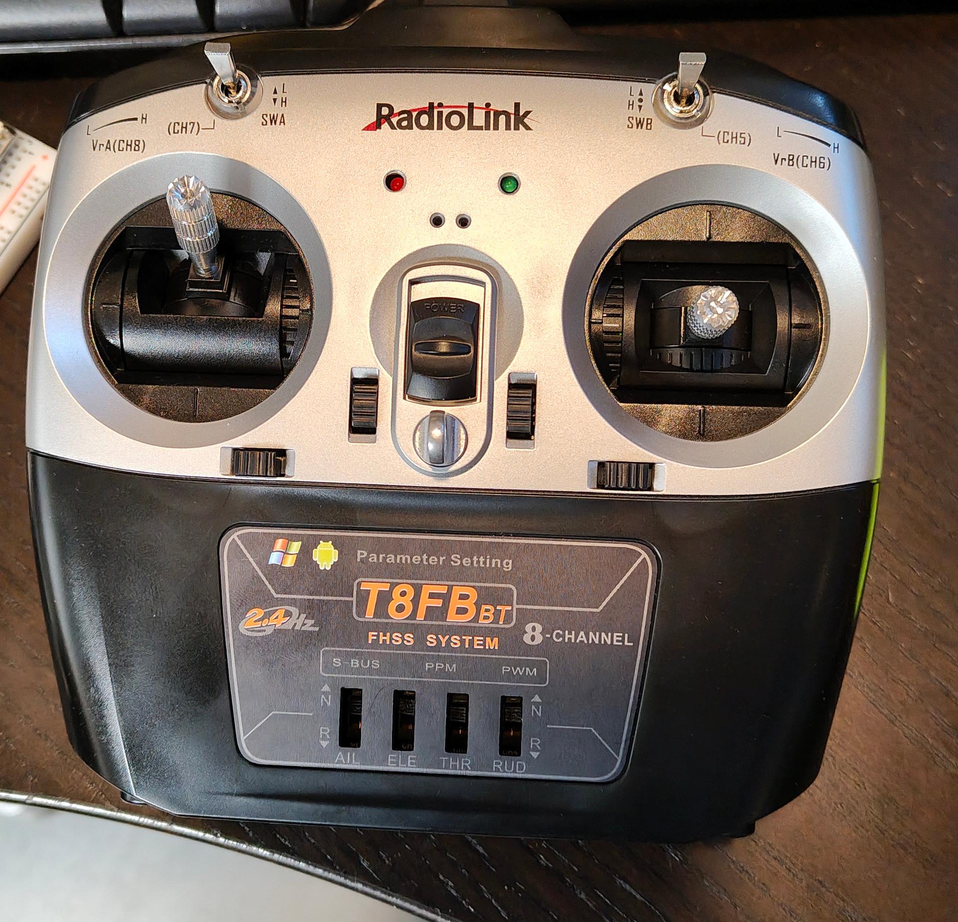
I bought a new controller with an 8 channel receiver. Now I can manually control and test setups.
I altered and 3D printed this model from Will Cogley
Now I have to make this more programmable, python on a RPi should do it.
Planning to use a 360 degrees lidar, so the eyes can follow you around.
I got some other new stuff in also:
Some 360 degrees servo’s and a mini led strip which a connected to a WLED with digital I2S microphone.
While working on my clients projects, I’ve been busy with other Fun stuff.
All will be posted more about soon