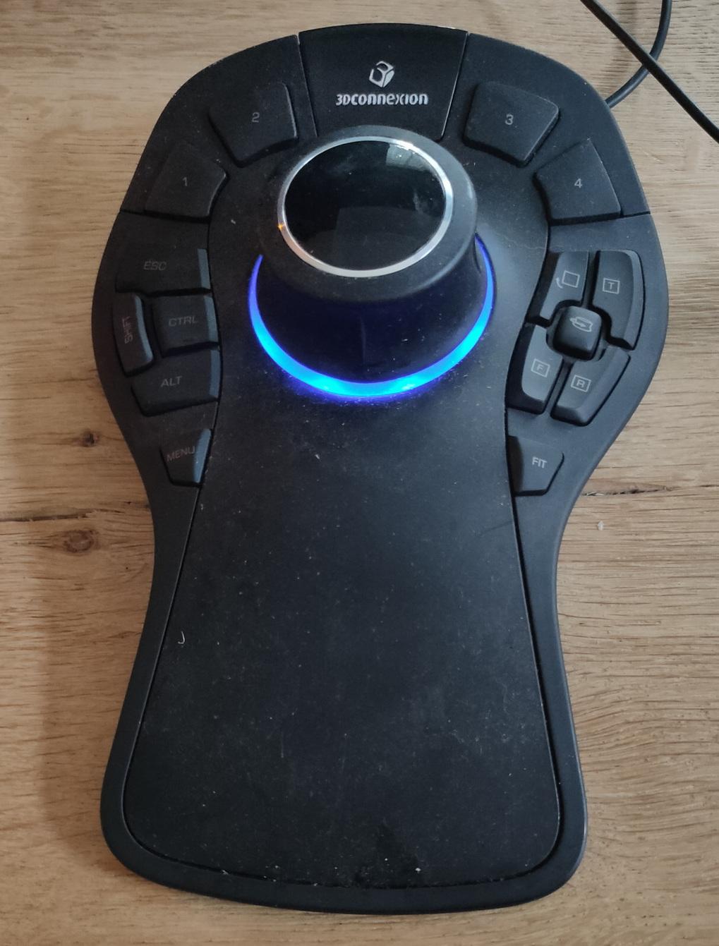
Running into some Ubuntu machines with keyboard mouse problems after upgrading to 24.04
fix:
apt get install xserver-xorg-input-synaptics
apt get install xserver-xorg-input-all
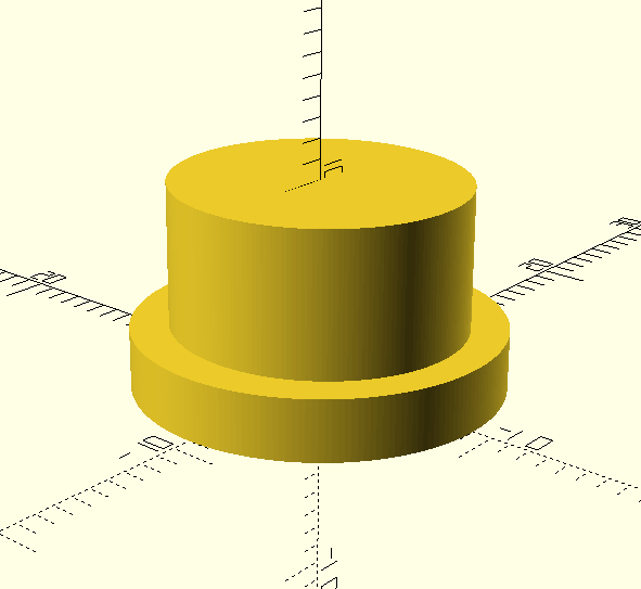
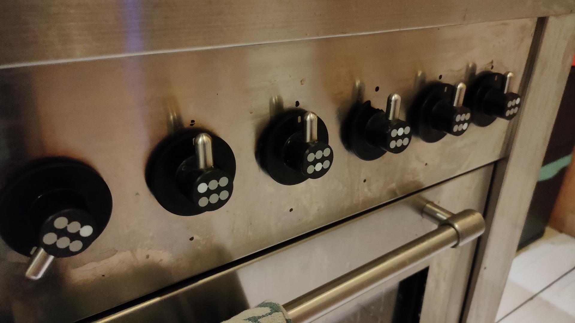
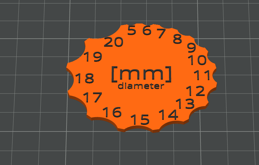
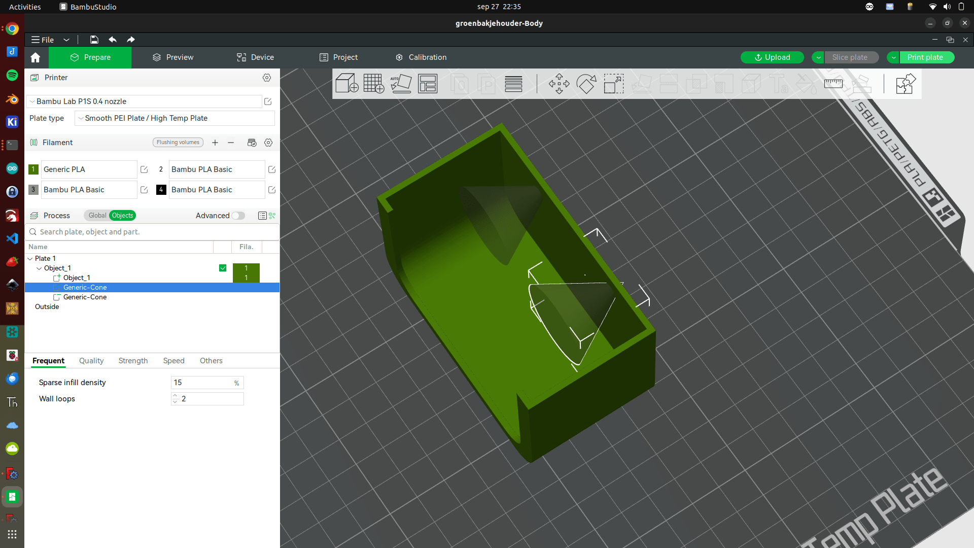
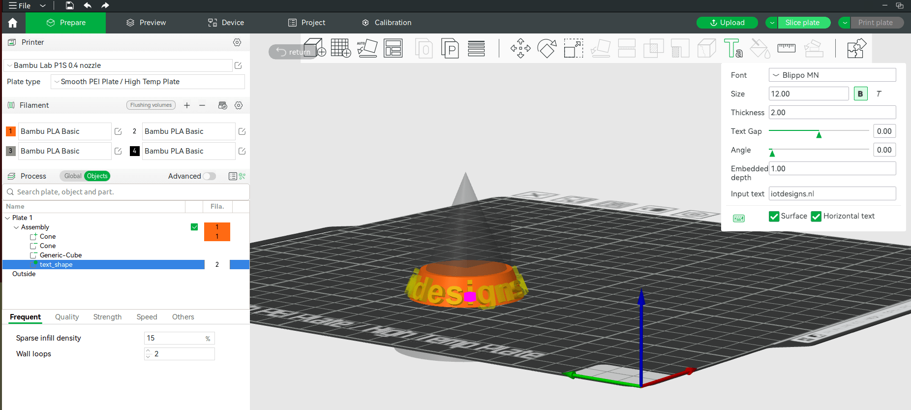
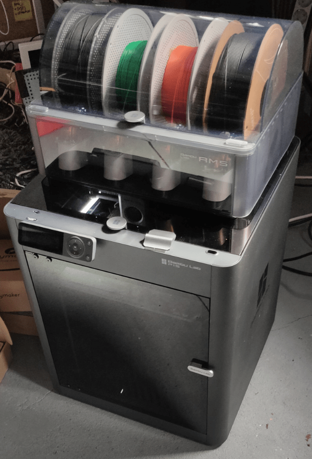
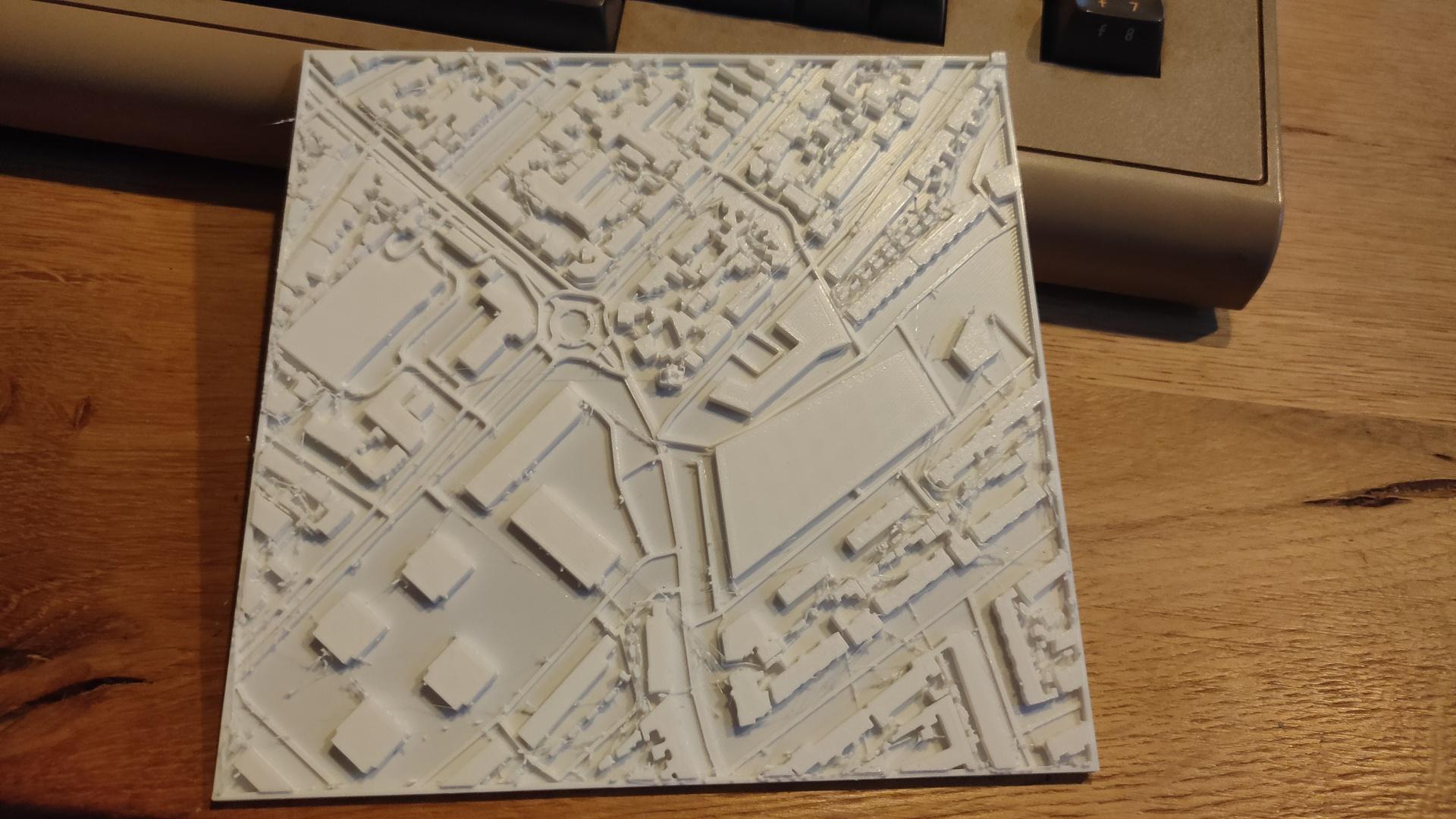
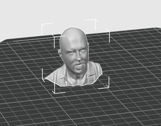
3D printing some test models generated with AI from a photo to make some boardgame pieces.
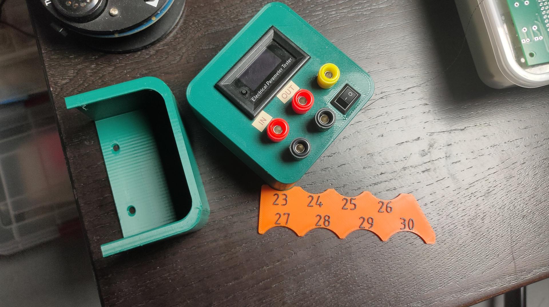
Meanwhile, I am testing big motor controllers for a new client.
Last week I was at a friend’s place, time to make a launcher creator in bash
#!/bin/bash
#
if [ $# -lt 2 ]; then
	echo "createlauncher.sh name (path/bin) path/name"
    exit 1
fi


cat << EOF > /tmp/$1
[Desktop Entry]
Type=Application
Terminal=false
Name=$1
Icon=~/bin/icon/$1.png
Exec=$2 $3
EOF

cp /tmp/$1  ~/.local/share/applications/$1.desktop
update-desktop-database
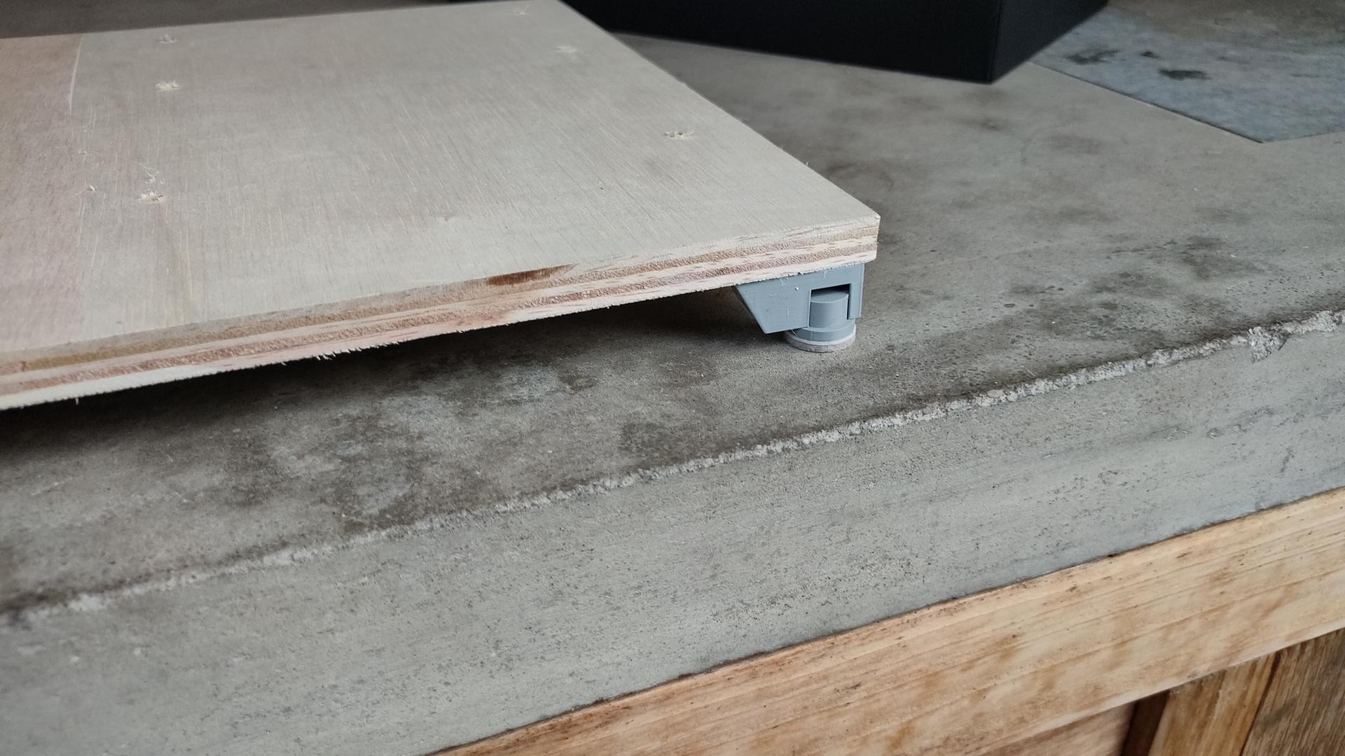
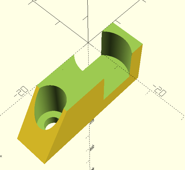
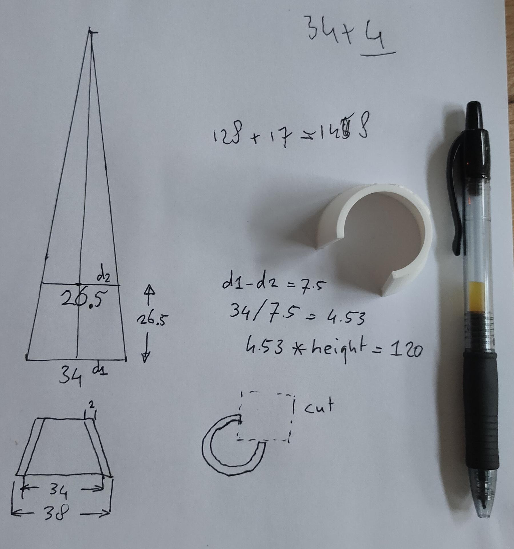
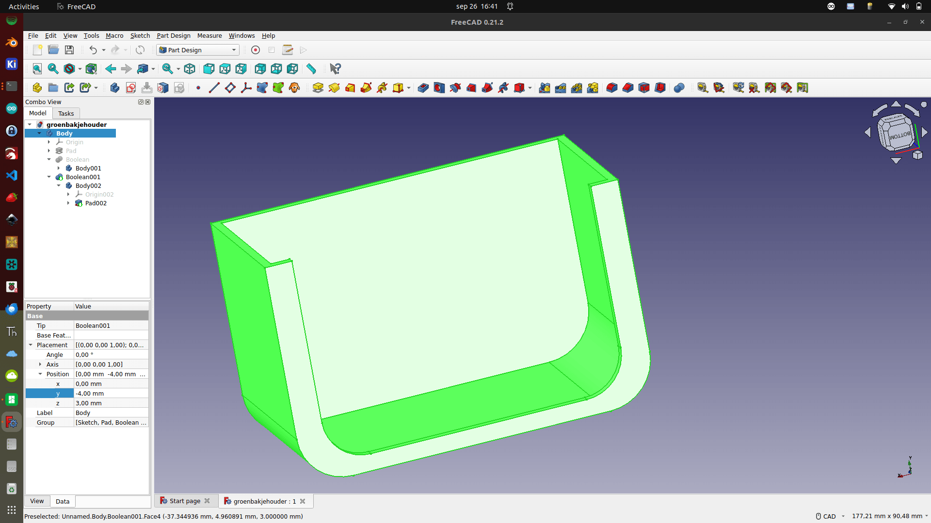
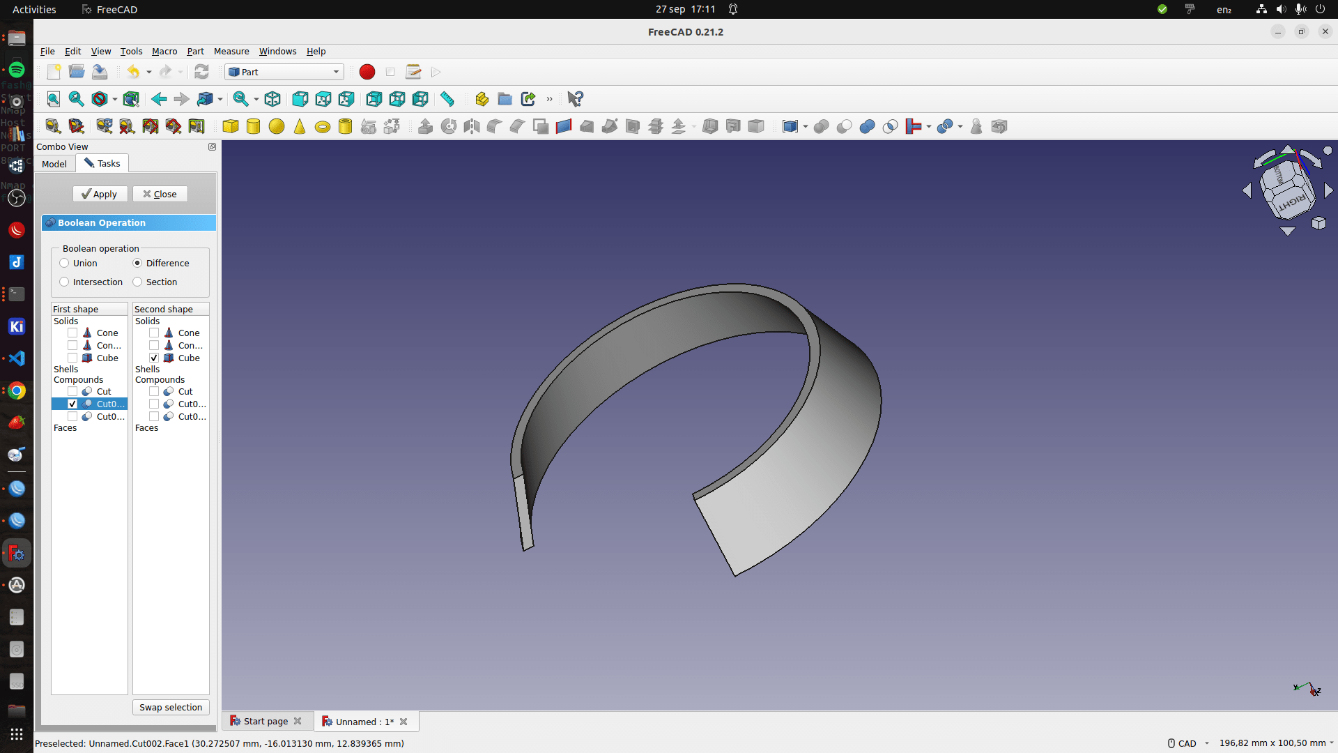
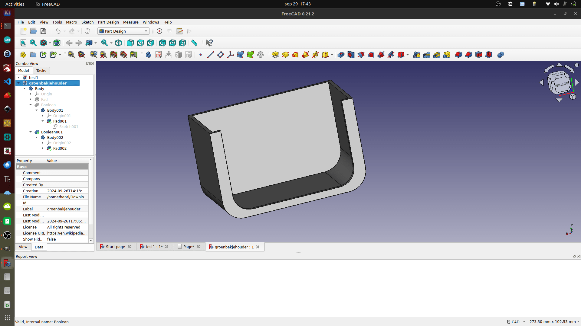
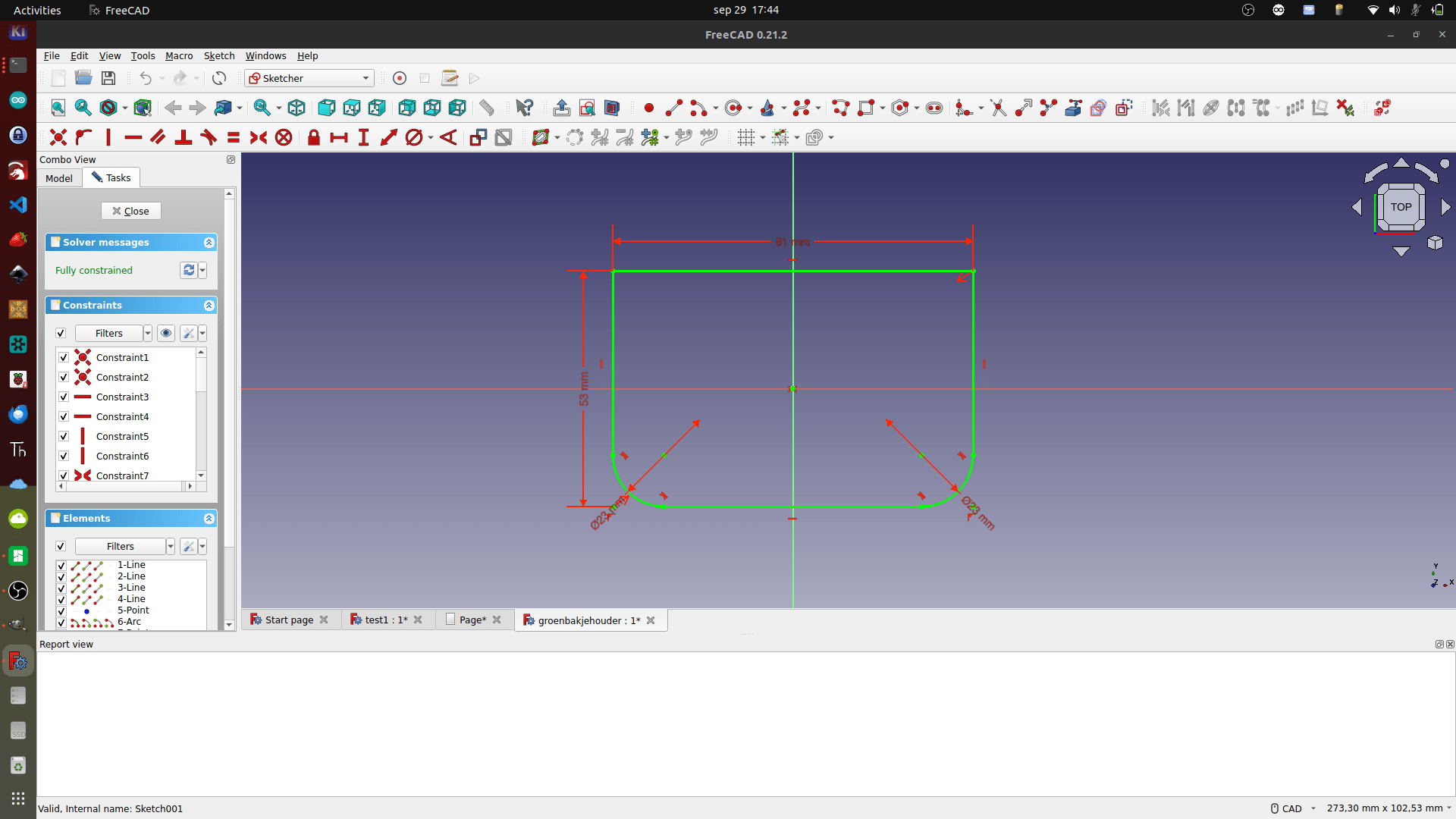
Made a cable holder in my lab (Already modded)
Can be folded upwards.
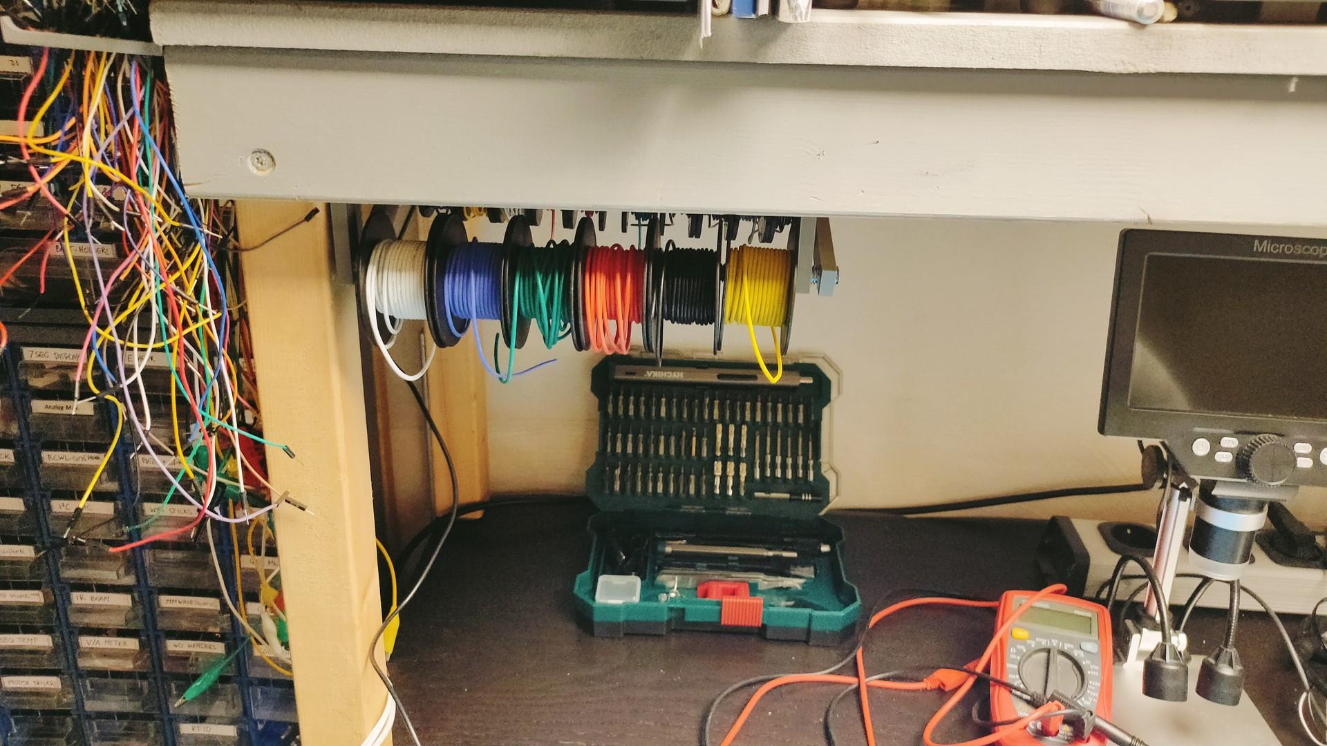
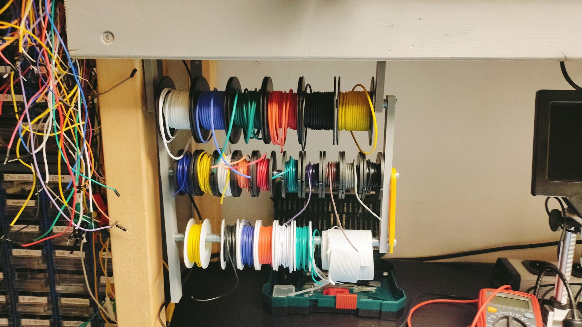
Did a lot of work in my new lab/workshop.
Got some cool new tools in. Post later
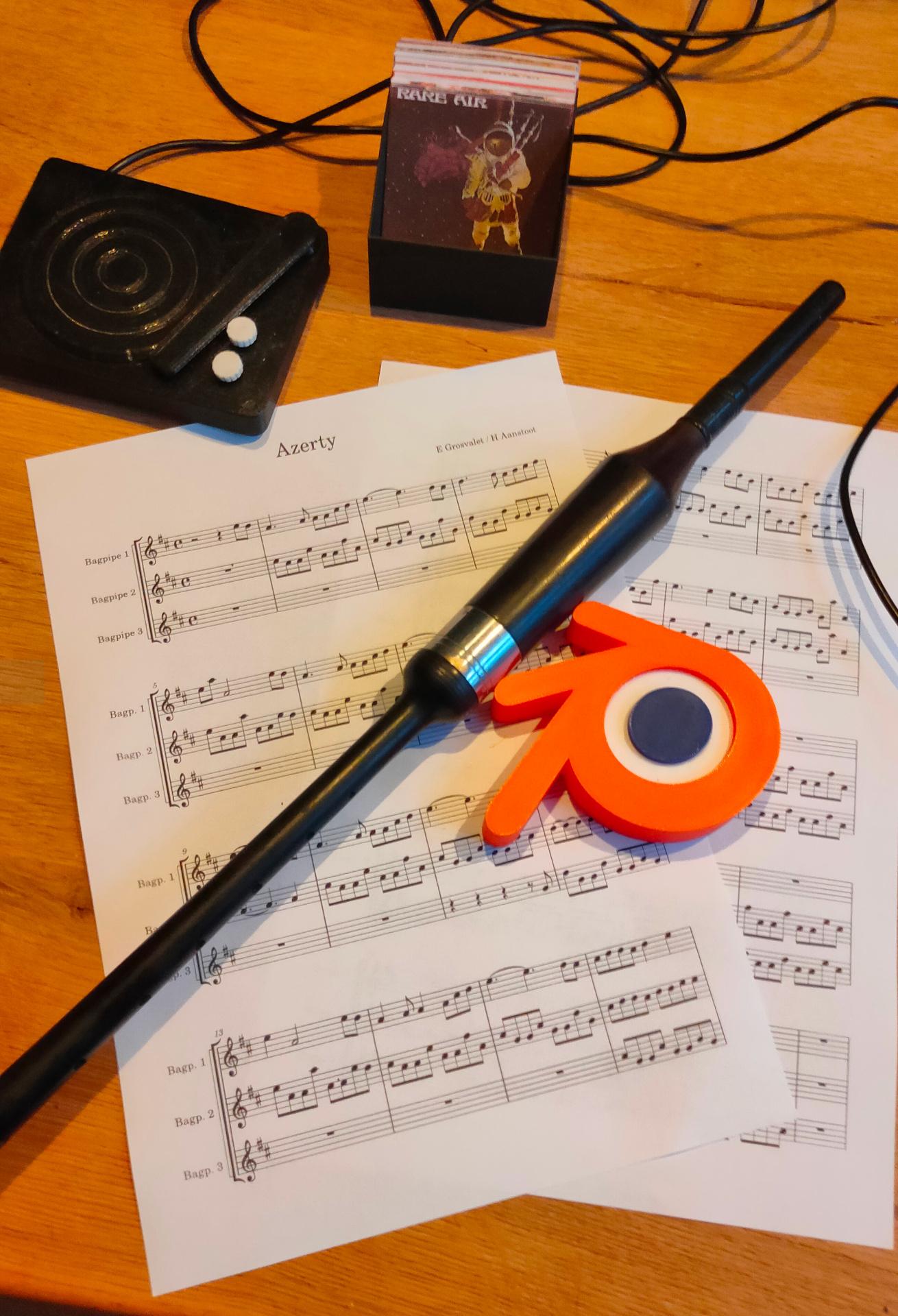
Also working on a new arrangement for a bagpipe tune.