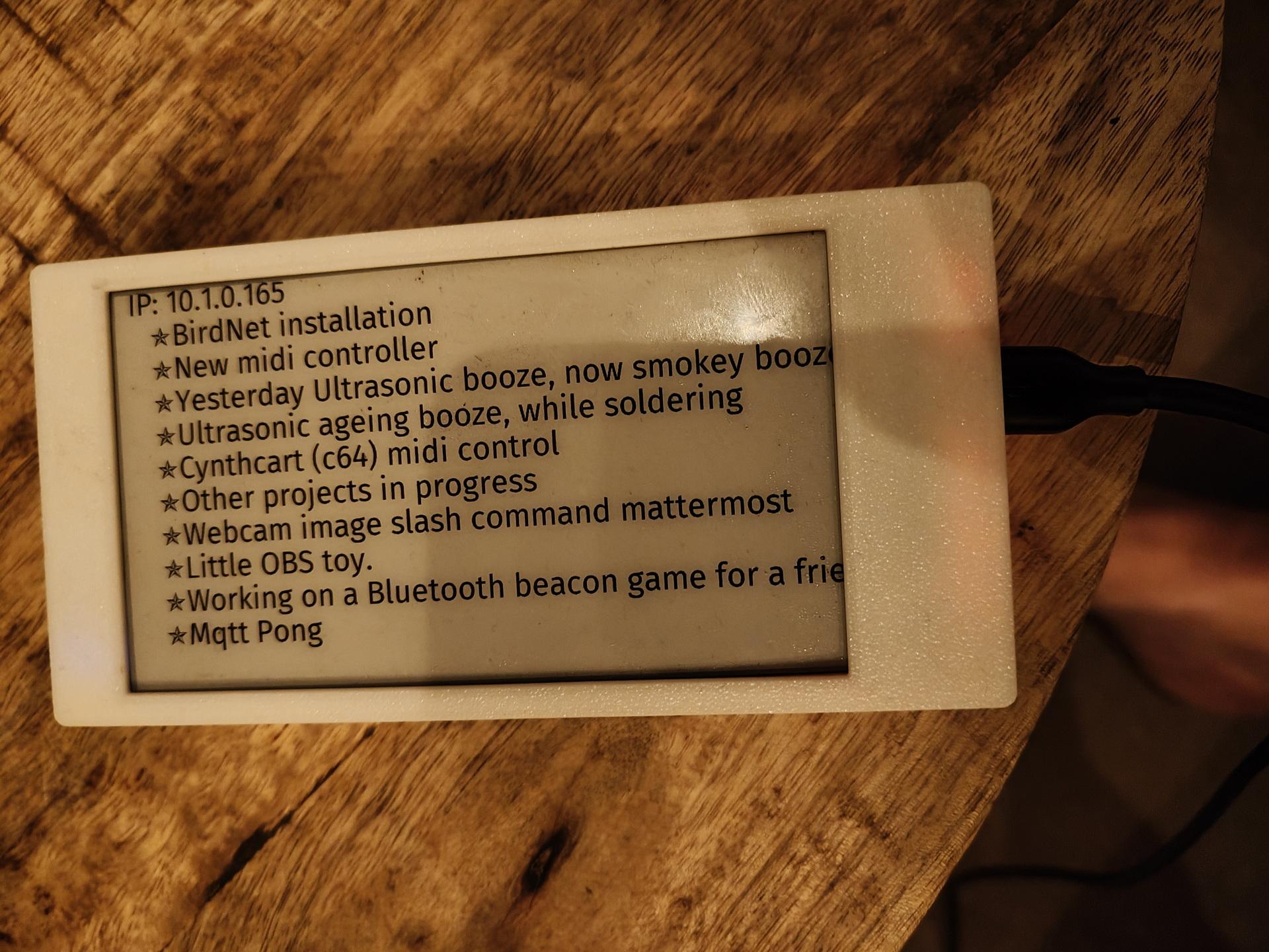
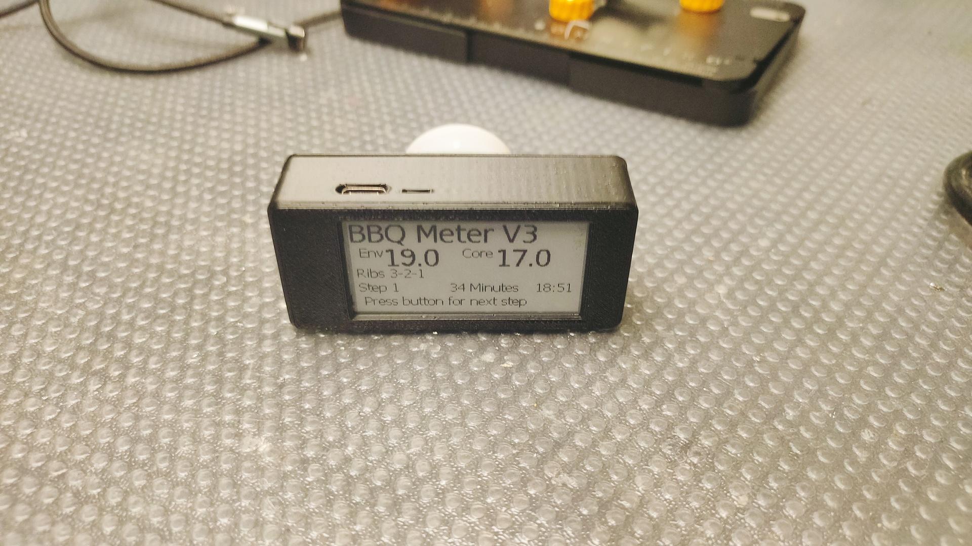
Tag Archives: programming

I tried to recreate an optical illusion

My friend Tyrone posted something he recorded from TV.
It was an illusion, using rotated images.

The effect is that it seems that the card is rotating at different speeds, when pressing the s (show/unshow) key, you see the card rotating at the same speed as before.

So I wanted to try to recreate this using python.
The effect is there, but a little less.
What can I improve?

Mine:

Around the 30 seconds mark I disable the background, you’ll see the card rotating as before.

Original:

Better version, larger and using s key to toggle water off, to see the card rotating

import pygame
import math

# 20240409 added s to toggle 

pygame.init()
screen = pygame.display.set_mode((1600, 900))
clock = pygame.time.Clock()

def blitRotate(surf, image, pos, originPos, angle):

    image_rect = image.get_rect(topleft = (pos[0] - originPos[0], pos[1]-originPos[1]))
    offset_center_to_pivot = pygame.math.Vector2(pos) - image_rect.center
    rotated_offset = offset_center_to_pivot.rotate(-angle)
    rotated_image_center = (pos[0] - rotated_offset.x, pos[1] - rotated_offset.y)
    rotated_image = pygame.transform.rotate(image, angle)
    rotated_image_rect = rotated_image.get_rect(center = rotated_image_center)
    surf.blit(rotated_image, rotated_image_rect)

try:
    image = pygame.image.load('cards.png').convert_alpha()
    image2 = pygame.image.load('clear+sea+water-2048x2048.png').convert_alpha()
except:
    text = pygame.font.SysFont('Times New Roman', 50).render('imagemissing', False, (255, 255, 0))
    image = pygame.Surface((text.get_width()+1, text.get_height()+1))
    image2 = image
    image.blit(text, (1, 1))

w, h = image.get_size()
angle = 0
angle2 = 0
done = False
while not done:
    clock.tick(60)
    for event in pygame.event.get():
        if event.type == pygame.QUIT:
            done = True

    pos = (screen.get_width()/2, screen.get_height()/2)
    
    screen.fill(0)
    keys = pygame.key.get_pressed()
    if (not keys[pygame.K_s]):
        blitRotate(screen, image2, pos, (900, 900), angle2)
    blitRotate(screen, image, pos, (w/2, h/2), angle)
    angle += 1
    angle2 += math.sin(math.radians(angle))
    pygame.display.flip()
    
pygame.quit()
exit()

64×64 Matrixrgb plus Conway’s Game of Life

Yesterday I got this nice led matrix I mentioned before.

I wanted to control this display using Circuit Python and a Raspberry Pico.

Pico  Matrix
GP0   R1
GP1   G1
GP2   B1
GP3   R2
GP4   G2
GP5   B2
GP6   A
GP7   B
GP8   C
GP9   D
GP10  Clock
GP11  E
GP12  Latch
GP13  Output Enable

GND   GND ( I did both )

I installed Circuit Python and the following libraries.

adafruit_imageload, adafruit_display_text.label (the rest was already in the uf2 firmware.)
(Check this link : https://circuitpython.org/board/raspberry_pi_pico/ )
I could not install the Wifi uf2 file, then I got a out of storage space when installing the adafruit libraries.

importing libaries and init display

import board, digitalio, busio, time, displayio, rgbmatrix, framebufferio
import adafruit_imageload, terminalio, random
import adafruit_display_text.label

displayio.release_displays()
matrix = rgbmatrix.RGBMatrix(
    width=64, bit_depth=2, height=64,
    rgb_pins=[board.GP0, board.GP1, board.GP2, board.GP3, board.GP4, board.GP5],
    addr_pins=[board.GP6, board.GP7, board.GP8, board.GP9, board.GP11],
    clock_pin=board.GP10, latch_pin=board.GP12, output_enable_pin=board.GP13)
display = framebufferio.FramebufferDisplay(matrix)

I became interested in Conway’s “Game of Life”, in 1983. Reading a article in the Dutch Magazine Kijk.

The Game of Life, also known simply as Life, is a cellular automaton devised by the British mathematician John Horton Conway in 1970. It is a zero-player game, meaning that its evolution is determined by its initial state, requiring no further input. One interacts with the Game of Life by creating an initial configuration and observing how it evolves. It is Turing complete and can simulate a universal constructor or any other Turing machine.

https://en.wikipedia.org/wiki/Conway%27s_Game_of_Life

I found these on my server. Bad quality, I know. Scanned these many years ago.

The rules are:

  1. Any live cell with fewer than two live neighbours dies, as if by underpopulation.
  2. Any live cell with two or three live neighbours lives on to the next generation.
  3. Any live cell with more than three live neighbours dies, as if by overpopulation.
  4. Any dead cell with exactly three live neighbours becomes a live cell, as if by reproduction.

When playing with the Basic code as a kid, I wanted to try if it was possible to make a 3D version of this.

I came up with the following rules:

  1. Birth : 4 alive neighbours needed
  2. Survive : 5 or 6 neighbours
  3. Dead : below 4 and over 6

I think there should be a BBC Acorn basic version I wrote somewhere.

Back to the display

Greetings to my friends
Game of Life starting with my Logo plus a glider
A single Gosper‘s glider gun creating gliders

Code for the glider gun

    conway_data = [
        b'                        +           ',
        b'                      + +           ',
        b'            ++      ++            ++',
        b'           +   +    ++            ++',
        b'++        +     +   ++              ',
        b'++        +   + ++    + +           ',
        b'          +     +       +           ',
        b'           +   +                    ',
        b'            ++                      ',
    ]

Next todo:

  • Line functions
  • Design a Chip tune hardware add-on
  • Make a Game of Life start situation selector
  • Make a new Maze game!

LCD matrix idea’s

In previous post I was talking about an esp32 with display for demo’s.
But my friend Erik mentioned a cheap LCD matrix from Ali.

What about creating something cool with that!

My Maze project would look amazing on this!
I can draw walls now!

Or I could make a cool audio visualiser, like the posted WLED version

Ehh .. not posted (well I can’t post everything)

What about a game of life display?
Using a web interface for inputting the start situation of the cells

Conway’s Game of Life is a cellular automaton. It consists of a grid of cells, each of which can be alive or dead. The state of each cell evolves based on simple rules: any live cell with fewer than two live neighbours dies (underpopulation), any live cell with two or three live neighbours survives, and any live cell with more than three live neighbours dies (overpopulation). Additionally, any dead cell with exactly three live neighbours becomes alive (reproduction). This simple set of rules can lead to complex patterns and behaviours.

But back to the demo …

What about a 6502 with 64×64 pixel display!

What would be needed?

  • 6502, with rom and ram
  • Some IO chip, don’t know which one yet
  • The 64×64 pixel matrix
  • A sound solution (simple chip tune player)
  • 3D printed enclosure

Using some libraries and a framework setup, maybe there is a way to make a cool and cheap demo machine

Do you have any suggestions ideas?
Comment or email me!

Album player using old CD Cover site.

In the past, I made an overview of CDs I own, and which CDs I was missing from my top artists.

Today I wanted to have a little test using above code and some additional script to get a little website which enables me to quick start playing an album using LMS.

Exporting the album database in Linux:

sqlite3 /var/lib/squeezeboxserver/cache/library.db ".dump albums" > /mnt/www/albums-test.dump

grep -i culture /mnt/private/albums
INSERT INTO "albums" VALUES(16872,'Bothy Culture','BOTHY CULTURE','BOTHY CULTURE',NULL,0,0,NULL,NULL,NULL,NULL,NULL,NULL,NULL,18957,NULL);

So, 16872 is the needed album ID.

To start playing this (adhoc), I used the below command.

curl "http://IP-OF-MY-LMS-SERVER:9000/anyurl?p0=playlistcontrol&p1=album_id:16872&p2=cmd:load&player=12:23:34:45:56:67"

Player=12:23:34:45:56:67 is the mac address from a squeezebox player.

I wrote some additional PHP code in my original CD Cover site, and got this working.

I think I will rewrite the code using python to get a more flexible generator.

Left the LMS player, right the cover website. (Clicking 3 covers to change albums)

C64Pico Follow-up

Soldering almost done, except for the space bar all tactile buttons in place.

Using my USBasp programmer I tried to program the Atmega328pb.

Same one I used for:

I first needed to implement some udev rules to get the rights for the reader correct.

#/etc/udev/rules.d/99-usbasp.rules
SUBSYSTEM=="usb", ATTRS{idVendor}=="16c0", ATTRS{idProduct}=="05dc", GROUP="dialout"

Next I tried to burn a bootloader.

Well, not as planned, back to the drawing board.

Hopefully I compiled at least the Pico part correctly.

Three channel mixer for ay-3-8910 is almost done.

At the back the 8 pin single channel lm368 amplifier.
At the front the 3 channel setup.
I still have to tweak the resistors, and potmeters.
Then I can make a permanent PCB, and figure out the connections to the 6502.

At the moment, the Arduino Nano is playing some real sound samples by using the registers of the sound chip.
The music is being played by sending the register dumps directly to the chip.

Much like i’ve been using SID register dumps to play songs in another project.

This is version 0.1 .. do not use.
If its wrong, or can do better please mail me.
Oh it needs a 1k resistor from the 20K’s to ground I think.

PL/M-86

I’ve posted in the past something about pl/m.
Today i got this running again in a dosbox.

The PL/M programming language (an acronym of Programming Language for Microcomputers) is a high-level language conceived and developed by Gary Kildall in 1973 for Intel’s microprocessors.

A link to information about Gary, and ebook (pdf) he wrote.

We learned to program PL/M at school (MTS)

Below the compiler and lib files

https://media.henriaanstoot.nl/plm86.zip

Example program Tic Tac Toe I wrote in 1990

Compiling a PLM source code

PLM86 PROGRAM.PLM
LINK86 PROGRAM.OBJ, PLM\DOSLIBS.LIB, PLM\UTILS.LIB TO %1.LNK INITCODE
LINK PROGRAM.LNK;;;

Tic Tac Toe in PLM

bke:do;
/*DOEL:                                              */
/*Dit programma is boter kaas en eieren voor twee    */
/*spelers, er wordt gecontroleerd of iemand gewonnen */
/*heeft. (Je speelt niet tegen de computer)          */
/*UPDATE:12/2/90,15/2/90,18/2/90  RELDATE:19/2/90    */
/*PROGRAMMER:H.M.Aanstoot                            */
/*UPDATE 5/3/90 1:13:23                              */
/*De volgende 4 regels zorgen ervoor dat de compiler */
/*de PLM  DOS,UTIL routines die op disk staan        */
/*meestuurt naar de linker                           */
/* bla bla 2de versie met STRINGS!! eindelijk gelukt */

$include(plm\doslibs.inc)
$include(plm\doslibs.dcl)
$include(plm\utils.dcl)
dcl naam(3)           pointer;
dcl plaats(9)         word;
dcl teken(2)          pointer;
dcl aanzet            word;
dcl loop              word;
dcl a                 word;
dcl winnaar           word;
dcl nummer            word;
dcl item              word;
dcl error_status      word;

spelerzet:procedure;
call dsso(naam(aanzet));
call dsso(@(', geef een getal: $'));
invoer:
nummer=dsin;
nummer=nummer-48;
if nummer<1 or nummer>9 then goto invoer;
if plaats(nummer)<>0 then goto invoer;
call dso(nummer+48);
plaats(nummer)=aanzet;
end spelerzet;

update:procedure;
item=1;
call dsso(@(cr,lf,'+-----+-----+-----+',cr,lf,eos));
call dsso(@('|     |     |     |',cr,lf,eos));
call dso(124);call zet;call dso(124);call zet;call dso(124);call zet;
 call dsso(@(124,cr,lf,eos));
call dsso(@('|     |     |     |',cr,lf,eos));
call dsso(@('+-----+-----+-----+',cr,lf,eos));
call dsso(@('|     |     |     |',cr,lf,eos));
call dso(124);call zet;call dso(124);call zet;call dso(124);call zet;
 call dsso(@(124,cr,lf,eos));
call dsso(@('|     |     |     |',cr,lf,eos));
call dsso(@('+-----+-----+-----+',cr,lf,eos));
call dsso(@('|     |     |     |',cr,lf,eos));
call dso(124);call zet;call dso(124);call zet;call dso(124);call zet;
 call dsso(@(124,cr,lf,eos));
call dsso(@('|     |     |     |',cr,lf,eos));
call dsso(@('+-----+-----+-----+',cr,lf,eos));

  call dsso(@('    1   2   3',cr,lf,eos));
  call dsso(@('    4   5   6',cr,lf,eos));
  call dsso(@('    7   8   9',cr,lf,eos));
end update;


zet:procedure;
if plaats(item)=0 then call dsso(@('     $'));
if plaats(item)=1 then call dsso(@('  X  $'));
if plaats(item)=2 then call dsso(@('  O  $'));
item=item+1;
end zet;

check:procedure;
   do a=1 to 2;
   if plaats(1)=a and plaats(2)=a and plaats(3)=a then winnaar=a;
   if plaats(4)=a and plaats(5)=a and plaats(6)=a then winnaar=a;
   if plaats(7)=a and plaats(8)=a and plaats(9)=a then winnaar=a;

   if plaats(1)=a and plaats(4)=a and plaats(7)=a then winnaar=a;
   if plaats(2)=a and plaats(5)=a and plaats(8)=a then winnaar=a;
   if plaats(3)=a and plaats(6)=a and plaats(9)=a then winnaar=a;

   if plaats(1)=a and plaats(5)=a and plaats(9)=a then winnaar=a;
   if plaats(3)=a and plaats(5)=a and plaats(7)=a then winnaar=a;
   end;
end check;


hoofdprogramma:
winnaar=3;
naam(1)=@('Speler 1$');
naam(2)=@('Speler 2$');
naam(3)=@('Niemand$');
do a=1 to 9; plaats(a)=0; end;
teken(1)=@('kruisje$');
teken(2)=@('rondje$');
aanzet=1;

    do loop=1 to 9;
    call update;
    call check;
    if winnaar<>3 then goto gewonnen;
    call spelerzet;
    aanzet=3-aanzet;
    end;
    
call update;
gewonnen:
call dsso(naam(winnaar));
call dsso(@(' heeft gewonnen',cr,lf,eos));
if winnaar=3 then call dsso(@('Helaas, pindakaas!$'));
			 else call dsso(@('Gefeliciteerd ermee!$'));

call dexit(error_status);
end;

Ultrasonic Sensor HC-SR04 + RP2040 (waveshare) Auto screen lock

Point the sensor at yourself when behind your computer.
When you leave your computer for some seconds, it wil automatically lock your screen. (Windows-L keypress)
The RP2040 is configured as HID so it emulates a keyboard.
Just connect via an usb-cable to your machine

Arduino Code

File > Preferences > Additional Board URLS
https://github.com/earlephilhower/arduino-pico/releases/download/global/package_rp2040_index.json

Change USB Stack!

Download and install Adafruit_TinyUSB.zip

#include "Adafruit_TinyUSB.h"
// defines pins numbers
const int trigPin = D4;
const int echoPin = D5;
// defines variables
long duration;
int distance;
int maxcounter;
uint8_t const desc_hid_report[] =
{
  TUD_HID_REPORT_DESC_KEYBOARD()
};

// D0-D3 NOT USED AT THE MOMENT, I'VE GOT IDEAS FOR EXTRA FUNCTIONALLITY!

// USB HID object. For ESP32 these values cannot be changed after this declaration
// desc report, desc len, protocol, interval, use out endpoint
Adafruit_USBD_HID usb_hid(desc_hid_report, sizeof(desc_hid_report), HID_ITF_PROTOCOL_KEYBOARD, 2, false);

//------------- Input Pins -------------//
// Array of pins and its keycode.
  uint8_t pins[] = { D0, D1, D2, D3 };


// number of pins
uint8_t pincount = sizeof(pins)/sizeof(pins[0]);

// For keycode definition check out https://github.com/hathach/tinyusb/blob/master/src/class/hid/hid.h
uint8_t hidcode[] = { HID_KEY_0, HID_KEY_1, HID_KEY_2, HID_KEY_3 , HID_KEY_4, HID_KEY_5 };

#if defined(ARDUINO_SAMD_CIRCUITPLAYGROUND_EXPRESS) || defined(ARDUINO_NRF52840_CIRCUITPLAY) || defined(ARDUINO_FUNHOUSE_ESP32S2)
  bool activeState = true;
#else
  bool activeState = false;
#endif

void setup()
{
  // Setting pins for Ultrasonic Sensor HC-SR04
  pinMode(trigPin, OUTPUT); // Sets the trigPin as an Output
  pinMode(echoPin, INPUT); // Sets the echoPin as an Input
  
#if defined(ARDUINO_ARCH_MBED) && defined(ARDUINO_ARCH_RP2040)
  // Manual begin() is required on core without built-in support for TinyUSB such as mbed rp2040
  TinyUSB_Device_Init(0);
#endif

  // Set up output report (on control endpoint) for Capslock indicator
  // Not used .. yet
  usb_hid.setReportCallback(NULL, hid_report_callback);

  usb_hid.begin();

  // overwrite input pin with PIN_BUTTONx
  // NOT USED 
#ifdef PIN_BUTTON1
  pins[0] = PIN_BUTTON1;
#endif

#ifdef PIN_BUTTON2
  pins[1] = PIN_BUTTON2;
#endif

#ifdef PIN_BUTTON3
  pins[2] = PIN_BUTTON3;
#endif

#ifdef PIN_BUTTON4
  pins[3] = PIN_BUTTON4;
#endif

  // Set up pin as input
  for (uint8_t i=0; i<pincount; i++)
  {
    pinMode(pins[i], activeState ? INPUT_PULLDOWN : INPUT_PULLUP);
  }

  // wait until device mounted
  while( !TinyUSBDevice.mounted() ) delay(1);

maxcounter =0;
}

void loop()
{
  
  // Clears the trigPin
  digitalWrite(trigPin, LOW);
  delayMicroseconds(2);
  // Sets the trigPin on HIGH state for 10 micro seconds
  digitalWrite(trigPin, HIGH);
  delayMicroseconds(10);
  digitalWrite(trigPin, LOW);
  // Reads the echoPin, returns the sound wave travel time in microseconds
  duration = pulseIn(echoPin, HIGH);
  // Calculating the distance
  distance = duration * 0.034 / 2;
  // Prints the distance on the Serial Monitor - DEBUG
  //Serial.print("Distance: ");
  //Serial.println(distance);

  // Below will wait for more than 100 measurements with a distance of 100
  // Then it will send a WINDOWS-L (lock) keyboard combination 
  if (distance > 100)
  {
    maxcounter +=1; 
  }
  else
  {
    maxcounter = 0;
  }
  if (maxcounter > 100 && maxcounter < 150)
  {
    maxcounter = 200;
       // Send report if there is key pressed
    uint8_t const report_id = 0;


    uint8_t  modifier = KEYBOARD_MODIFIER_LEFTGUI;
          uint8_t keycode[6] = { 0 };
      keycode[0] = HID_KEY_L;


    usb_hid.keyboardReport(report_id, modifier, keycode);
    delay(10);
    // Un-press keys :)
    usb_hid.keyboardRelease(0);
    
  }

  
  // poll gpio once each 2 ms
  delay(20);

  // used to avoid send multiple consecutive zero report for keyboard
  static bool keyPressedPreviously = false;

  uint8_t count=0;
  uint8_t keycode[6] = { 0 };

  // scan normal key and send report
  for(uint8_t i=0; i < pincount; i++)
  {
    if ( activeState == digitalRead(pins[i]) )
    {
      // if pin is active (low), add its hid code to key report
      keycode[count++] = hidcode[i];

      // 6 is max keycode per report
      if (count == 6) break;
    }
  }

  if ( TinyUSBDevice.suspended() && count )
  {
    // Wake up host if we are in suspend mode
    // and REMOTE_WAKEUP feature is enabled by host
    TinyUSBDevice.remoteWakeup();
  }

  // skip if hid is not ready e.g still transferring previous report
  if ( !usb_hid.ready() ) return;

  if ( count )
  {
    // Send report if there is key pressed
    uint8_t const report_id = 0;
    uint8_t const modifier = 0;

    keyPressedPreviously = true;
    usb_hid.keyboardReport(report_id, modifier, keycode);
  }else
  {
    // Send All-zero report to indicate there is no keys pressed
    // Most of the time, it is, though we don't need to send zero report
    // every loop(), only a key is pressed in previous loop()
    if ( keyPressedPreviously )
    {
      keyPressedPreviously = false;
      usb_hid.keyboardRelease(0);
    }
  }
}

// Output report callback for LED indicator such as Caplocks
void hid_report_callback(uint8_t report_id, hid_report_type_t report_type, uint8_t const* buffer, uint16_t bufsize)
{
  (void) report_id;
  (void) bufsize;

}

Tiny animator for stop-motion

I was working on a RP2040 HID project, but I needed some components I didn’t have … right now .. again ..

So I made something else ..

A tiny animator for stop motion animations using my webcam, python and OpenCV.

For claymotion or lego or whatever.

The program displays your webcam with the previous snapshot overlayed, so you can position everything relative to your previous snapshot.

Difference between two shots.

Press B to take a frame.

Just a proof of concept using a (BAD) webcam. (Don’t look at my hand )

CODE (short but you need OpenCV)

import  cv2
from datetime import datetime
# black is just a start empty image .. 
img=cv2.imread("black.png");
cap = cv2.VideoCapture(0)

while True: 

    ret,vid=cap.read()
    dim = (800,600)
    img1 = cv2.resize(img, dim, interpolation = cv2.INTER_AREA)
    vid1 = cv2.resize(vid, dim, interpolation = cv2.INTER_AREA)

    result=cv2.addWeighted(img1,0.5,vid1,0.5,0)
    cv2.imshow('overlay', result)
    if(cv2.waitKey(10) & 0xFF == ord('b')):
            now = datetime.now()
            current_time = now.strftime("%d_%m_%Y_%H_%M_%S")
            filename = '%s.png' % current_time
            if not cv2.imwrite(filename, vid1):
                raise Exception("Could not write image")
            img=cv2.imread(filename);

Pressing B fills your directory with PNG’s
like 24_10_2023_00_01_01.png (date formatted)

convert to GIF

convert -delay 10 -loop 0 24*.png animation.gif

OpenPLC editor with Raspberry and Arduino

Here I’m going to post my tests with OpenPLC.

UPDATE 20231012 202301015

It’s a long time i’ve made a PLC ladder, but lets see how and what this integration brings me.

OpenPLC interface on a Raspberry, I could not start a program on RPI 5!
But it compiled correctly. See below rpi3
Schematic with a led and two buttons (and one floating in the middel, which i forgot to remove)
Working example ( wemos and display are from another project those are not connected )

UPDATE 20231015 – Raspberry 3 with OpenPLC

GND to leds and buttons
GPIO2 (pin 3) to a button
GPIO3 (pin 5) to another button
GPIO14 (pin 8) to the led

Now OpenPLC works correct (RPI3)

https://github.com/thiagoralves/OpenPLC_v3.git
cd OpenPLC_v3
./install.sh rpi 

## Warning .. takes a really long time

Wiringpi is deprecated
But can be installed using the last git repo

git clone https://github.com/WiringPi/WiringPi.git
cd WiringPi
./build