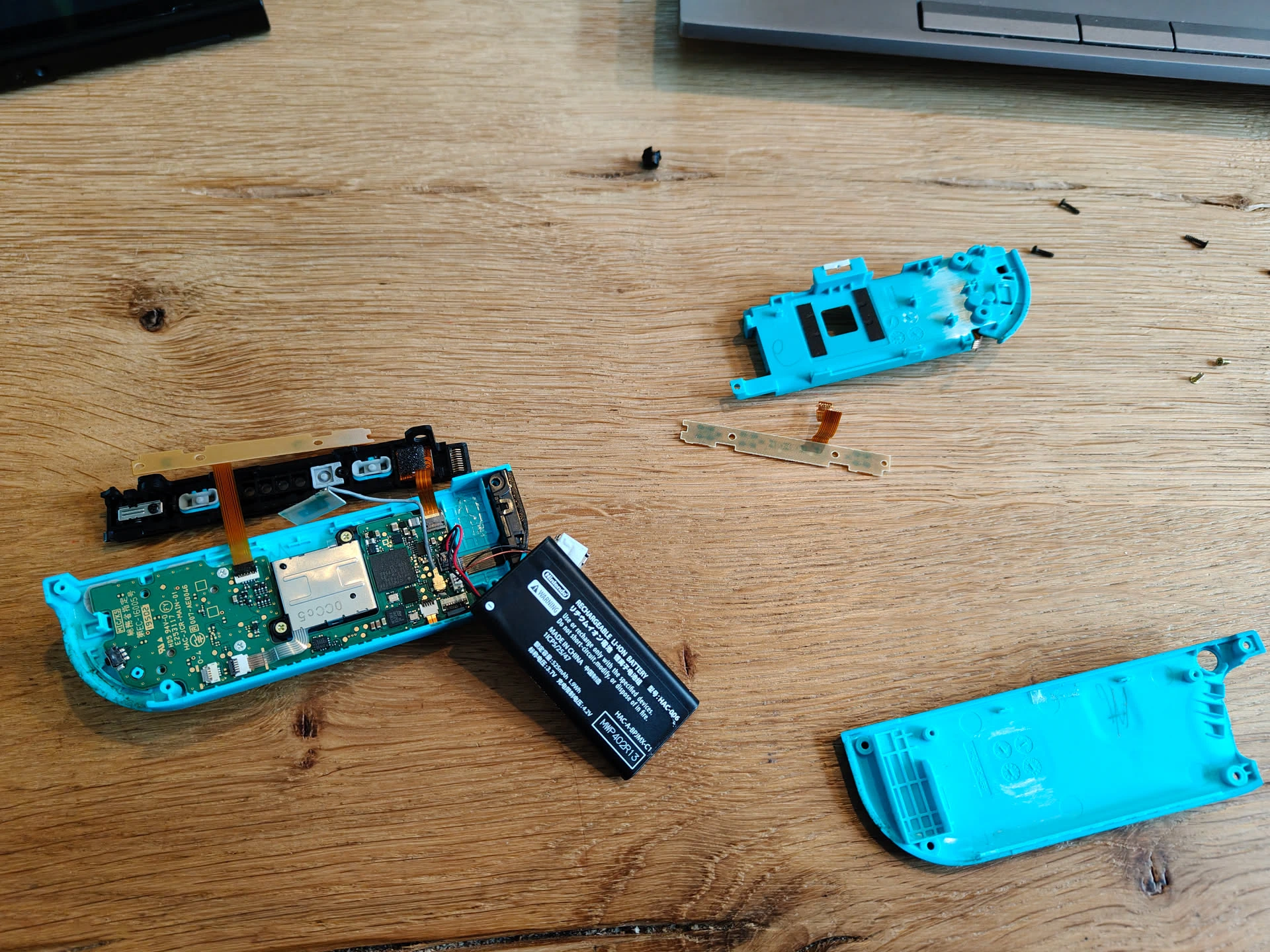
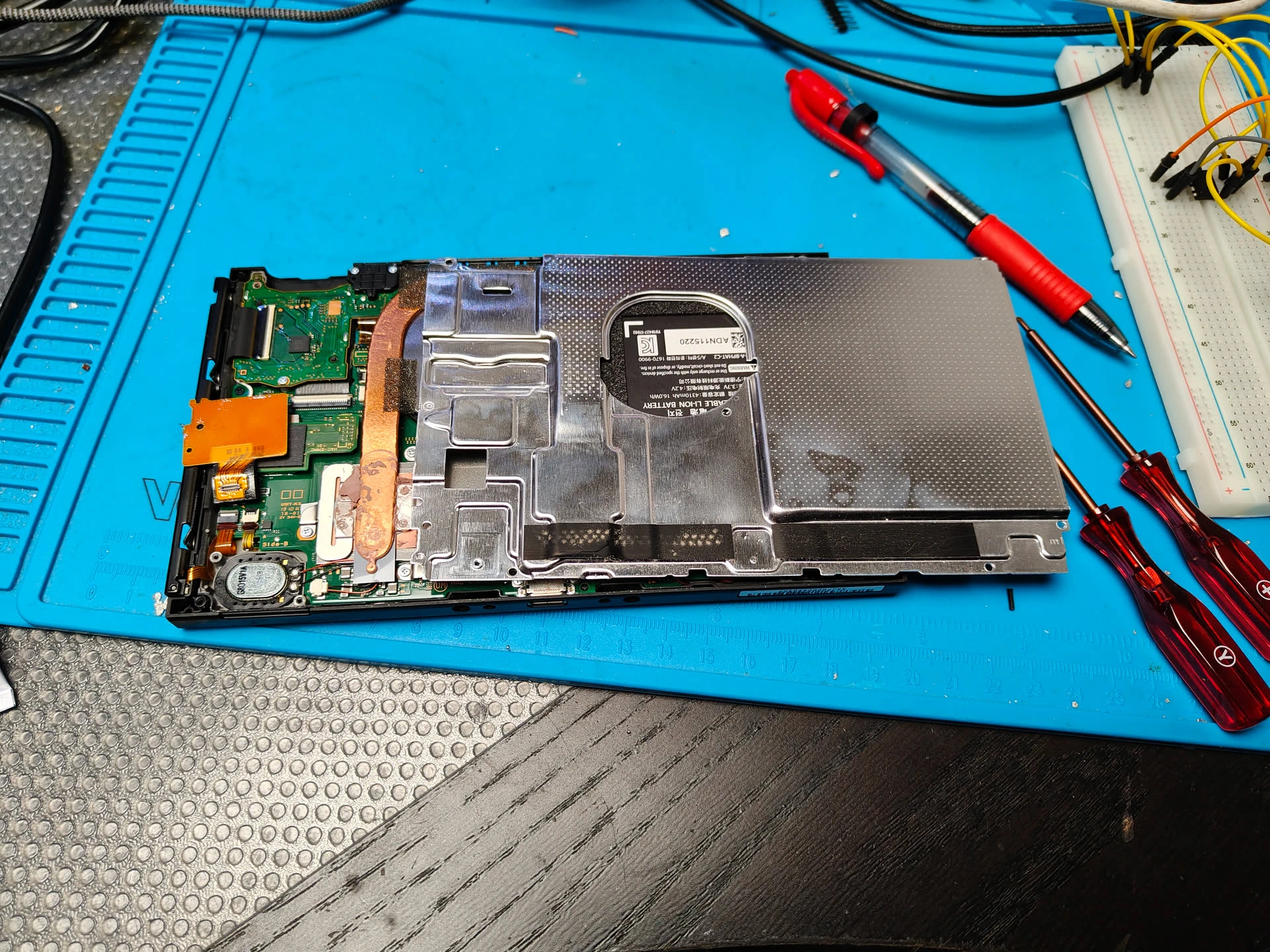
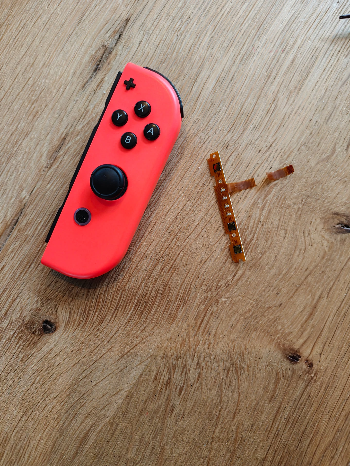
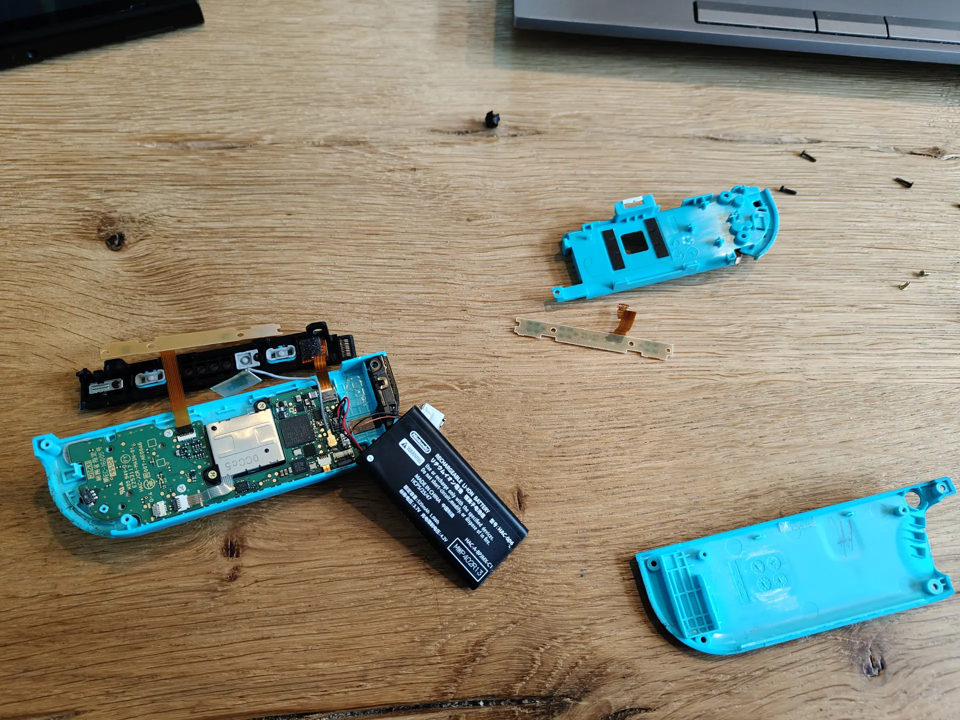
Last month i’ve been repairing Nintendo Switches.
Very small, and you need specialized tools.
Okay to do a few, but too small for my big hands.
I fixed multiple controllers, cardreaders and a gamecard.
Last month i’ve been repairing Nintendo Switches.
Very small, and you need specialized tools.
Okay to do a few, but too small for my big hands.
I fixed multiple controllers, cardreaders and a gamecard.
One moment playing with LoRa. Next, a Nintendo Switch controller to fixed.
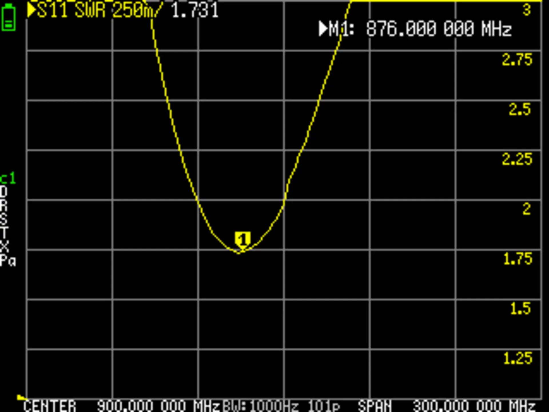
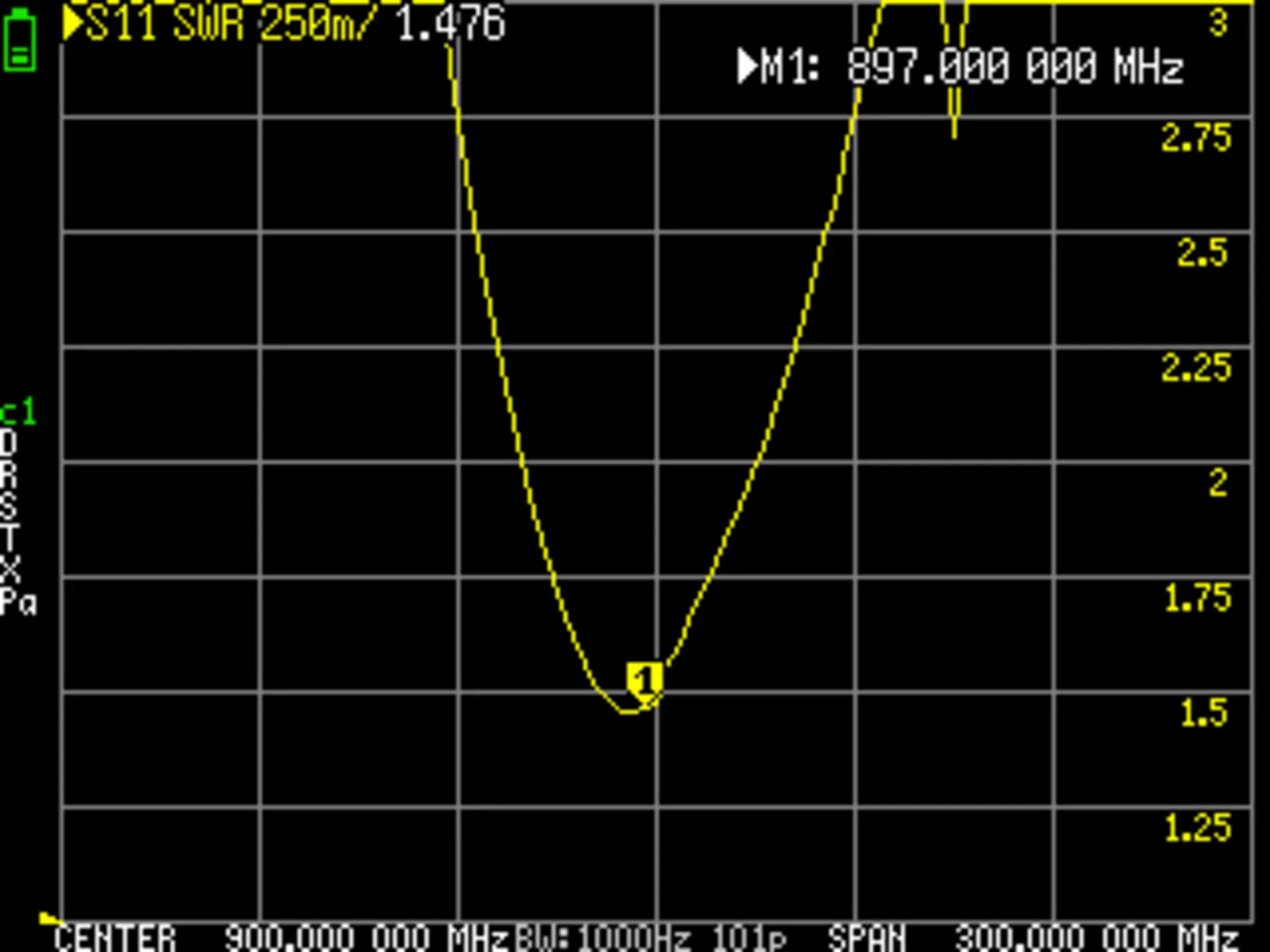
LoRa Antenna measurements
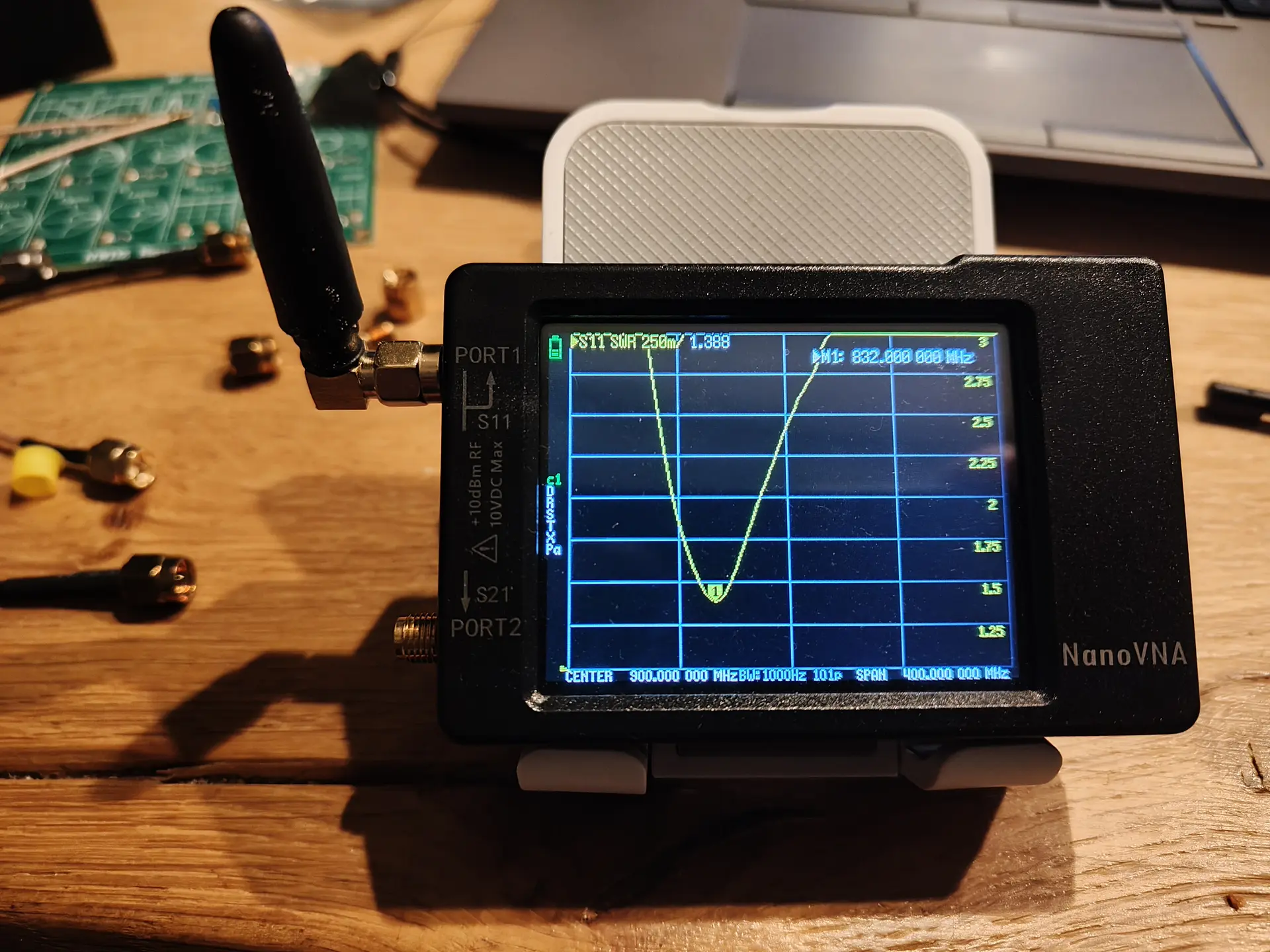
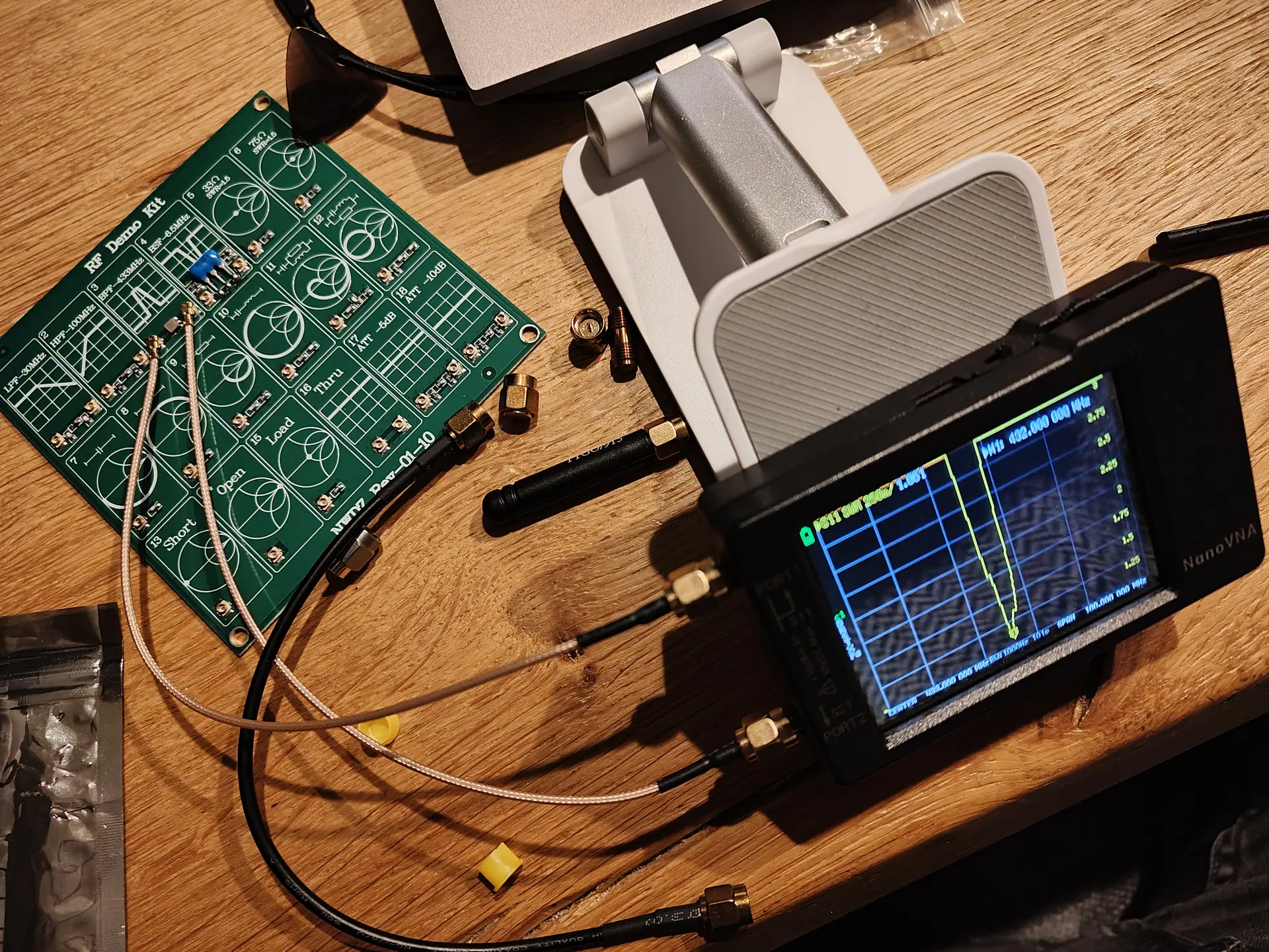
Using my NanoVNA and a RF test Kit I learned something about measuring antenna.
Below a measurement of a unknown antenna, ITs off, I need to shorten the metal spring inside.
Using CD74HC4067
Only partly drawn ..
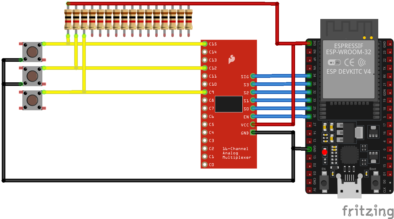
This will be for a multi level Whack-a-Mole.
Another game in the making is a Red Light – Green Light game.
Like in Squid Game.
This will use a lidar and a python script which detect movement using a camera.
While this is a old project from 2019, I decided to make a more responsive one, after my friend Tyrone mentioned a project somewhere on the internet (forgot where).
Time to dust off this project!
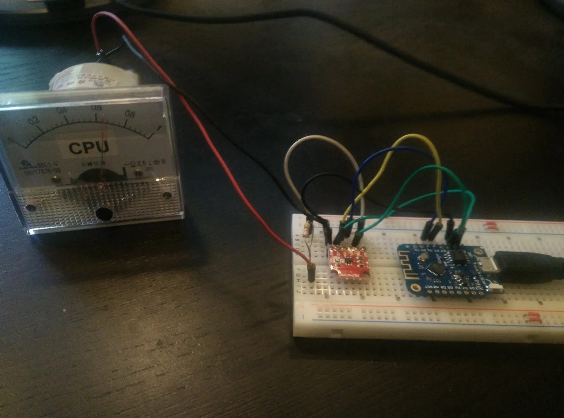
Above version worked but was slow.
I used a python script to send values to de controller.
Memory setup was the same.
Below my new schematic, using an opamp to drive the analog meter.
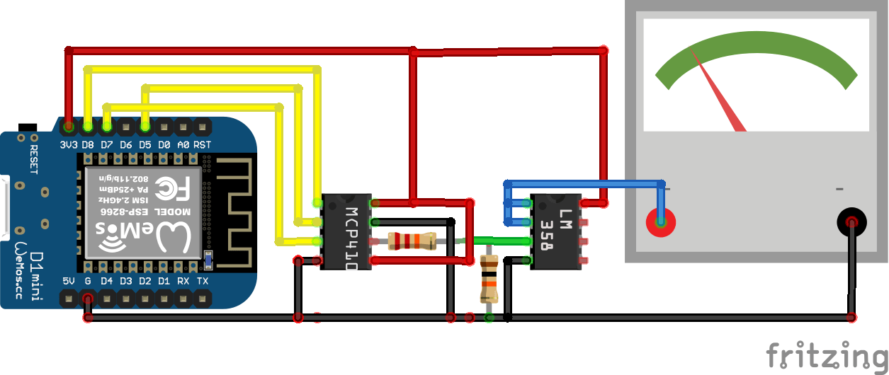
Utilizing a MCP41000 digital potmeter and a LM358 signal amplifier I hope to get a more responsive setup.
Input to display MQTT and maybe Serial.
These will be available in my shop.
Probably a webpage with measured examples are usefull.
Handheld device to measure voltages and make screenshots using an application.
Control over serial
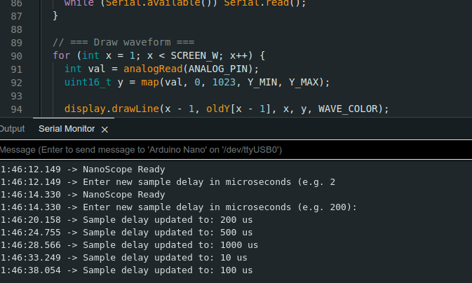
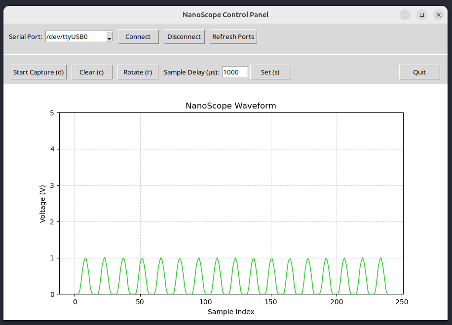
I’m currently working on streaming output.
Below, an example of screenshotting.
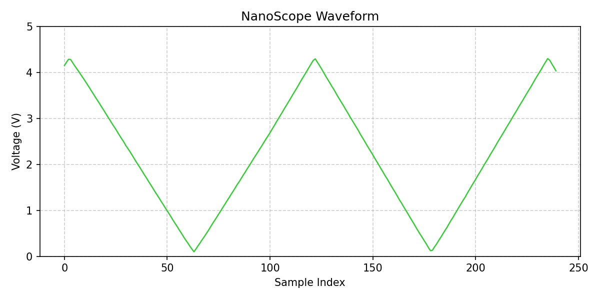
Below, measuring outputs from a NE555 (dutch comments)
Working on my garden lights
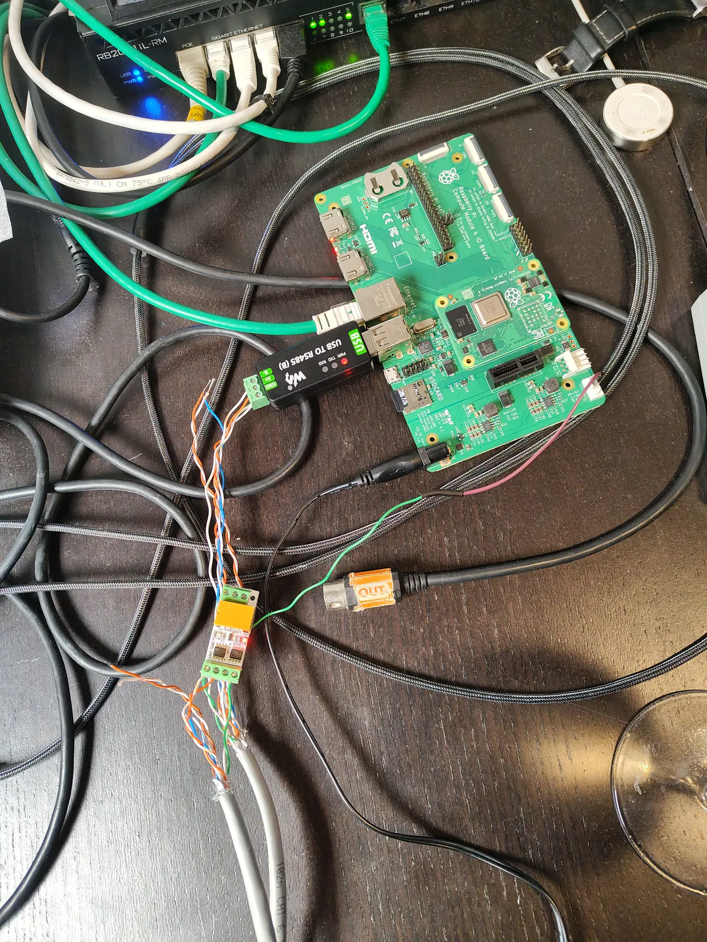
Working 12V relay bottom left, and upper right the Raspberry $ compute module board with NodeRed.
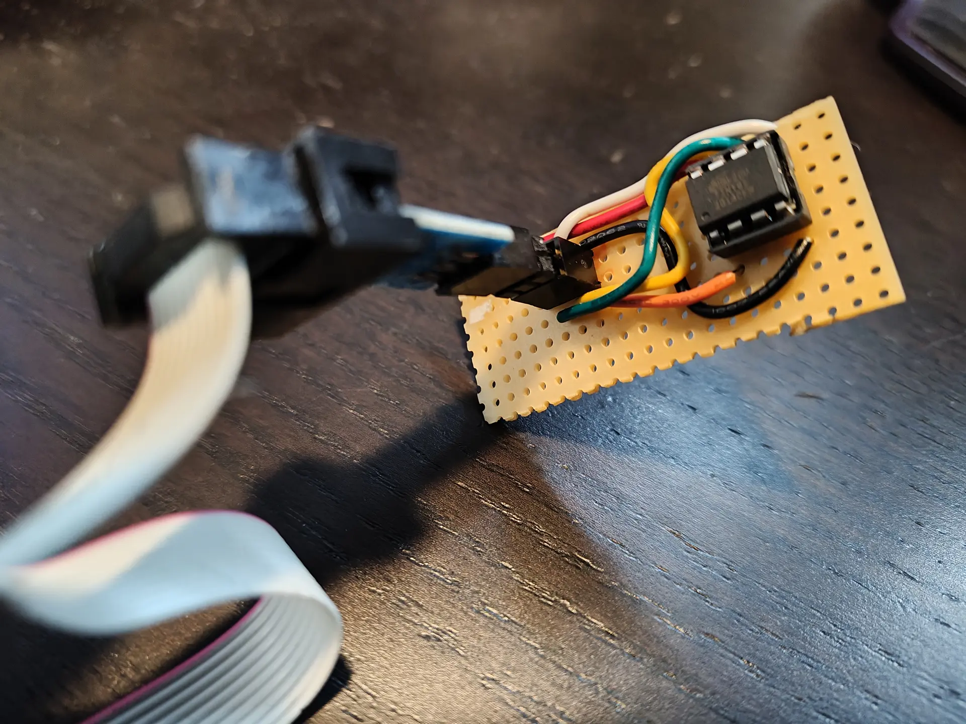
I made a little board to program the ATTiny85.
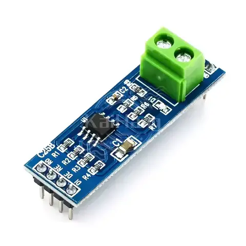
The RS485 chip I wanted to use (SN65HVD3082) came as SMD, luckily I have some SMD to THT/DIL boards. (breakoff)
Above on the breadboard : The SN65HVD3082EP on a little pcb, the ATTiny85 .
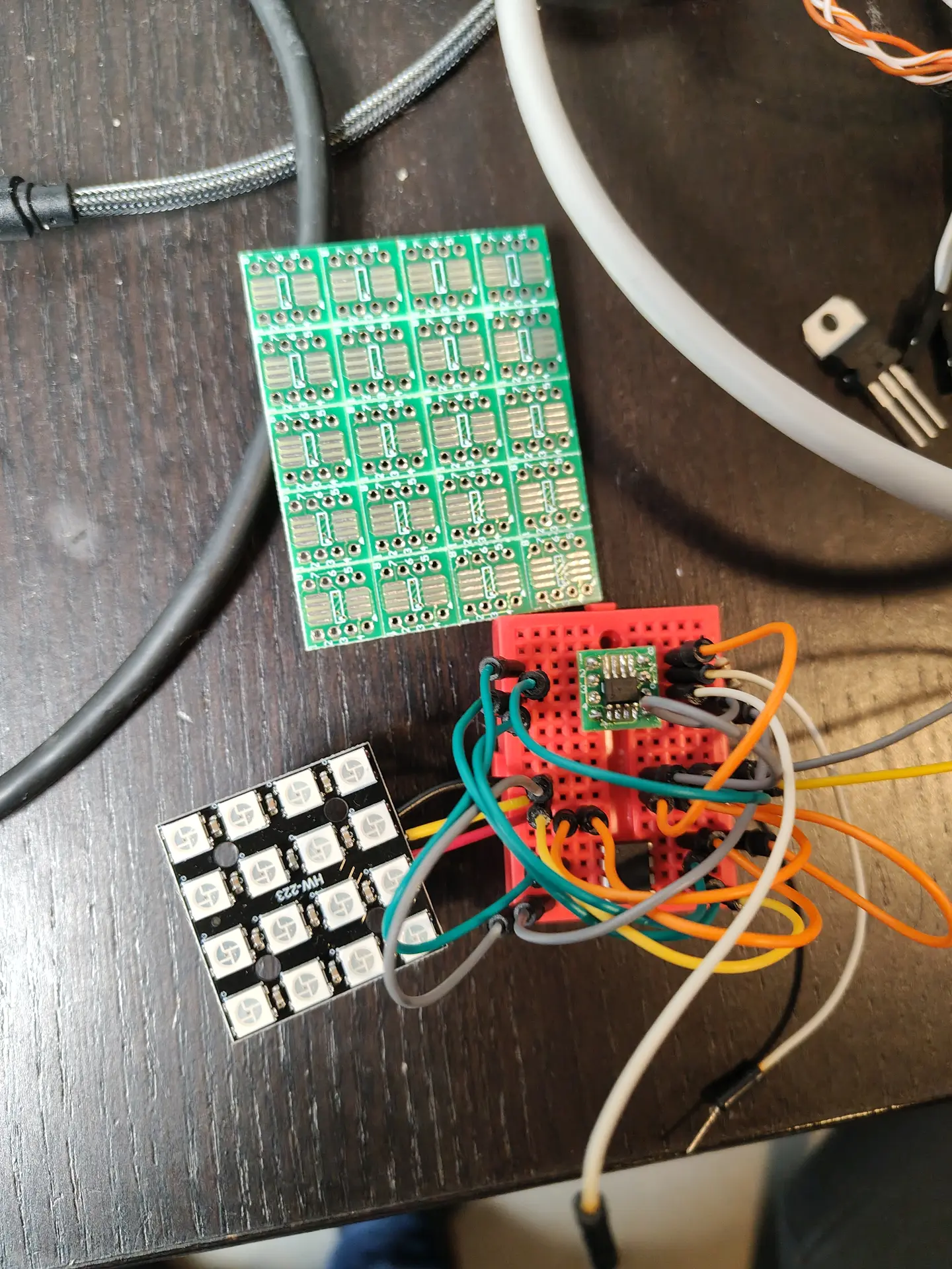
4×4 WS2812 led matrix will be my dimmable RGB garden light.
New version of :
New schematic using ESPHOME and has reset button (pressing the lid).
(Resets the LED when you’ve put the trash at the street curb.)

Above, a simplified version. I’m using 4 ws2812 leds now.
ESPHOME code:
esphome:
  name: afvalwemos
  friendly_name: AfvalWemos
  on_boot:
    priority: 800
    then:
    - delay: 1s
    - light.turn_off: main_leds

esp8266:
  board: d1_mini

# Enable logging
logger:

# Enable Home Assistant API
api:
  encryption:
    key: "bT76oR8vOxxxxxxxxxxxxxxxxxxxxxxxxQbyjY6M="

ota:
  - platform: esphome
    password: "c1dbxxxxxxxxxxxxxxxxxxxxxxxxxx36e75"

wifi:
  ssid: !secret wifi_ssid
  password: !secret wifi_password

  # Enable fallback hotspot (captive portal) in case wifi connection fails
  ap:
    ssid: "Afvalwemos Fallback Hotspot"
    password: "vVxxxxxxxxxxxxxxaw"

captive_portal:

# LED strip definition
light:
  - platform: neopixelbus
    type: RGB
    variant: WS2812
    pin: D5
    num_leds: 4
    name: "All LEDs"
    id: main_leds
    restore_mode: ALWAYS_OFF   # ensures all LEDs start off


  # Individual LED partitions
  - platform: partition
    name: "LED 1"
    segments:
      - id: main_leds
        from: 0
        to: 0

  - platform: partition
    name: "LED 2"
    segments:
      - id: main_leds
        from: 1
        to: 1

  - platform: partition
    name: "LED 3"
    segments:
      - id: main_leds
        from: 2
        to: 2

  - platform: partition
    name: "LED 4"
    segments:
      - id: main_leds
        from: 3
        to: 3


# Physical button on D6 to turn off all LEDs
binary_sensor:
  - platform: gpio
    pin:
      number: D6
      mode: INPUT_PULLUP
      inverted: True
    name: "All Off Button"
    on_press:
      - logger.log: "Button pressed — turning all LEDs OFF"
      - light.turn_off: main_leds
Home Assistant automation:
alias: Afvalwijzer Plastic
description: Afvalwijzer leds
triggers:
  - at: "18:00:00"
    trigger: time
conditions:
  - condition: template
    value_template: >
      {% set raw = states('sensor.gad_pmd') %} {% if raw not in ['unknown',
      'unavailable', 'none', ''] %}
        {% set clean = raw.replace('Tomorrow, ', '').replace('Today, ', '').strip() %}
        {% set parts = clean.split(', ') %}
        {% set date_part = parts[-1] if parts|length > 1 else clean %}
        {% set pmd_date = strptime(date_part, '%d-%m-%Y').date() %}
        {% set tomorrow = (now().date() + timedelta(days=1)) %}
        {{ pmd_date == tomorrow }}
      {% else %}
        false
      {% endif %}
actions:
  - action: light.turn_on
    target:
      entity_id: light.afvalwemos_led_3
    data:
      rgb_color:
        - 236
        - 199
        - 14
mode: single
Remember those expensive touch lights you can buy?
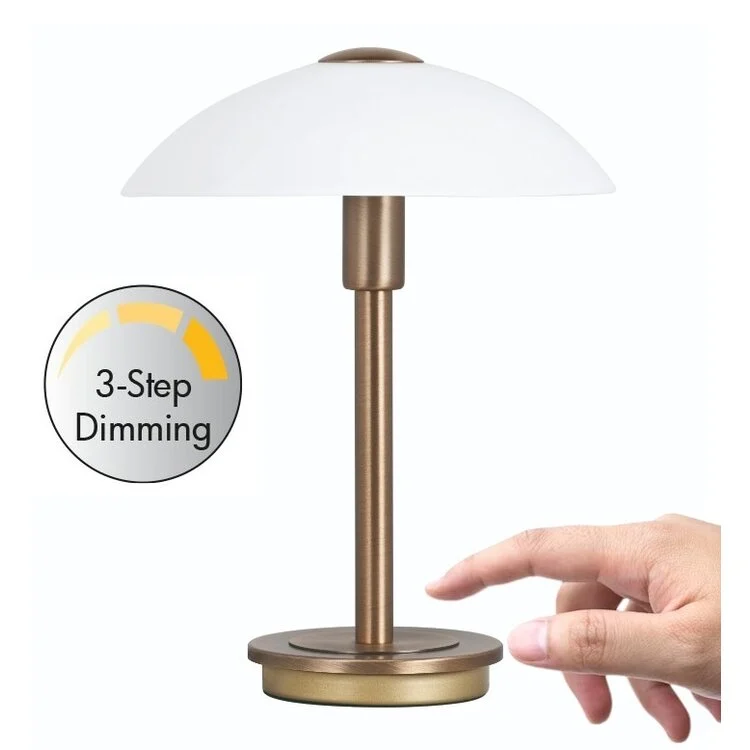
This is a less than 5 euro version.
Warning : Some tricks I used
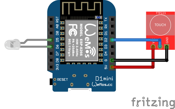
TTP223 sensors are only a few cents!
And react even without touching (< 5mm)
So, you can build this in a case or behind fabric!
NOTE: If you are using an ESP32 you can configure a pin as touch!!!
So no TTP223 needed.
But ESP32 are more expensive as Wemos mini.
Code:
#define TOUCH_PIN D2 // My video has D7
#define LED_PIN   D6
#define FAKE_GND D5

// Brightness steps (0 = off, 255 = full bright)
int brightnessLevels[] = {0, 25, 125, 255};
int currentLevel = 0;
bool lastTouchState = LOW;

void setup() {

  pinMode(TOUCH_PIN, INPUT);
  pinMode(LED_PIN, OUTPUT);
  pinMode(FAKE_GND, OUTPUT);

  digitalWrite(FAKE_GND, LOW);
  analogWrite(LED_PIN, brightnessLevels[currentLevel]);  // start OFF
}

void loop() {
  bool touchState = digitalRead(TOUCH_PIN);

    if (touchState == HIGH && lastTouchState == LOW) {
      // Advance brightness step
      currentLevel = (currentLevel + 1) % 4;  // 0-3 steps
      int pwmValue = brightnessLevels[currentLevel];
      analogWrite(LED_PIN, pwmValue);
    }

  lastTouchState = touchState;
}
Dim levels less obvious on recording, but you can change the levels in the code!
We are planning to redo our garden. And I am making a water and light plan for it.
I thought I could do it myself using 12V and RS485/Modbus.
So these are my plans. (NOTE, this is a work in progress)
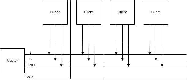
I’m going to put 4-wire ground cable in our garden, and a RS485/Modbus master controller in my shed.
4 Wires will have 12V low voltage, ground and RS485 A/B wires.
This way I can control till 64 devices on a single cable.
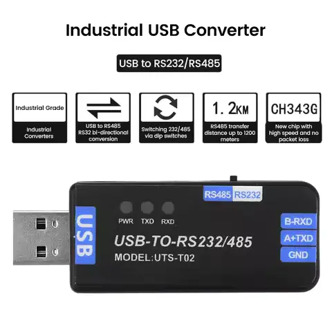
Below, a USB stick to connect the RS485 cables to a Raspberry Pi?
Software is probably going to be a NodeRed instance connected to Home Assistant.
On/Off lights using a RS485 board and relay. These can be bought on a single PCB and can control 220V. I am probably going to use generic outside lamps and refit them for 12V led or 220v, with those RS485 controllers.
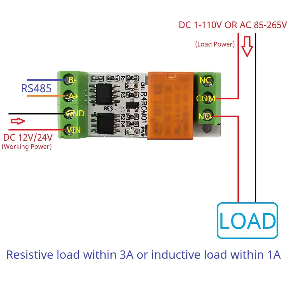
The above left part will be encased in resin or alike.
Right PCB is for testing only.
For dimming RGB lights, I made the below design.
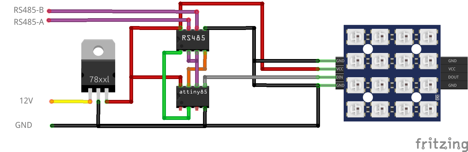
12V to 5V using a 7805, RS485 8pin DIL/DIP and a ATTiny85 8pin DIL/DIP. Plus a 4×4 RGB Matrix.
These also encased in resin.
More information on the ATTiny85 and programmer can be found here:
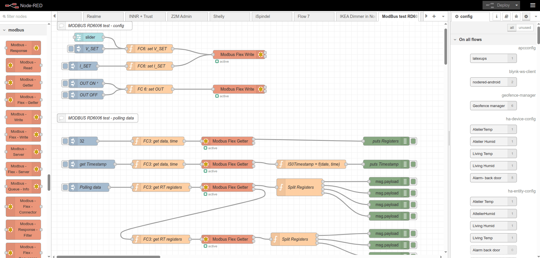
Modbus using NodeRed (I’ve used this to control my RD6006 Lab Power Supply)
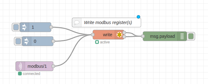
Bare minimal to control the relay.
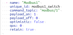
HA control via MQTT
While I made this for my Commodore C64, it is applicable for many things.
It started with some cheap displays from Ali, and some leftover Wemos D1 from my Pressure Lab project.
I Started measuring the audio output from sound devices and from my C64.
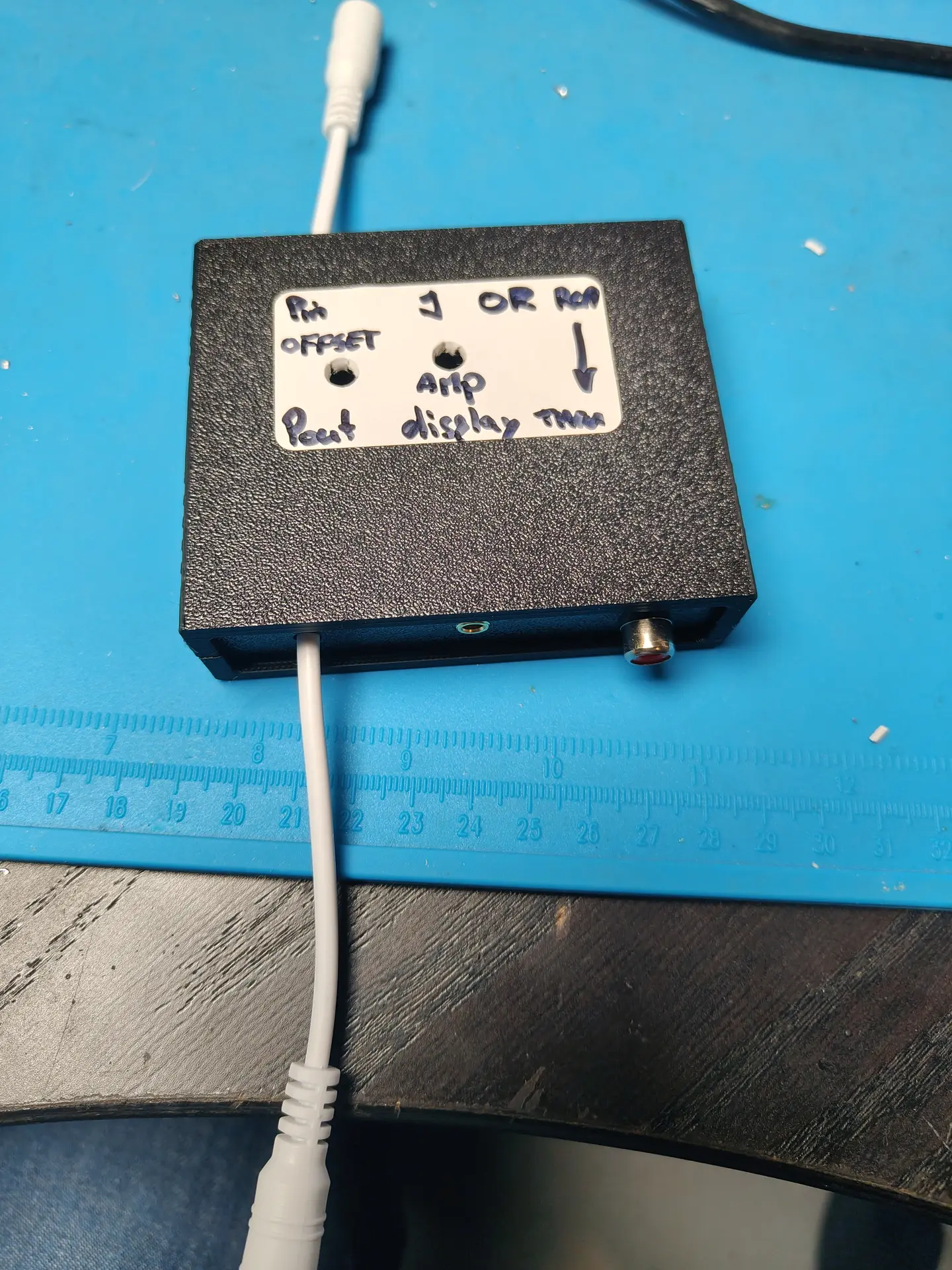
I soon discovered that I needed some way to get the offset and amplification correct for the analogue input of a Wemos. (0-3v3)
So a little op-amp circuit was born, but not without some struggles.
I forgot many things about amplifiers. It was one of the first school books I got rid of. (Sorry mister Rafaela)
After searching the internet and posting a question on Reddit I ended up with the following.

R1 and R2 are 100M. The potentiometer P1 allows me to set the offset.
R3 is 1M
C1 is 100nF to decouple the audio signal from the RCA.
R4 is 47K and C2 is 330nF (thanks tycho205)
Cimportant=1/(2πfR2)
where f is the lowest frequency of interest. In this case Cimportant should be about 330nF
LM324 is a quad amplifier, leftover from another project.
Note, the SINGLE RAIL power.
P2 potentiometer is 2M (leftover) and gives me a variable amplifying opportunity.

A = Audio input
B = Setting the offset with P1
C = Setting the amplification

The displays are 3 Wemos controllers with a cheap I2C display.
These are just fast enough to do FFT.

Analogue in is the output from the OP-amp offsetter ..
CODE
Needs cleaning up, and a better stabilizing routine.