Last Updated or created 2024-06-07
While busy fixing my business site, and working for a customer, I build a testing rig for the 68000.
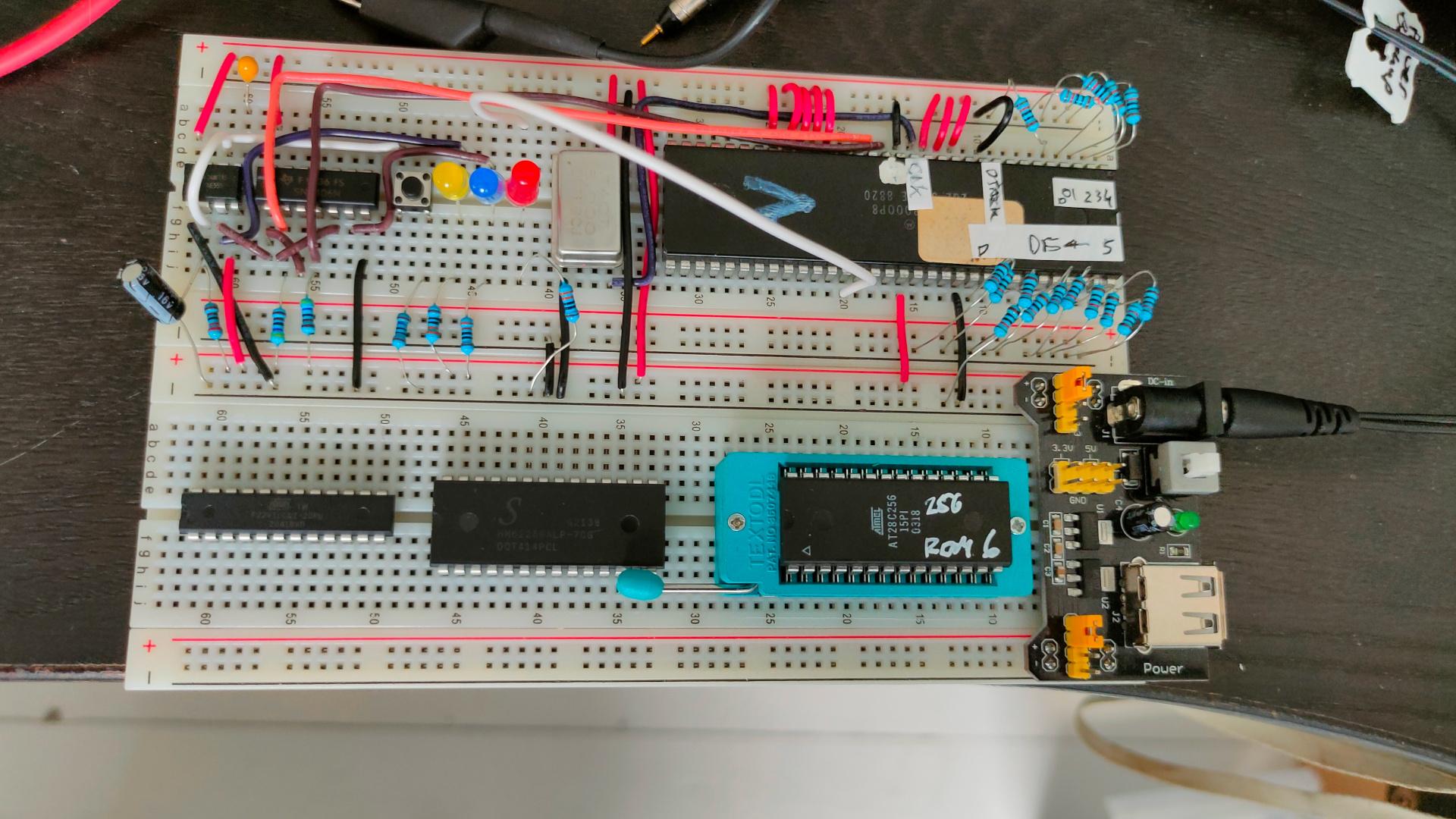
I first made a power-on reset schematic.
The timing is different from the 6502 power-on reset, and the 68k needs HALT and RESET being pulled low.
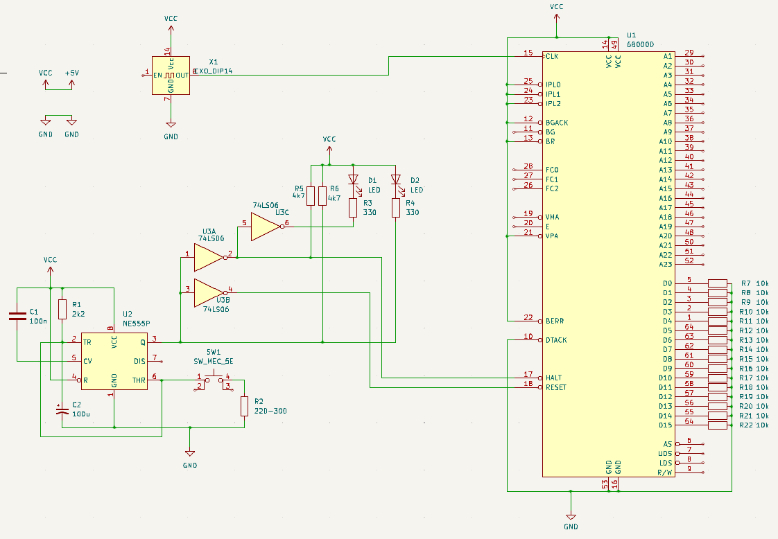
Lines pulled to GND or VCC are at least needed to get a running CPU.
Data bus resistors are needed because data is r/w
All Data lines are pulled low, emulating opcode 00 00
https://68k.hax.com/ORI%20to%20CCR
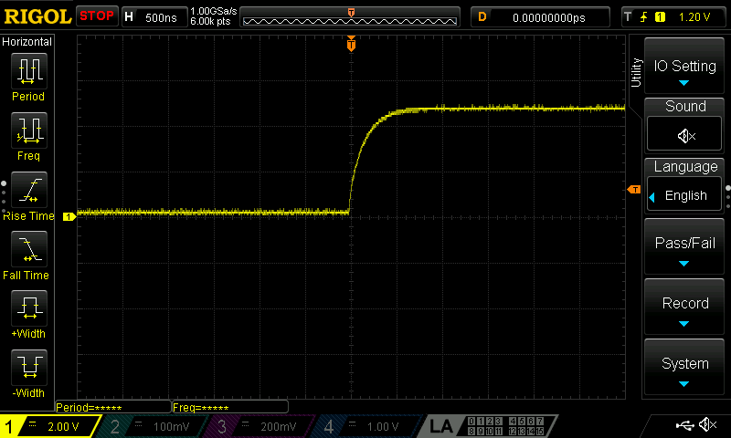
This will do nothing weird, and will increment the address and try to read the next opcode.
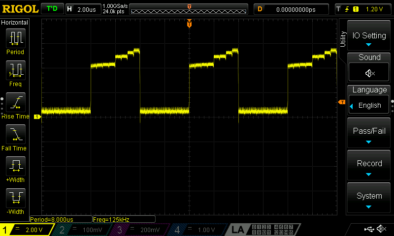
Resulting in an endless incrementing address bus, I’ve put a Led (Red)on Address A17.
Yellow is /RESET signal and Blue /HALT