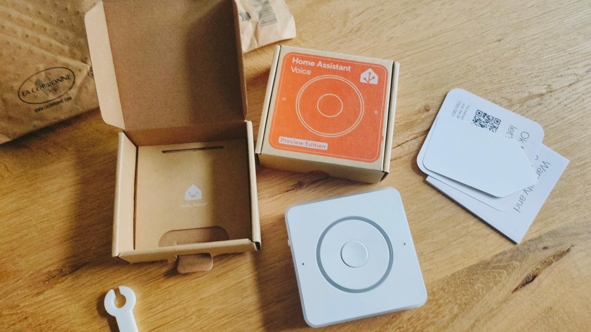
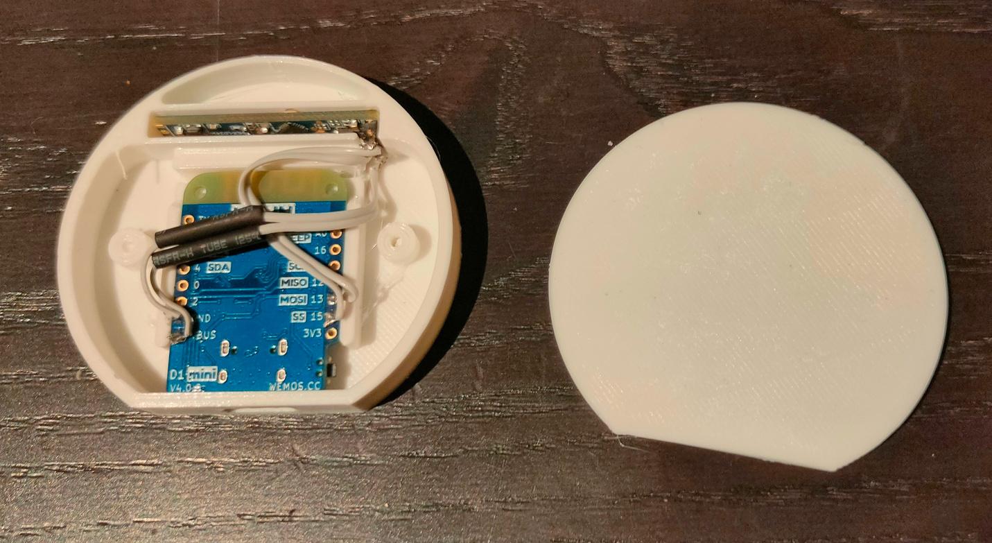
This is a Non-Cloud solution like Alexa and Google devices. I only could play with it for a few minutes because I was working on Arduino code with an ILI9341 Display and a BME280 (Temperature/Humidity/Air pressure).
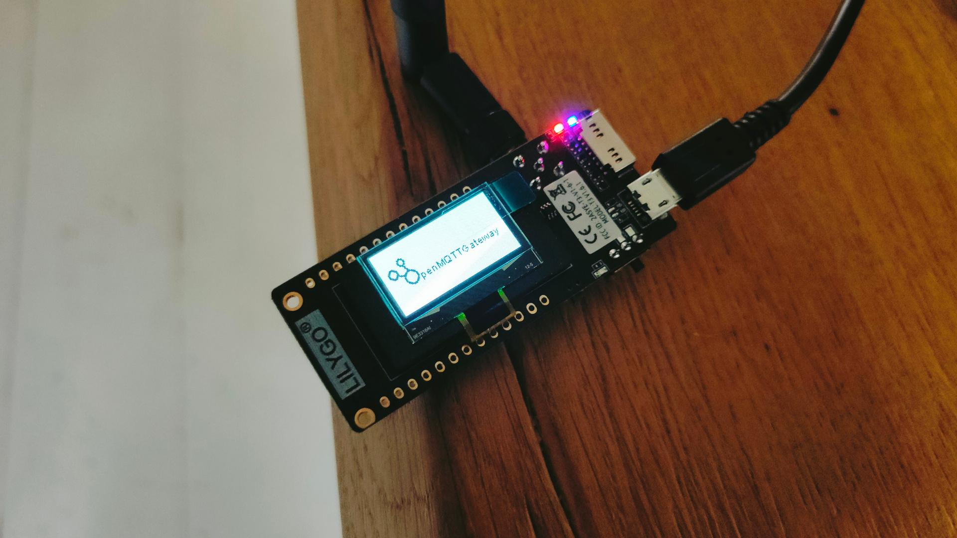
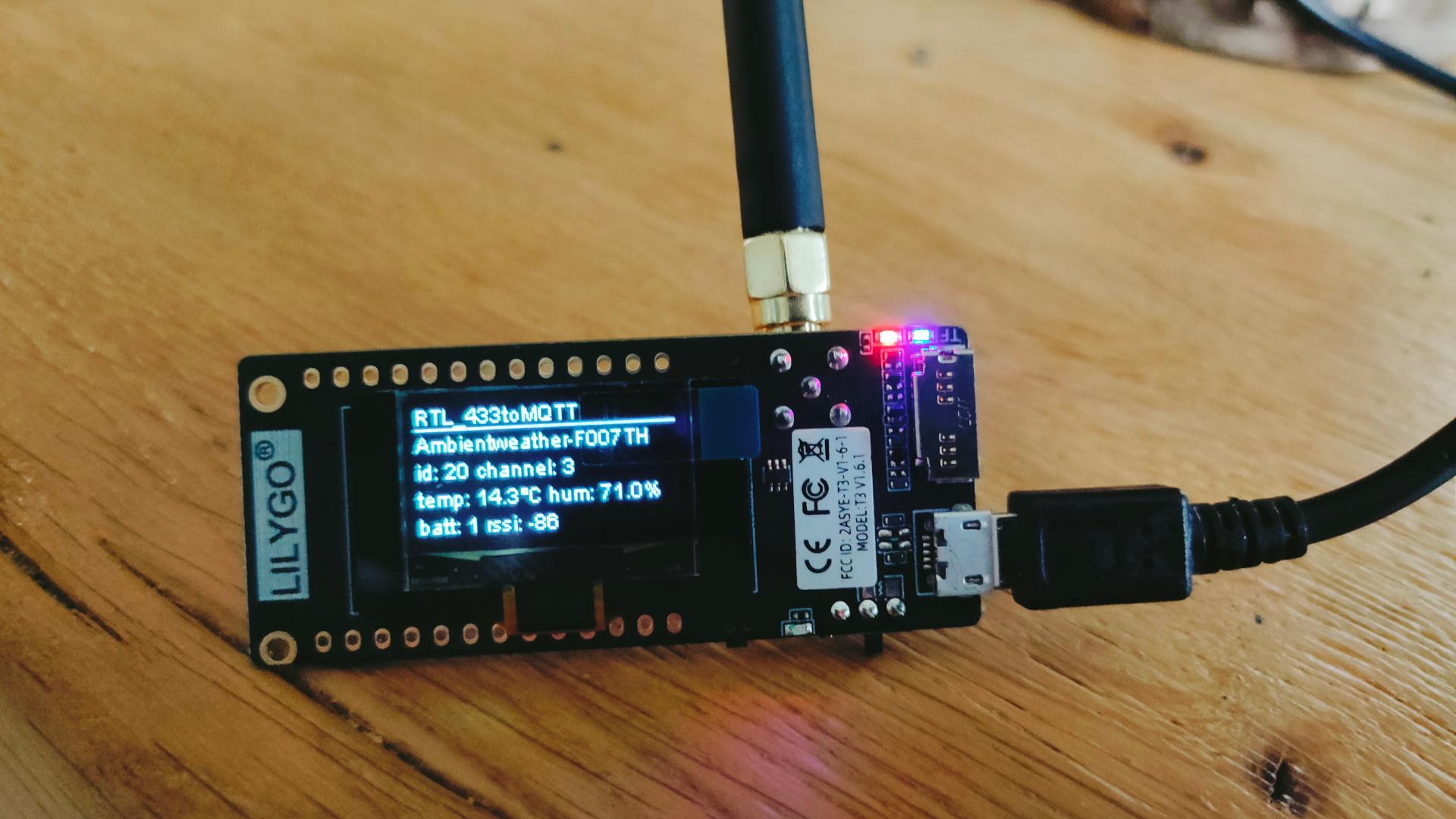
Today I got some new goodies in, one of these is a LilyGO LoRa display which works on 433 Mhz.
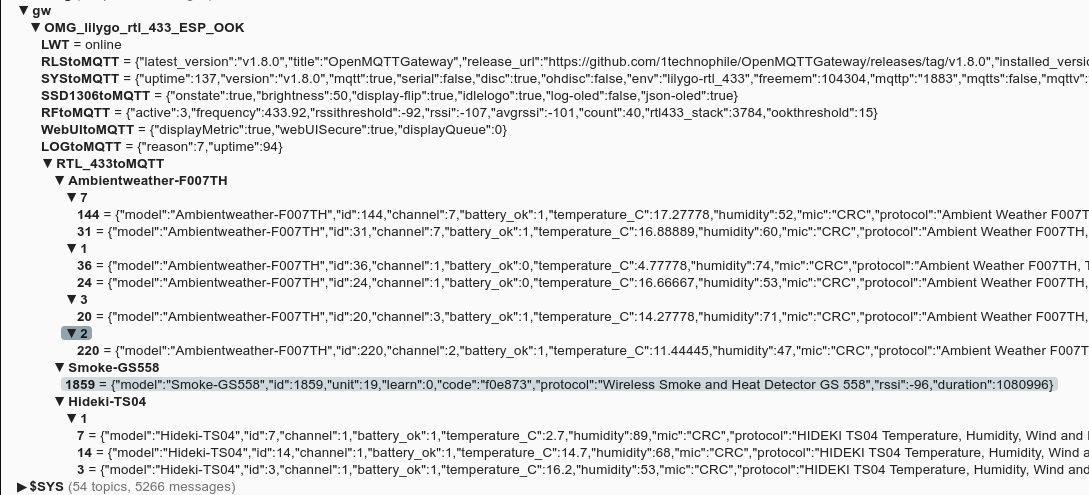
I flashed OpenMQTTGateway on this device.
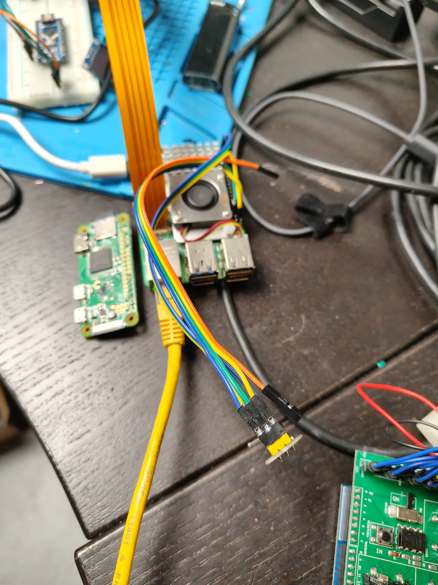
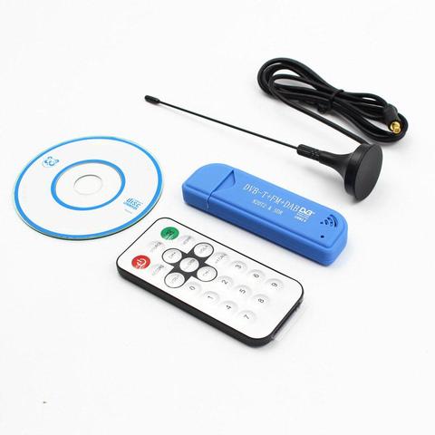
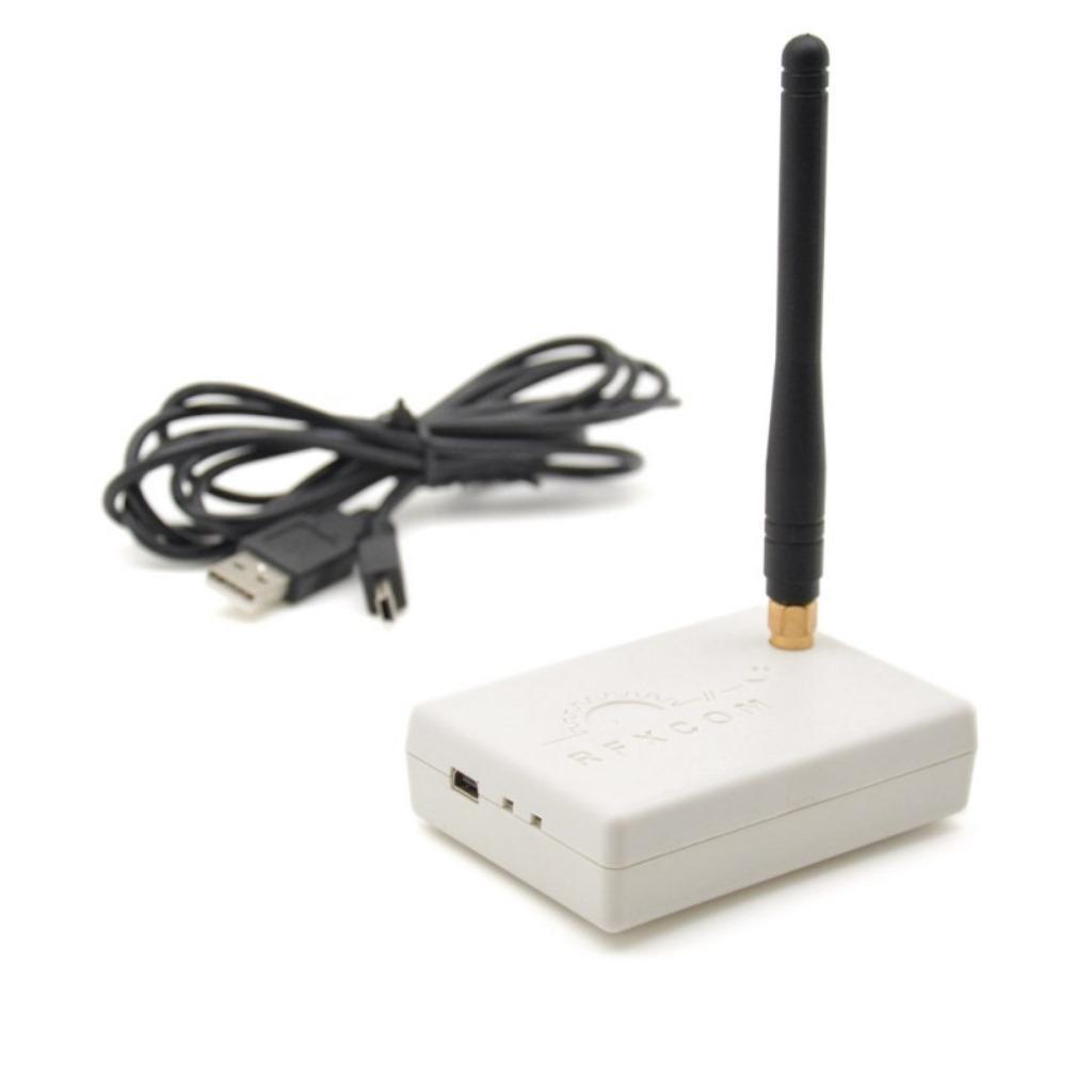
In the past, I posted about the RFCOM Gateway using Domoticz. This runs on a Raspberry Pi. While looking for alternatives, I found a rtl-sdr solution.
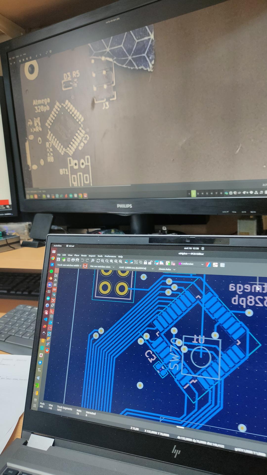
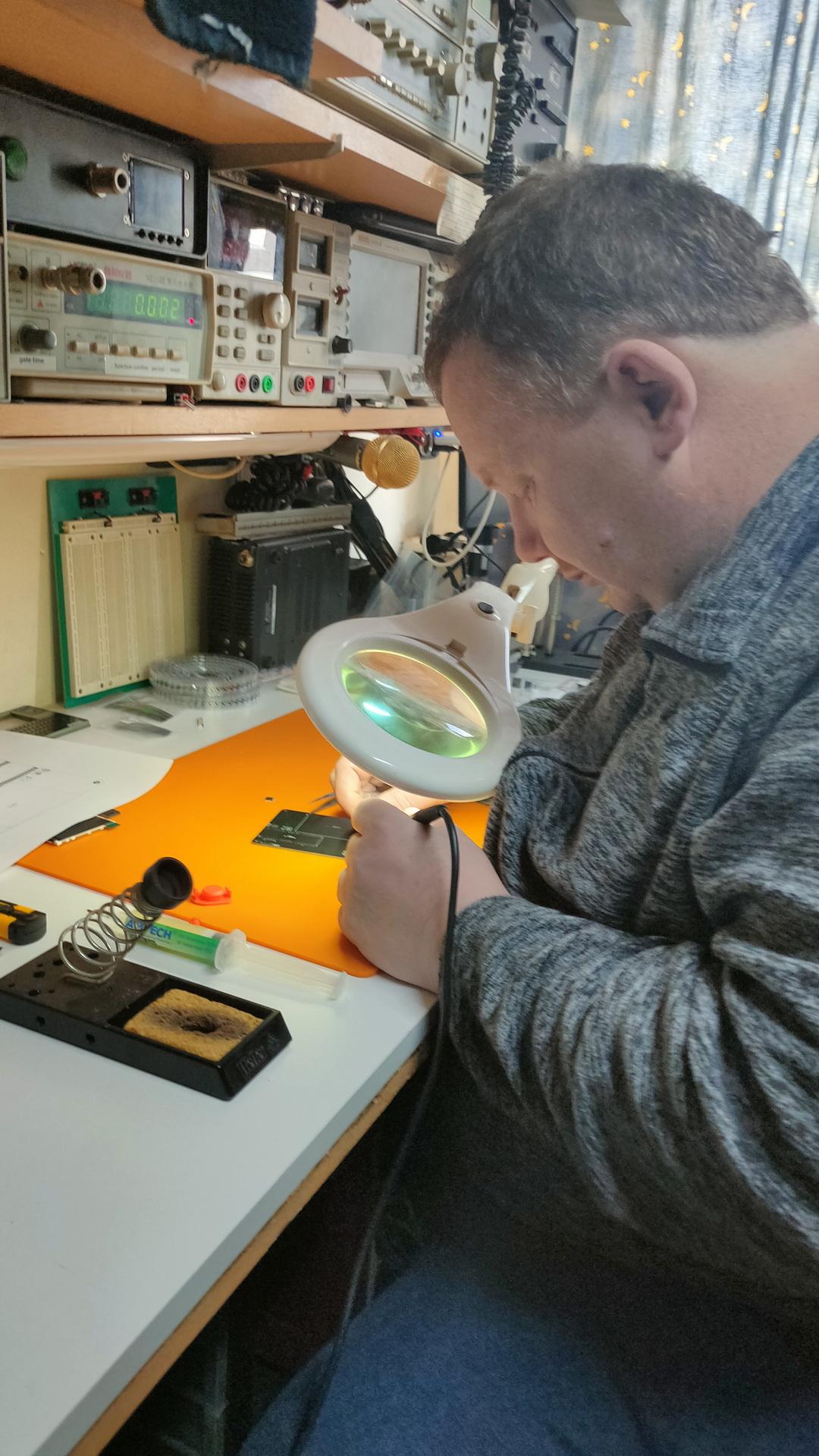
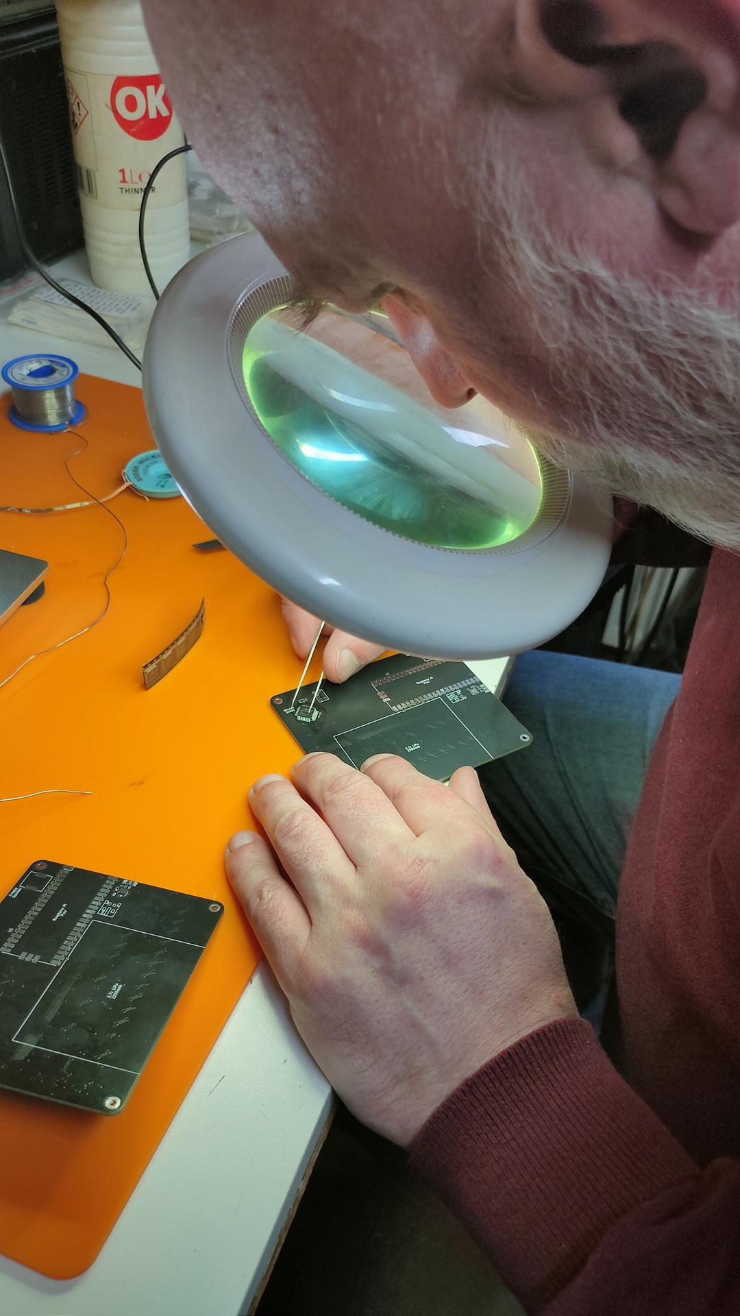
I was afraid to start this myself, SMD is on another level for me. But my good friend Marco said … No problem!
So I ordered components online, which was not easy. Selecting the correct parts, sizes and options.
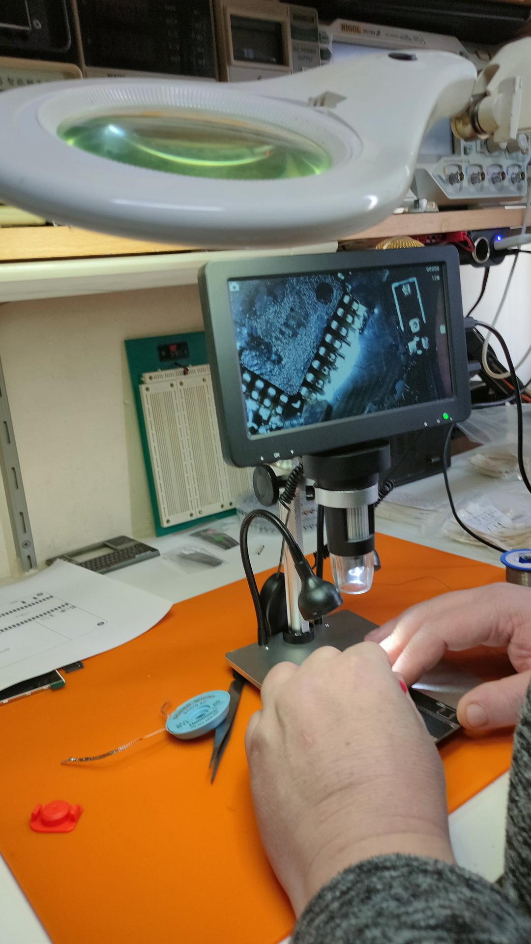
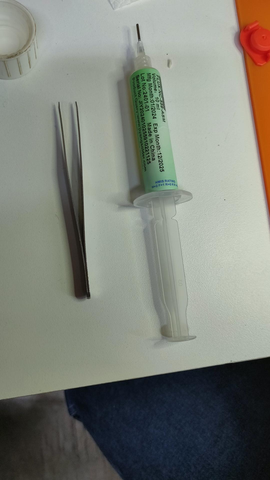
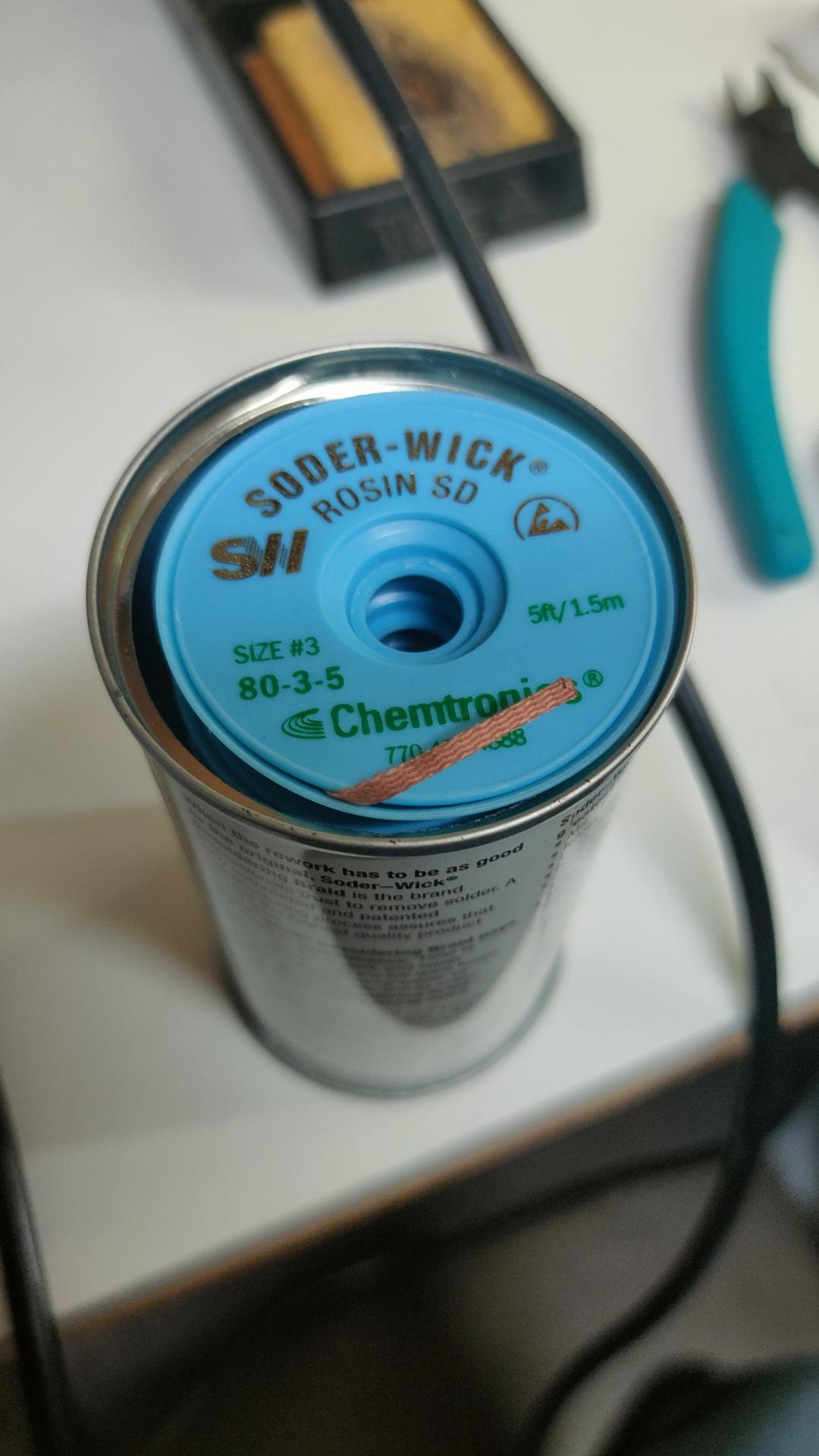
Finding orientations of the componentsThe master at work, he has always been our soldering master (see GPC)Using a microscopeFluxWickI have to do one myself
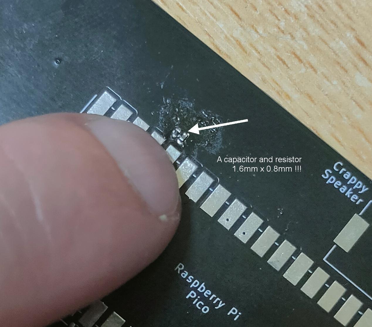
These things are really really small
1.6mm x 0.8mm40 connections / 20mm !
Using tweezers to place the components was even difficult. The slippery tiny bastard got catapulted everywhere. (Or got stuck on fingers, soldering iron and alike) Many small components got lost into the 7th dimension. Never to be found again.
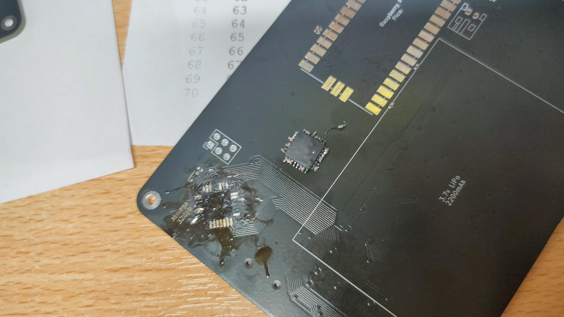
Awesome to work on this together, but Marco said that I have to try it myself. Welllll, I got 3/4 of the ATmega328PB-A perfectly soldered, then I notished that it was crooked. Desoldering was a mess, and I heated the PCB TOO much with the heatgun.
My messed-up PCB, and f*cked-up IC. Leave it to the professionals.
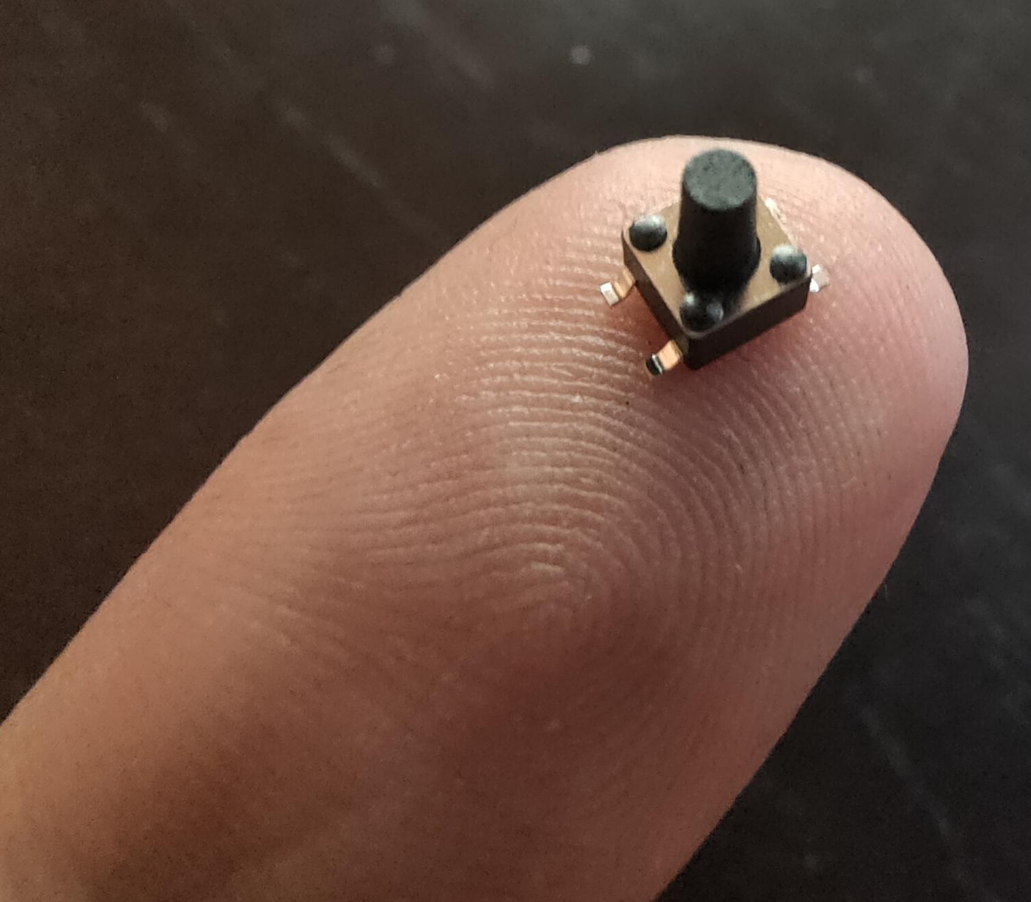
Next step for me is soldering the 75 mini buttons!
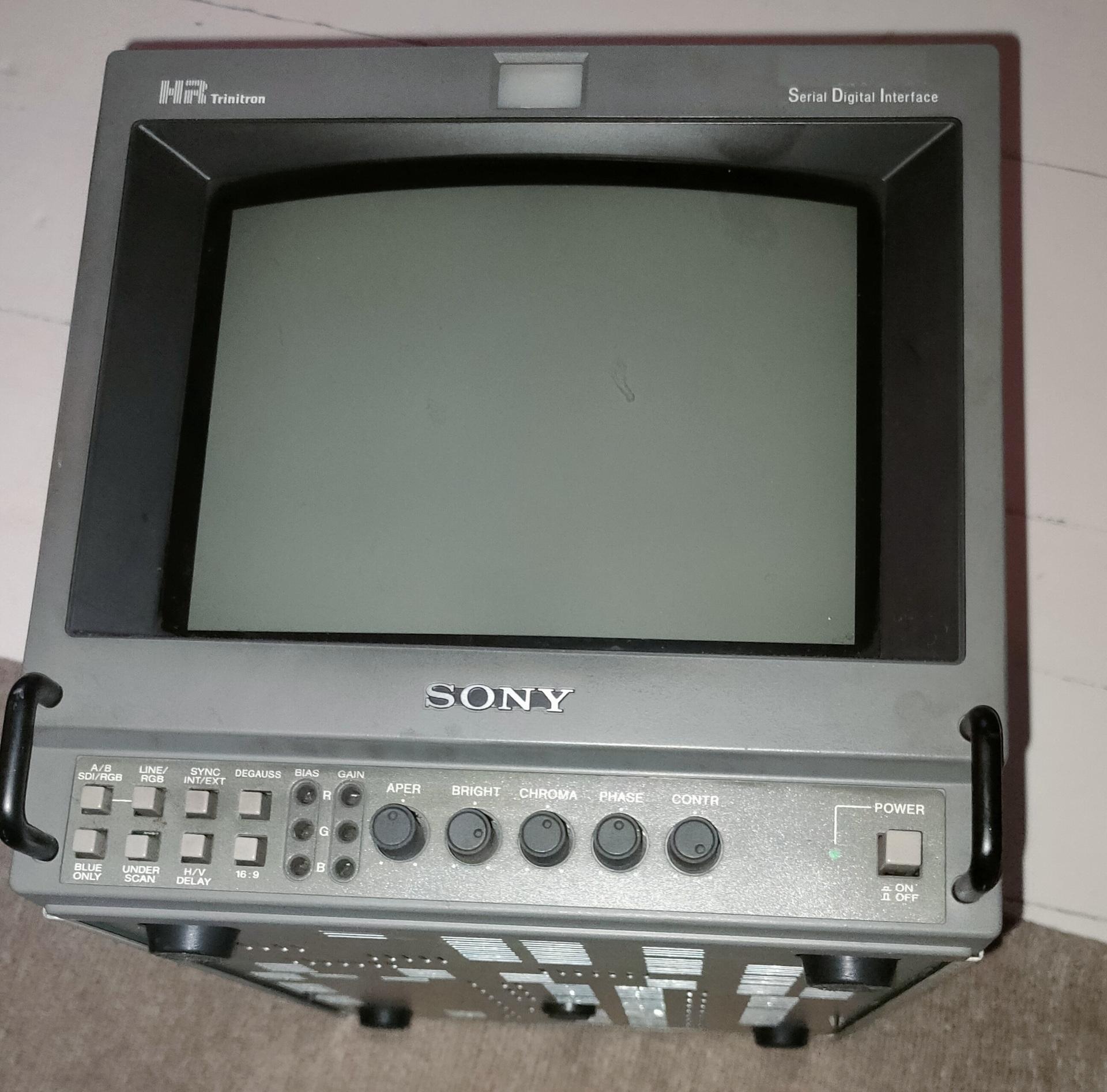
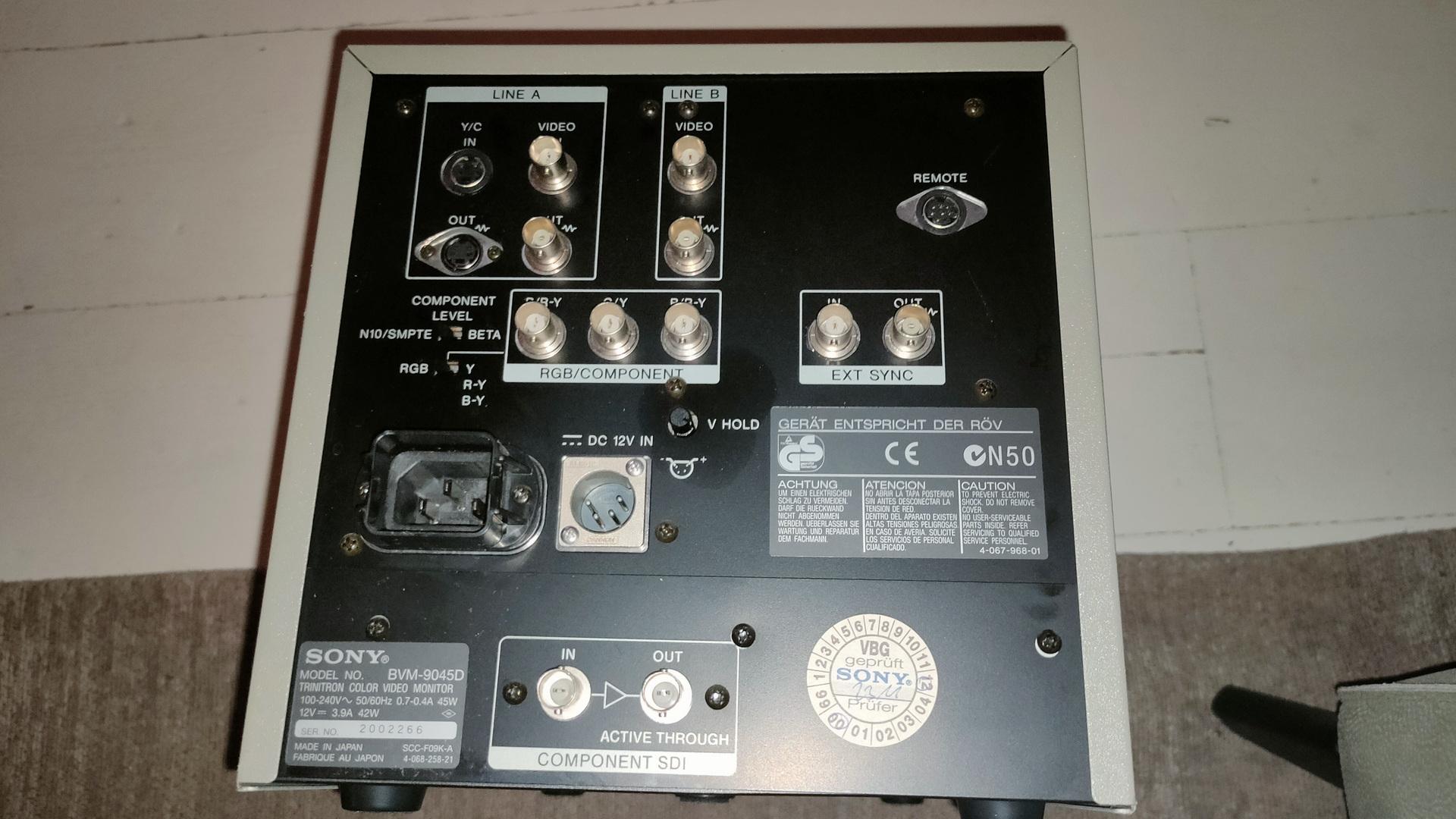
Got a Trinitron display from him, I was looking for this for a long time.
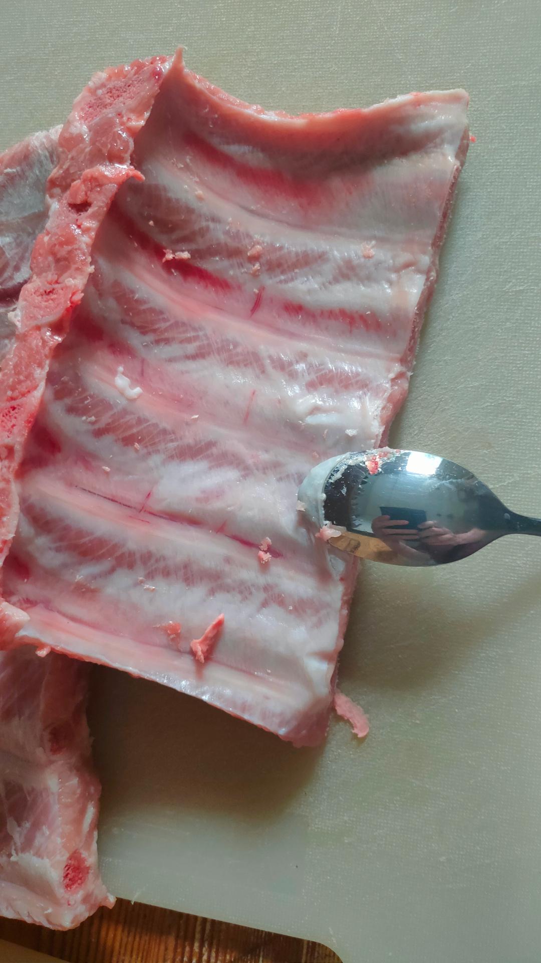
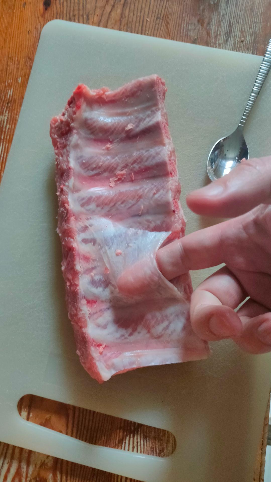
Use a little spoon NOT a knifeGet your fingers underneath the membranePreparing the ribs, getting the membrane off.
This time I used a rub with the following ingredients: Seasalt, garlic, brown sugar, mustard seeds, paprica, cilantroseeds, black pepper, red pepper, oregano, thyme and cumin.
Doing a simple 3-2-1 smoke session, so .. what to do in dose 6 hours?
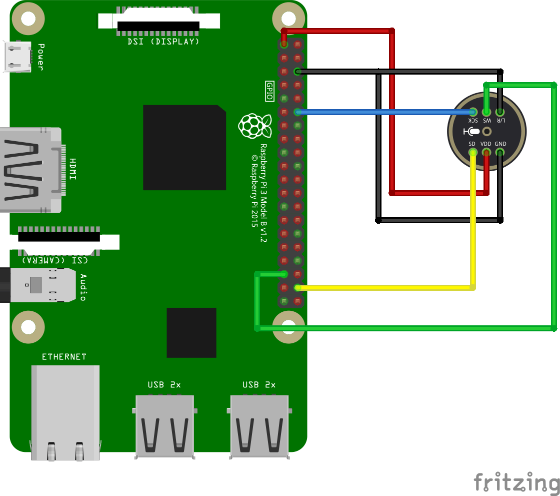
Lets make something using a Sense hat and Python. Same HAT I used for my xmas ornament thingy in our tree.
Generate a large maze (80×80 for now)
Paint the maze using colors on the SenseHat
Read joystick movement and scroll the maze accordingly, keeping the player in the middle
Now I have to paint my ribs with BBQ sauce, and leave it in the smoker for yet another hour. (Nice glazing)
Next steps for the maze:
Use a better way to generate (reverse backtracking as I made for my other maze thing)
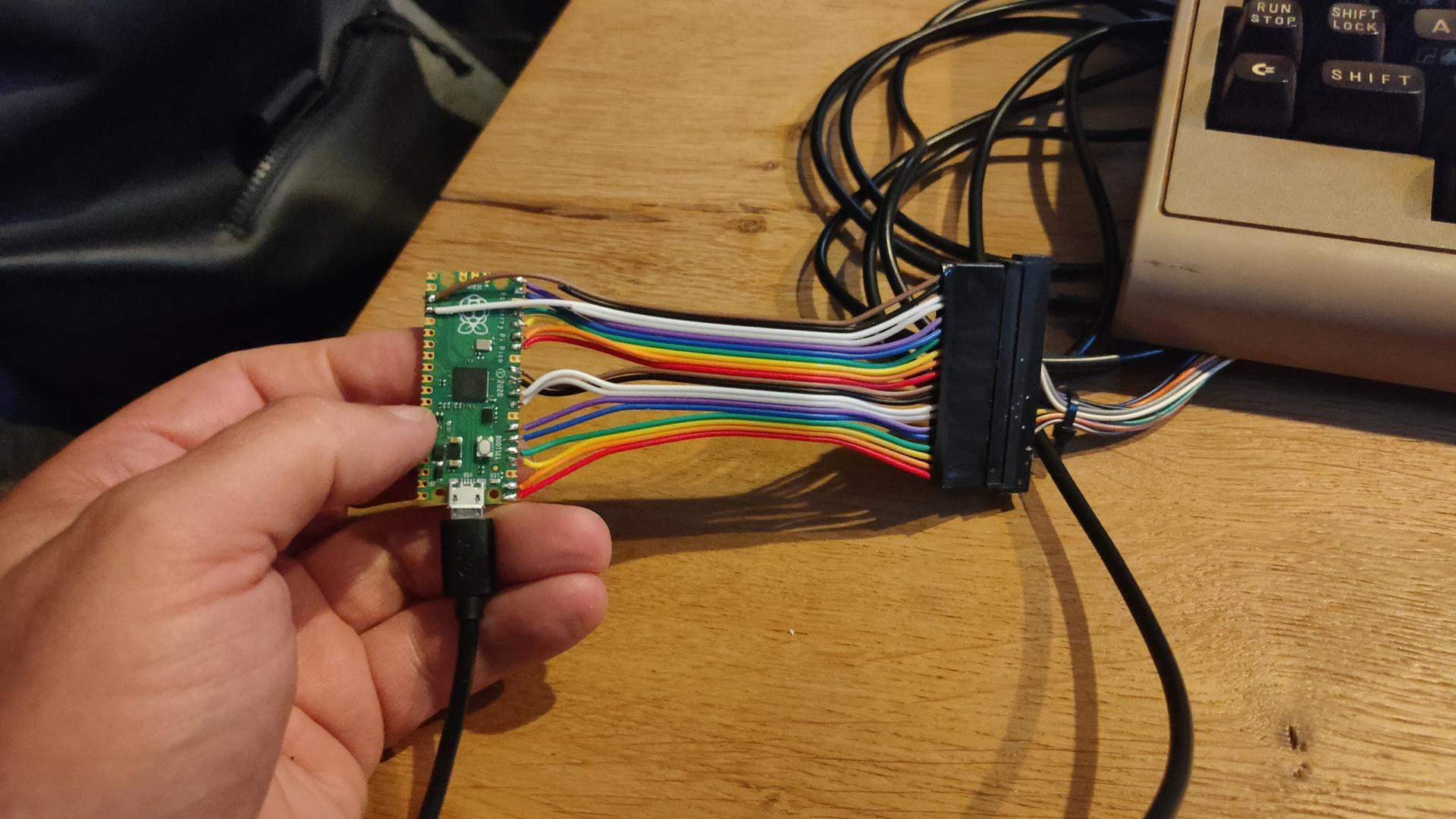
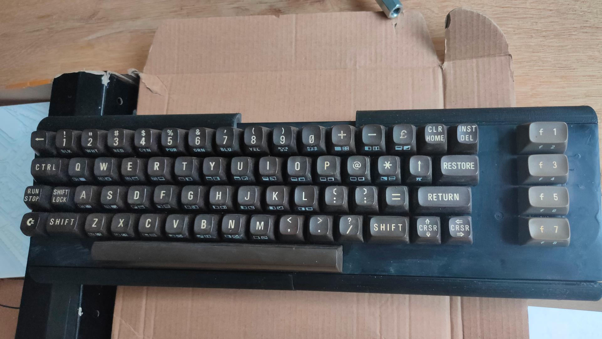
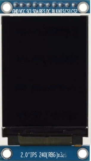
While ordering components for a mini C64 project I’m doing with my friend Bigred, I ordered a cheap ST7789-v2 display.
I want to make a generic pico gadget with a display, buttons and sound. This to make a mini device for writing micropython demos.
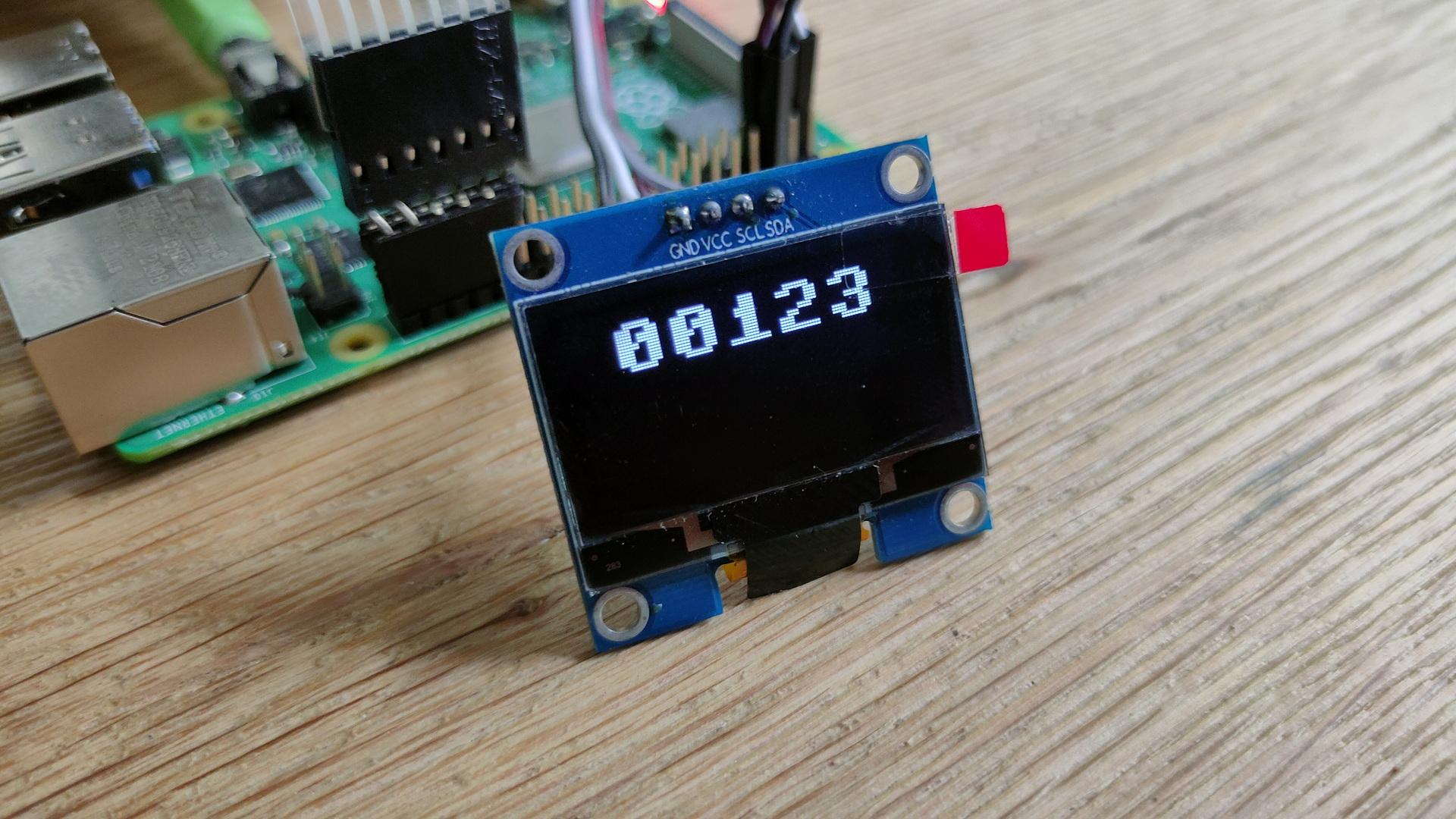
The 3 tactical buttons are controlling the X,Y and Z axis of the rotating Cube.
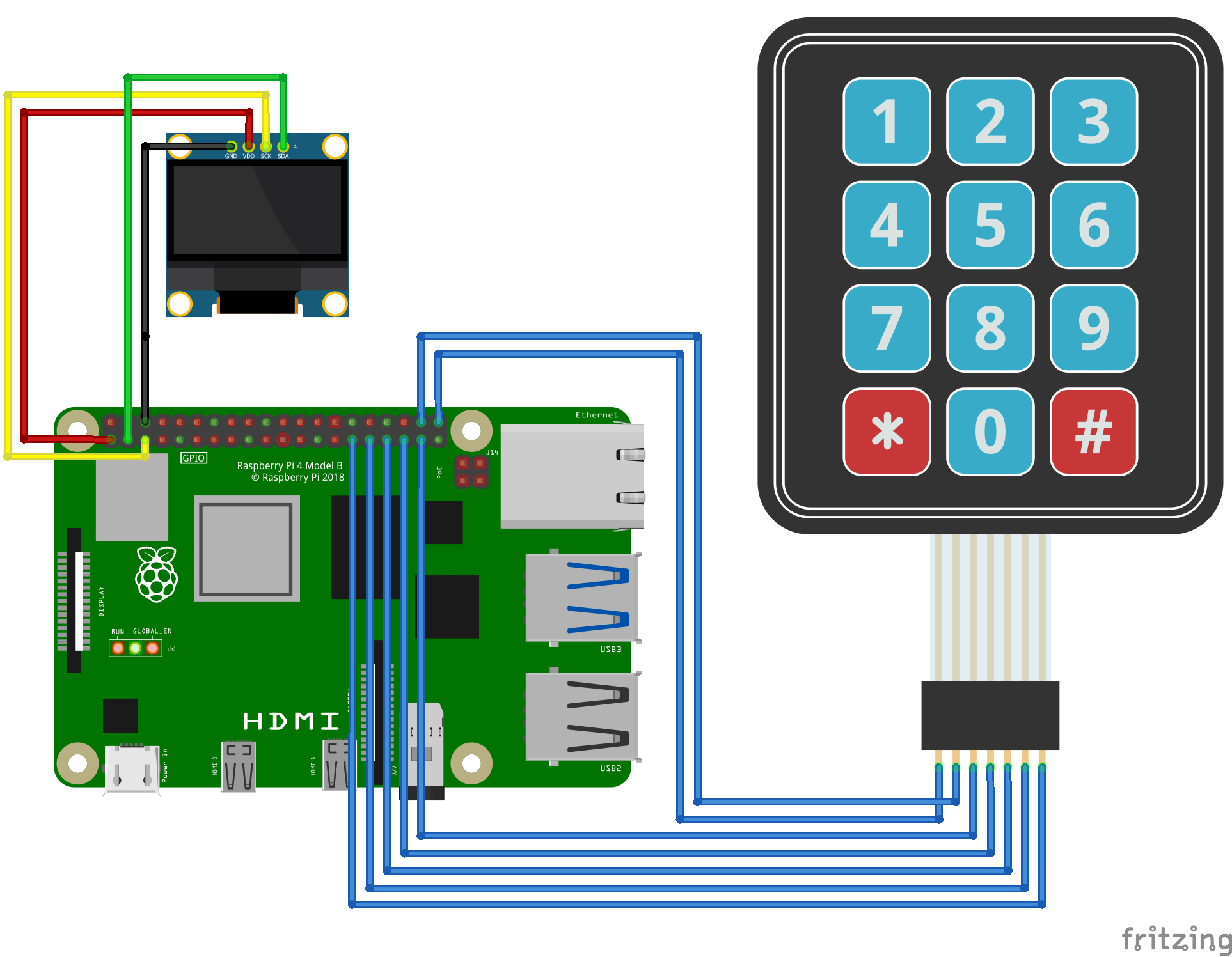
Pinout:
PICO
DISPLAY
GP2
Tactical switch (other side to 3v3)
GP3
Tactical switch (other side to 3v3)
GP4
Tactical switch (other side to 3v3)
GP9
CS1
GND
GND
3v3
VCC
GP18
SCL (SPI clock)
GP19
SDA (MOSI / SPI Data)
GP20
RES (reset)
GP17
DC (data command)
GP16
BLK (backlight)
I know it says SCL/SDA (i2c) but it’s SPI controlled.
Used library : https://github.com/russhughes/st7789_mpy/tree/master
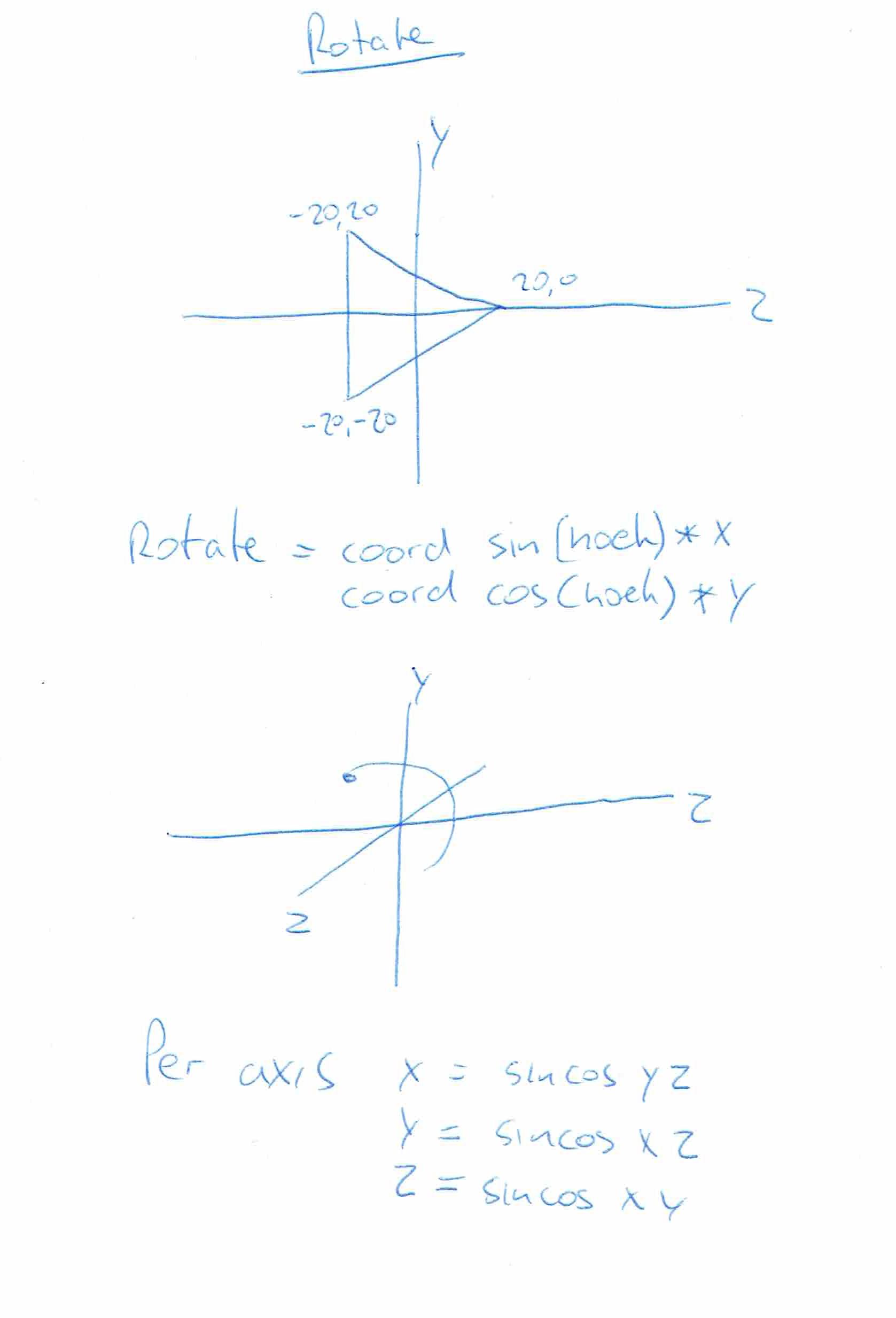
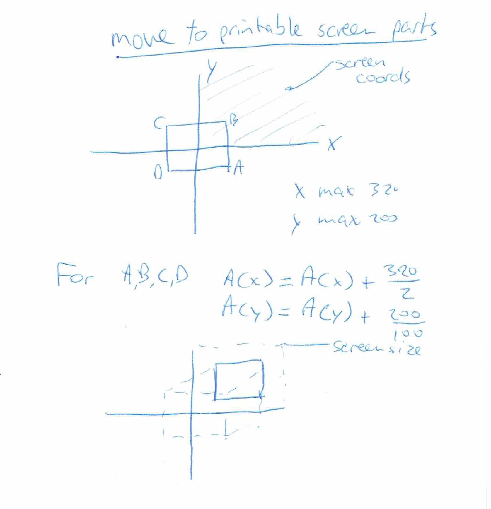
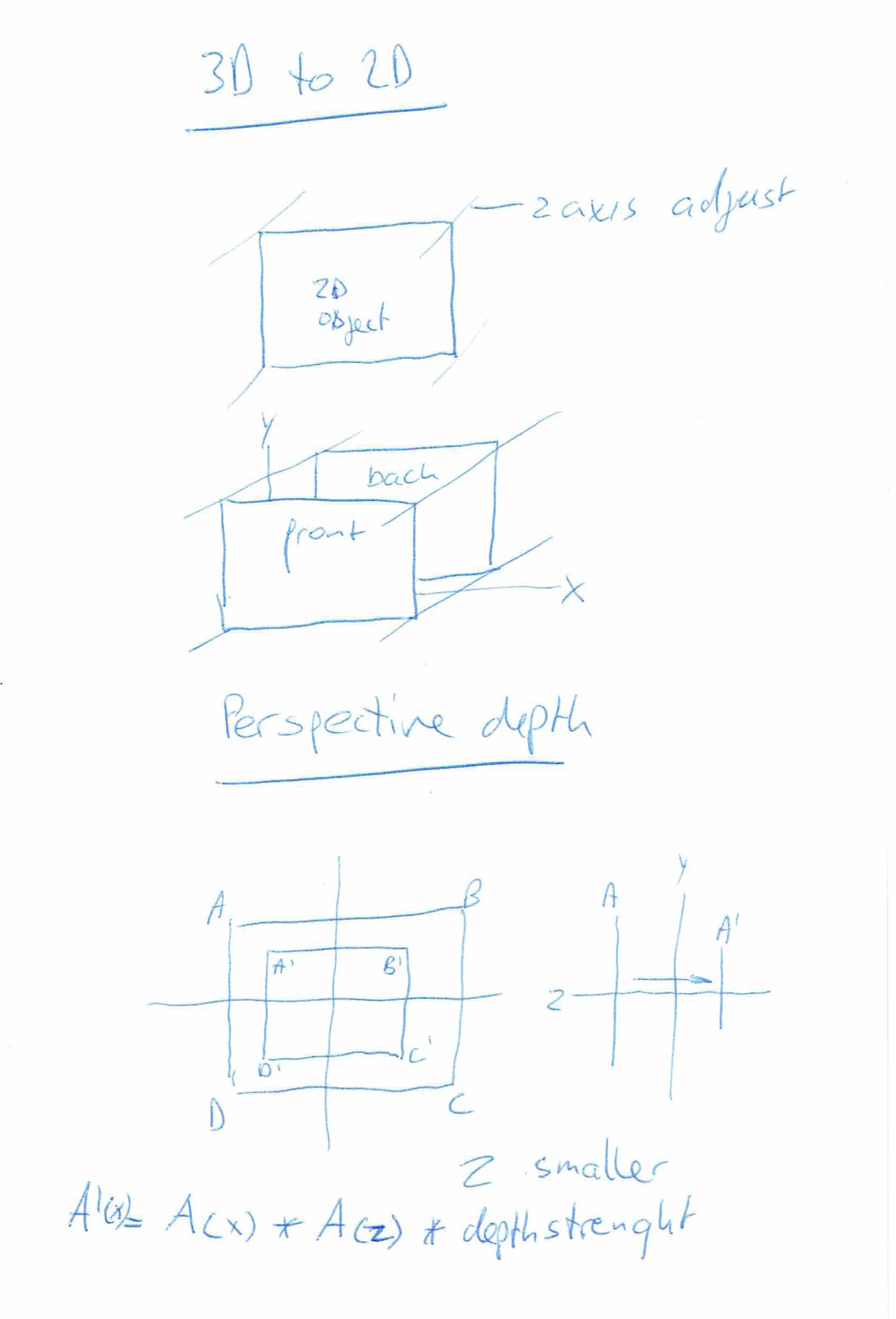
Some 3D explanation I drew a long time ago.
Using python you can use the Math funtions. (sin/cos) Note: these are in radians! print(math.sin(math.radians(30))) # 30 degrees
When using MachineCode you can use lookup tables. These are generated tables which hold precalculated sin data for every degree. You don’t have to use both cos and sin! (these are just 90 degrees shifted!)
Erik and I used a little basic program to generate an ASM include file like this
Costab LABEL BYTE
DB 0B4h,0B4h,0B4h,0B4h,0B4h,0B3h,0B3h,0B3h,0B2h,0B2h,0B1h,0B1h,0B0h,0AFh,0AFh
DB 0AEh
DB 0ADh,0ACh,0ABh,0AAh,0A9h,0A8h,0A7h,0A6h,0A5h,0A4h,0A2h,0A1h,0A0h,9Eh,9Dh,9Bh
DB 9Ah,98h,96h,95h,93h,91h,90h,8Eh,8Ch,8Ah,88h,86h,84h,82h,80h,7Eh
DB 7Ch,7Ah,78h,76h,74h,72h,70h,6Eh,6Ch,69h,67h,65h,63h,61h,5Eh,5Ch
DB 5Ah,58h,56h,53h,51h,4Fh,4Dh,4Bh,48h,46h,44h,42h,40h,3Eh,3Ch,3Ah
DB 38h,36h,34h,32h,30h,2Eh,2Ch,2Ah,28h,26h,24h,23h,21h,1Fh,1Eh,1Ch
DB 1Ah,19h,17h,16h,14h,13h,12h,10h,0Fh,0Eh,0Dh,0Ch,0Bh,0Ah,09h,08h
DB 07h,06h,05h,05h,04h,03h,03h,02h,02h,01h,01h,01h,00h,00h,00h,00h
DB 00h,00h,00h,00h,00h,01h,01h,01h,02h,02h,03h,03h,04h,05h,05h,06h
DB 07h,08h,09h,0Ah,0Bh,0Ch,0Dh,0Eh,0Fh,10h,12h,13h,14h,16h,17h,19h
DB 1Ah,1Ch,1Eh,1Fh,21h,23h,24h,26h,28h,2Ah,2Ch,2Eh,30h,32h,34h,36h
DB 38h,3Ah,3Ch,3Eh,40h,42h,44h,46h,48h,4Bh,4Dh,4Fh,51h,53h,56h,58h
DB 5Ah,5Ch,5Eh,61h,63h,65h,67h,69h,6Ch,6Eh,70h,72h,74h,76h,78h,7Ah
DB 7Ch,7Eh,80h,82h,84h,86h,88h,8Ah,8Ch,8Eh,90h,91h,93h,95h,96h,98h
DB 9Ah,9Bh,9Dh,9Eh,0A0h,0A1h,0A2h,0A4h,0A5h,0A6h,0A7h,0A8h,0A9h,0AAh,0ABh,0ACh
DB 0ADh,0AEh,0AFh,0AFh,0B0h,0B1h,0B1h,0B2h,0B2h,0B3h,0B3h,0B3h,0B4h,0B4h,0B4h
CosTabE LABEL BYTE


Basic:
0 DEF SEG = &H7000: c = 0
1 pi = 3.14159265#
2 FOR x = 0 TO 2 * pi STEP 2 * pi / 256
3 d = COS(x) * 127 + 127
4 POKE c, d: c = c + 1: NEXT
Most i learned from a book called “Art of Graphics” (This is image of the book from the internet, i don’t think I still got my copy somewhere.
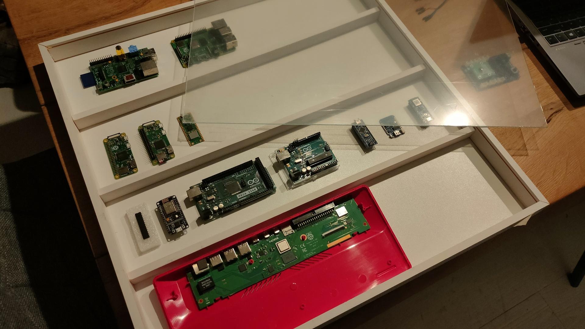
I started a little case for a collection of Raspberry devices.
Over the years, many Raspberries were designed and made. It all started in 2012 I want to have a case with all RP’s i’ve used.
There are many iterations of the RPi, I’m missing a lot now. If you want to help me, send me old/broken raspberries to get the collection complete!
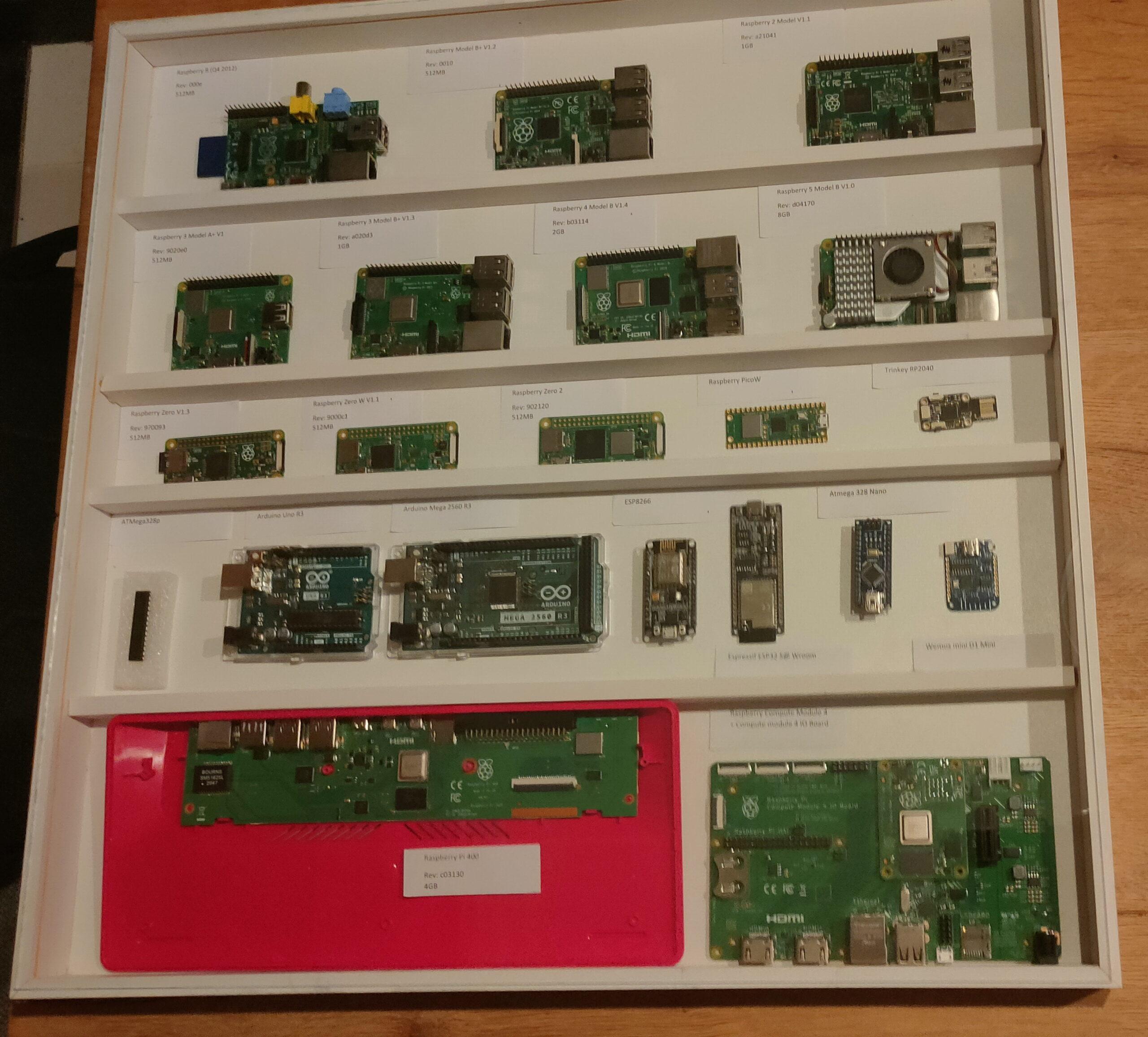
This is the case at the moment
Case with some Raspberries and Arduino’s I found lying around, I’m not going to dismantle projects. Only the RPi 1A, 4B, Zero, Zero W, Pico and RPi 400 are displayed. Plastic sheet as protective layer still on there, should be clear as glass.
The case isn’t glued together yet. I’m not sure how and what to include.
Horizontal wooden bars to place the devices on?
Include a history of Arduino’s for now?
Put little notes in the case with information? Like my SDK-85 case?