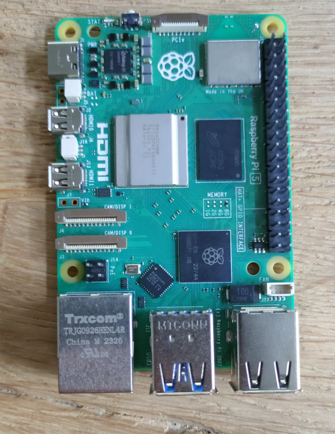
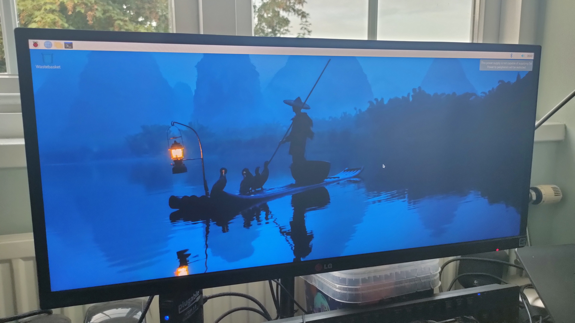
So many things to try .. and probably buy. I’m lucky to have this already, official it’s not even out yet.
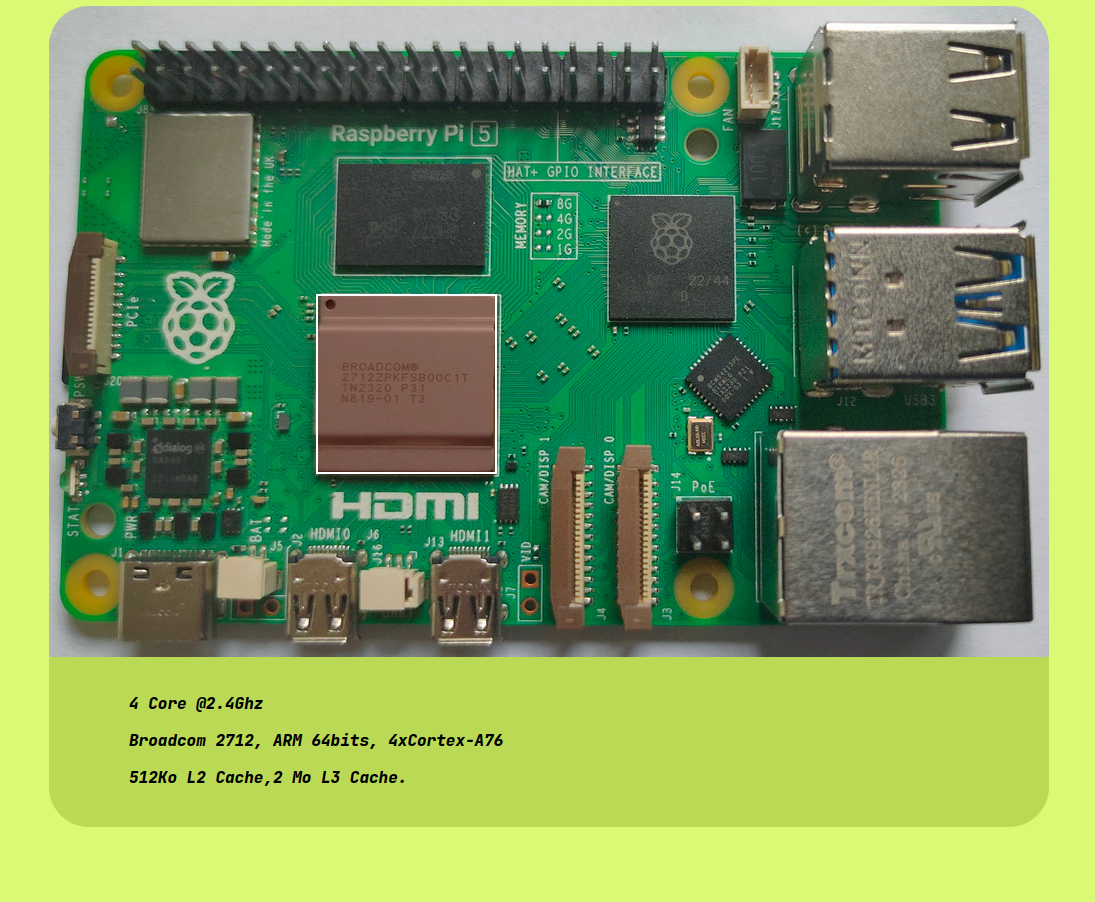
Specification
Processor : Broadcom BCM2712 2.4GHz quad-core 64-bit Arm Cortex-A76 CPU, B with cryptography extensions, 512KB per-core L2 caches, and a 2MB shared L3 cache
Features:
VideoCore VII GPU, supporting OpenGL ES 3.1, Vulkan 1.2
Dual 4Kp60 HDMI® display output with HDR support
4Kp60 HEVC decoder
LPDDR4X-4267 SDRAM (4GB and 8GB SKUs available at launch)
Dual-band 802.11ac Wi-Fi
Bluetooth 5.0 / Bluetooth Low Energy (BLE)
microSD card slot, with support for high-speed SDR104 mode
2 × USB 3.0 ports, supporting simultaneous 5Gbps operation
2 × USB 2.0 ports
Gigabit Ethernet, with PoE+ support (requires separate PoE+ HAT)
2 × 4-lane MIPI camera/display transceivers
PCIe 2.0 x1 interface for fast peripherals (requires separate M.2 HAT or other adapter)
5V/5A DC power via USB-C, with Power Delivery support
Raspberry Pi standard 40-pin header
Real-time clock (RTC), powered from external battery
Power button
Some things come to mind to test:
Kubernetes
Dual Camera OpenCV – depthmap and more
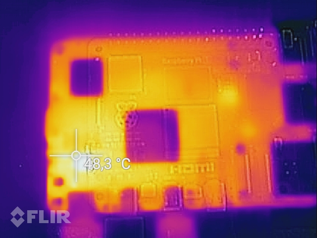
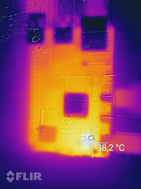
The offset between the normal camera and the Flir, is due to being to close to the object.After 5 minutes Wifi/Bluetooth bottom left heats up (didn’t use in this test)
You really want to use a case with an active blower to cool the rpi.
Busy day: I’ve airbrushed some 3D pieces a few days ago, but i need 50 or so more. Meanwhile is was reinstalling octoprint, and making a new version of my Bluetooth page flipper. (Android Music Sheet Pedal Thingy. Which i also didn’t post apparently) But the main project was this:
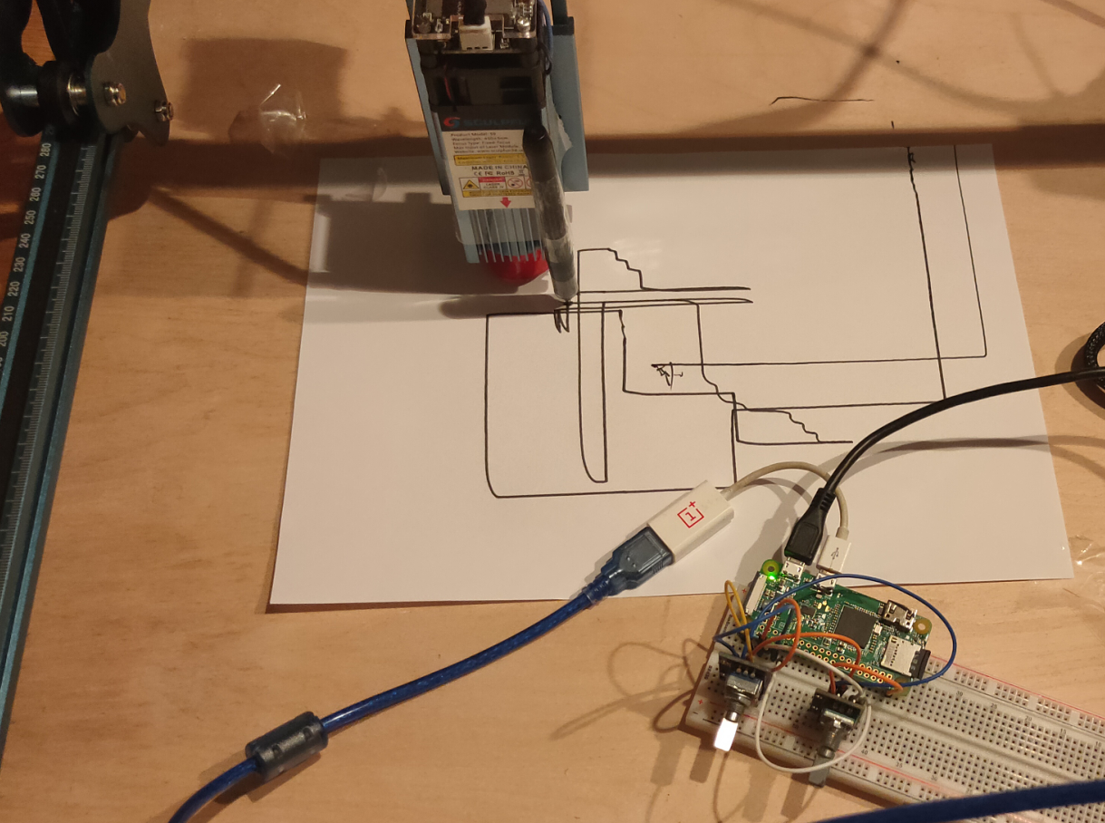
I was curious how fast the stepper motors are on my laser cutter. And for what can we utilize this!
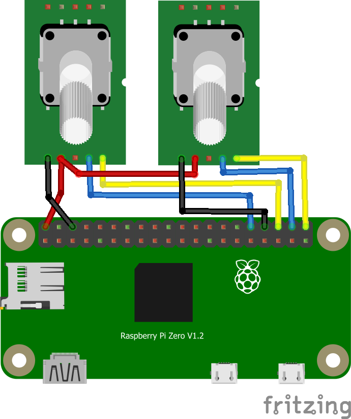
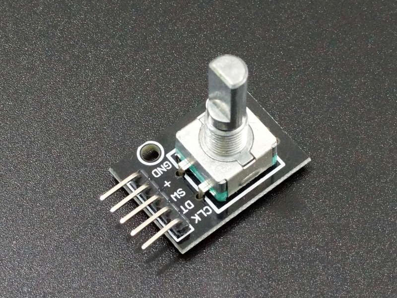
So I took a Raspberry Zero and some rotary encoders, lets make an etch-a-sketch like thingy.
Some rotary encoder modules I had.
Next to do: 3D print a pen holder, and alter the code to enable the laser when moving!
CODE
Below code uses a simple rotary class, and generates control GCodes for the steppers/Sculpfun
import time
import serial
import RPi.GPIO as GPIO
from encoder import Encoder

def valueChanged(value, direction):
    print("* New value: {}, Direction: {}".format(value, direction))

GPIO.setmode(GPIO.BCM)

e1 = Encoder(20, 21, valueChanged)
e2 = Encoder(16, 12, valueChanged)

x = 0
y = 0
arduino = serial.Serial('/dev/ttyUSB0', 115200, timeout=.1)

newx = 0
mystringx = ""
newy = 0
mystringy = ""

arduino.write(str.encode("G00 G17 G40 G21 G54\r\n"))
arduino.write(str.encode('G90\r\n'))
arduino.write(str.encode('M4\r\n'))
arduino.write(str.encode('M8\r\n'))
arduino.write(str.encode('G0 X41.5Y36.05\r\n'))
arduino.write(str.encode('M3\r\n'))
#arduino.write(str.encode('G91\r\n'))
arduino.write(str.encode('G1 X2.5F6000S0\r\n'))
arduino.write(str.encode('G1 X0\r\n'))
arduino.write(str.encode('G1 Y0\r\n'))

try:
    while True:
        data = arduino.readline()[:-2] #the last bit gets rid of the new-line chars
        if data:
                print (data)
        arduino.write(str.encode("G1 F10000\r\n"))
        newx=e1.getValue() *5 + 100
        newy=e2.getValue() *5 + 100
        mystringx=f"G1 X{newx}\r\n"
        mystringy=f"G1 Y{newy}\r\n"
#        print(mystringx)
        arduino.write(str.encode(mystringx))
        arduino.write(str.encode(mystringy))

except Exception:
    pass

GPIO.cleanup()
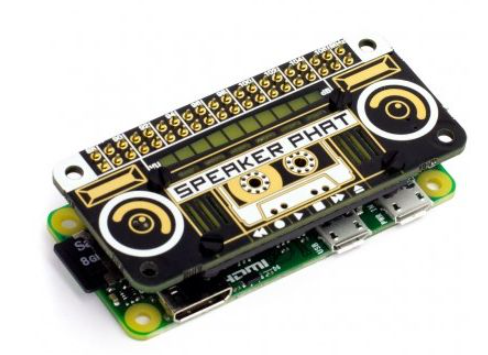
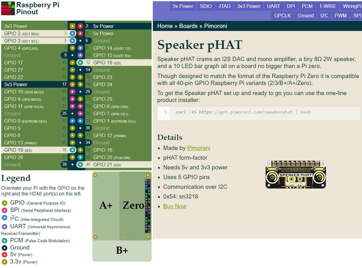
I’ve got an old Speaker Phat, and a Raspberry Zero
An audio add-on board for Raspberry ( same size as the Zero )
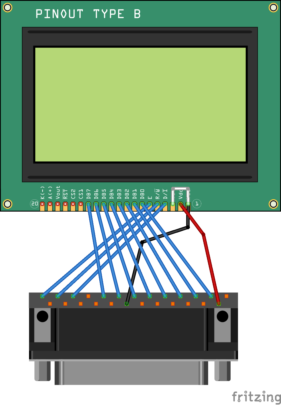
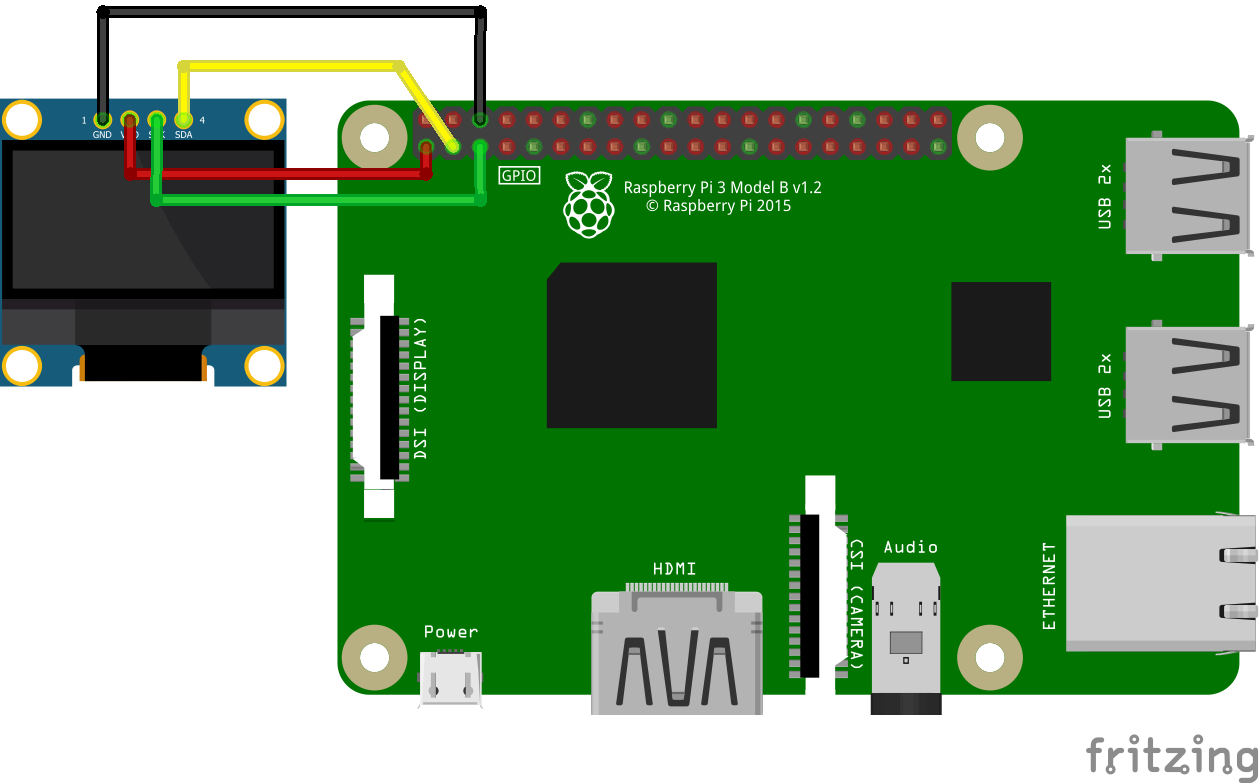
Connections
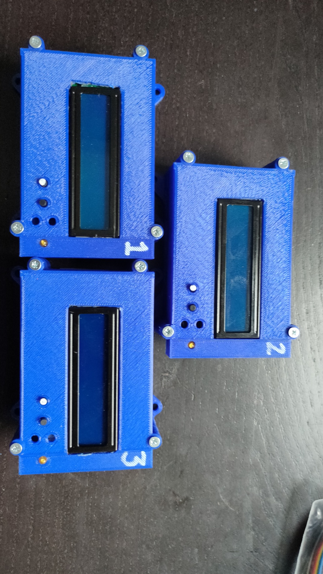
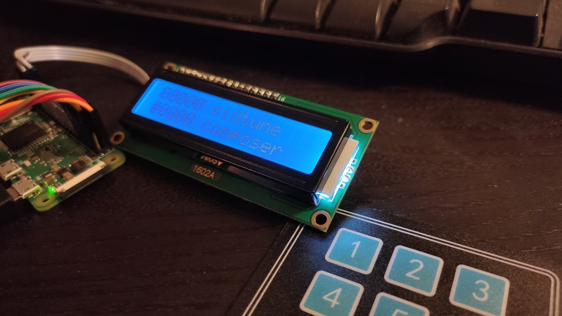
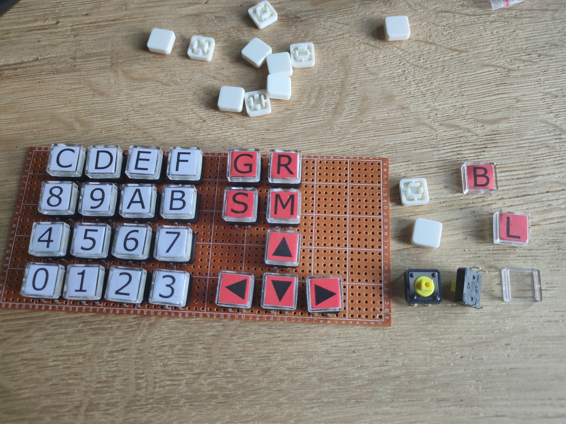
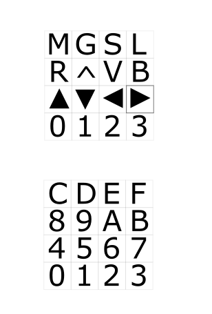
My initial idea was to have the “High Voltage Sid Collection” (Downloaded the 55000 pack) On a mini device, battery operated and with a little keypad.
On the keypad i can select the Sidtune to play, or pressing A and a number the Sids from a certain artist.
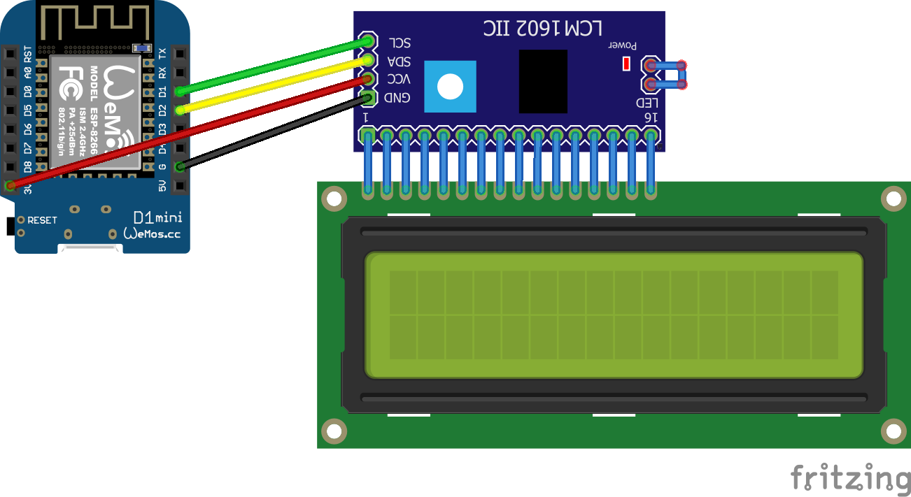
The display gives you information about the tune being played. ( The display has an I2C hat to convert 8bits to I2C )
See pinout phat above. I’ve got three choices for I2C connection (green/blue to the Phat)
Direct connect and use different addresses
Use a I2C hub and different addresses
Define a secondary I2C on the raspberry
So I made the first test setup …
Underrun occurred .. So back to the drawingboard. I probably need a better Audio Hat. First to try .. Zero fast enough for sidplay2? Maybe audio over hdmi works??
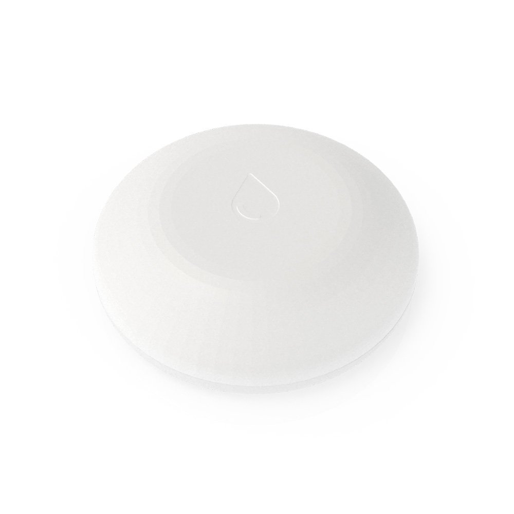
I’ve had this Shelly sensor for a long time. But never posted anything about this. Last weekend we had a -situation- in our kitchen, so what better time to test this device again!
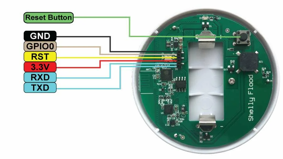
This little disc shaped device has three metal points on its bottom side, those are the flood (water) sensors. It stay’s in sleep mode when all’s good. It does several things when it detects water.
Emits a alarm signal
Wakes-up wifi
Sends a MQTT message (when not connected to the cloud like i have) MQTT is a alarm message AND it wil send the temperature of the device!
After a while (when dry) goes back to sleep
There are connection point on the print you can use .. happy hacking!
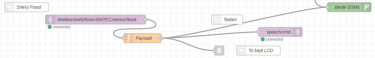
My node-red configuration
Above is the part where the mqtt messages gets processed by Node-Red Sending it to PushOver and my little MqttLcdNotifier
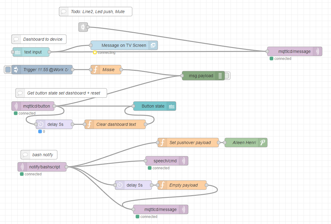
Above is the MqttLcdNotifer .. there are several parts to this
Top line is from shelly flood and other notifications
Text input puts text from the NR GUI on my TV and the LCDDisplay
same parts are being used by my 3D printer when the print tool is getting TO hot, or printing is finished
Trigger at work WAS a notification for work .. nonfunc
mqttlcd-button is the mqtt message send from the display (the one that i was pushing) to stop the beeping and clears the display
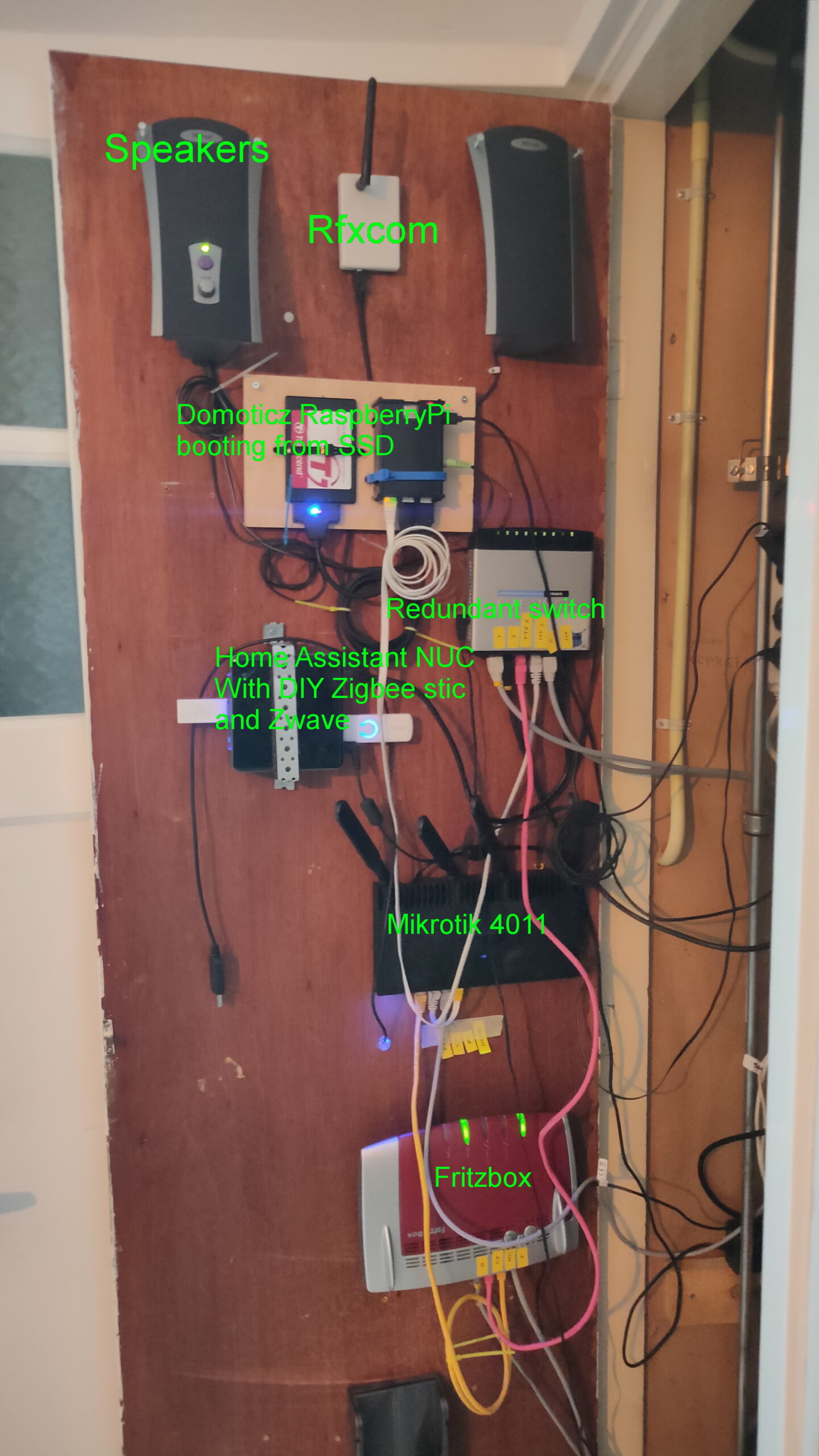
Bash notify, is as previously posted a flow which i can control from my linux machines notify “compiling complete” for example. This is also being broadcast from my livingroom using speakers. (See separate post about this)
Wellll, put this in place 2 years ago, never looked at it again .. still works
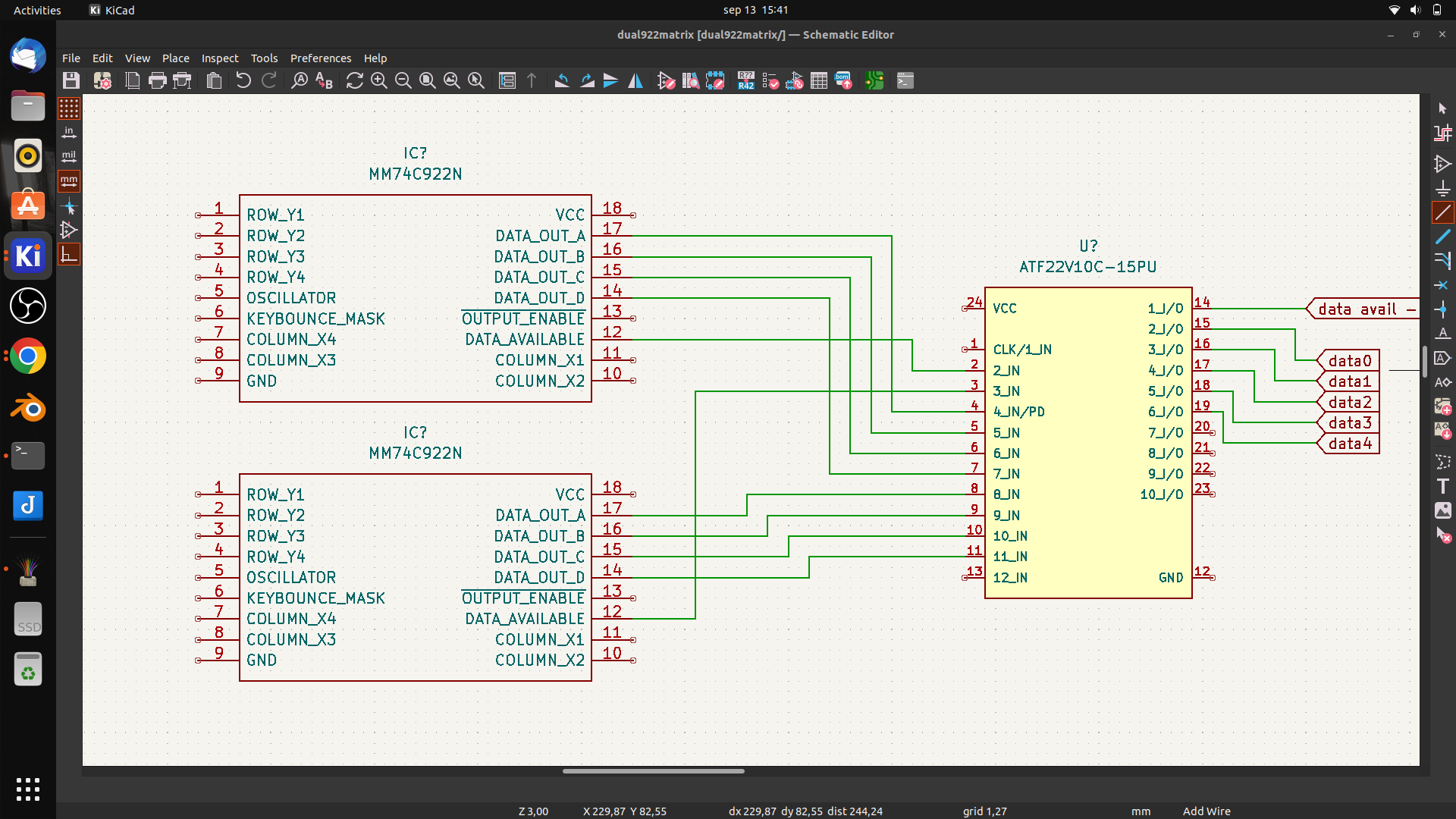
In this case designed for my 6502, but it is a generic setup.
I it just a dual 16key matrix decoder merged together. You can probably use this with raspberries, arduinos etc.
I wanted to use 74C923 but these are nowhere to be found. And even then, the number of keys wil be 20. So i am tying together two 74C922 using some logic in a PLD.
First draft
It wil be something like above. Using the data availabe signal i can combine both 16key matrixes. (In theory .. it is all untested)
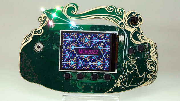
Almost … friday will be the day i’ll attend May Contain Hackers. Besides the awesome villages and talks.
UPDATE: 20220727 UPDATE: 20220812
You get a hackable badge, this one is more amazing as previous versions.
I can’t wait to have a go at this cool gadget. I personally could do without the pcb fancy design.
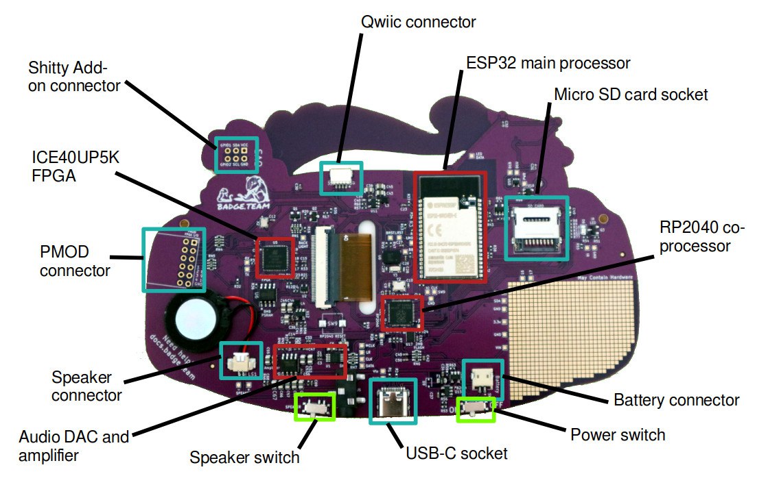
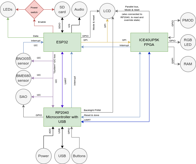
Espressif ESP32 Wrover-E with 16MB of flash storage and paired with 8MB of PSRAM, for front-end badge computing and compatibility with the badge.team ecosystem back to the 2017 SHA badge.
Lattice ICE40UP5K FPGA for hardware-accelerated graphics and user FPGA hardware designs.
Raspberry Pi RP2040 for advanced USB communication and board management.
2Ah LiPo battery to give you a full day of fun on a charge.
16-bit DAC with stereo output to headphone socket, onboard mono speaker.
ILI9341 2.2 inch TFT display with a 240 by 320 pixel resolution.
Bosch BNO055 orientation sensor.
Bosch BME680 environmental sensor.
The usual array of addressable LEDs.
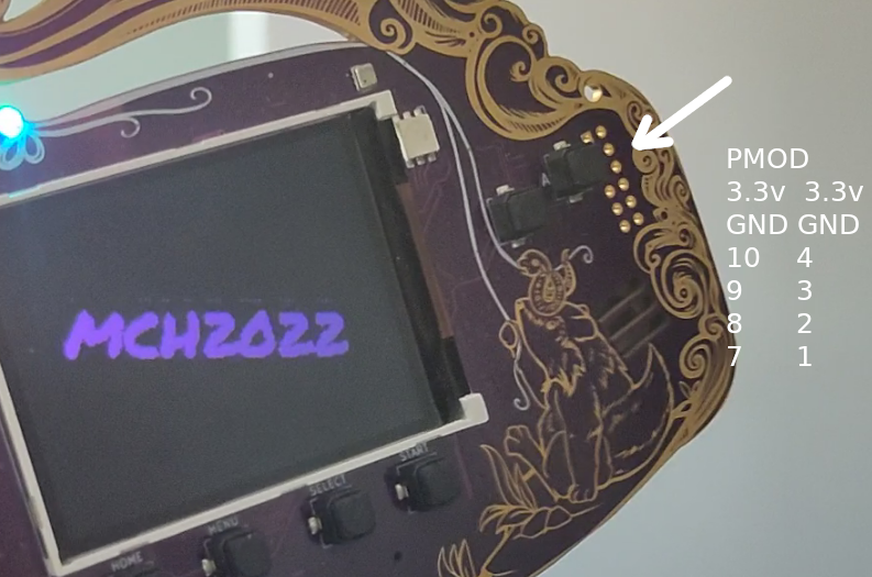
SAO and Qwiic expansion connectors, FPGA PMOD expansion, plus onboard prototyping area.
Downloadable apps, micro python, Arduino ide programming. All kinds of GPIO pins, leds buttons, sound. Check out https://hatchery.badge.team/
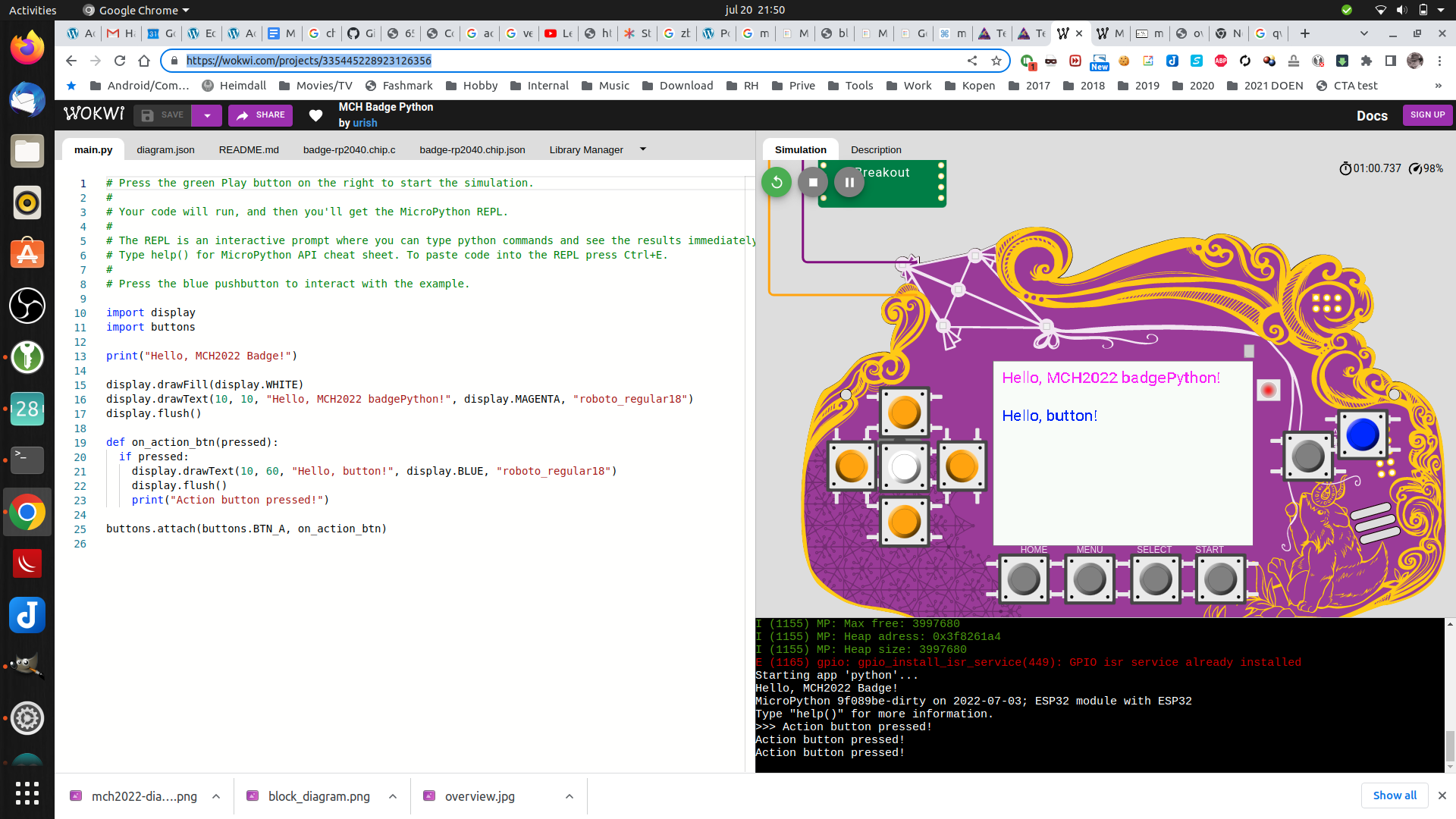
You can play with this virtually here! https://wokwi.com/projects/335445228923126356
So much potential! Great start for a DIY project.
I won’t post about the workings, thats all well documented online. I shall post about the hacks/findings i personally did.
UPDATE: 20220727 Made a micropython program to keep your NameTag level to the ground (Better version)
UPDATE: 20220812
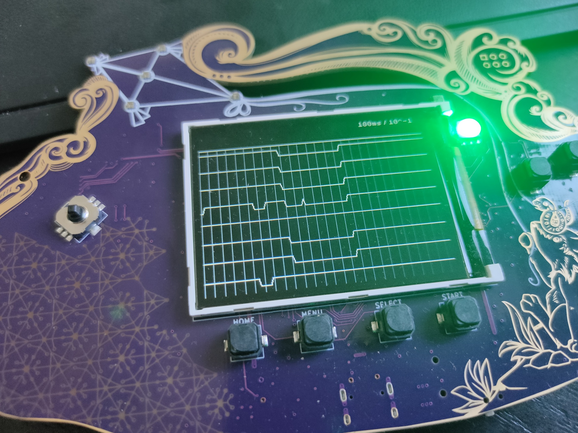
Someone made a 8bit logic analyser using the pmod connector !
Next week i’ll be going to May Contain Hackers 2022, what to bring? My old friend Bigred will be there, many others couldn’t make it …
What to bring and do:
Laptops
Arduino touch project?
My new 6502 breadboard computer?
The DVB-T / DAB / FM stick
Besides the emulators on my laptop, maybe i’ll bring this little thing (Or a real C64?)
Booting in 4 seconds! Running Vice in 50 or 60 Hz Low latency video! Can emulate cartrides, floppy’s When you connect joysticks or a real C64 keyboard to the GPIO pins it will use that. SID sound using ReSid CRT emulation (look for BMC64 or combian)
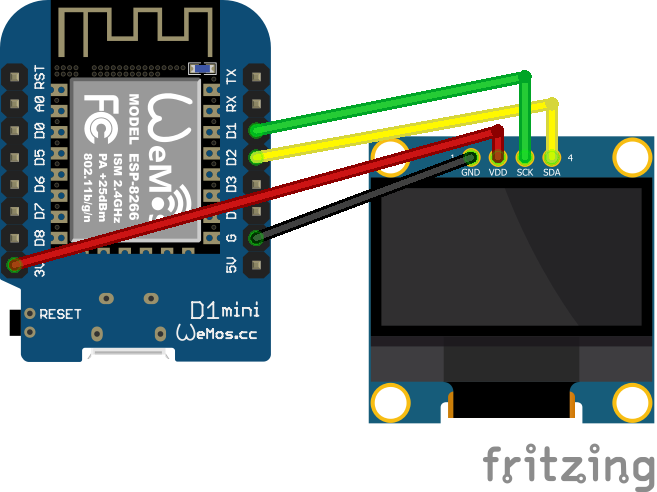
Below some examples and connection diagrams to control displays. More code and complete schematics will be added on this page or on a separate projects page.
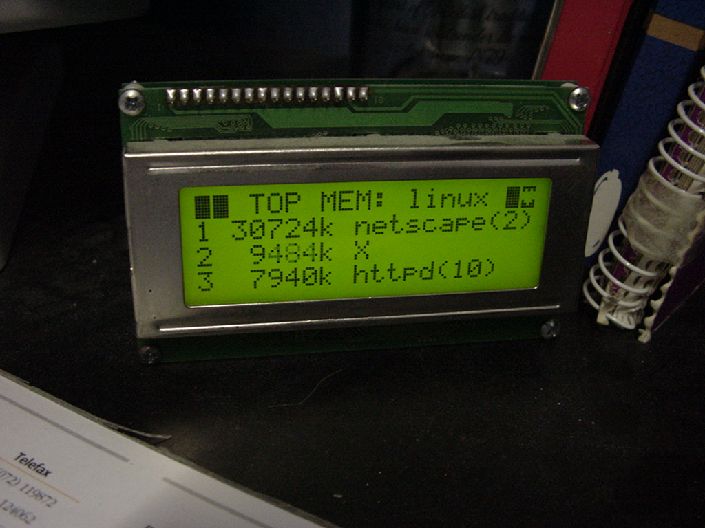
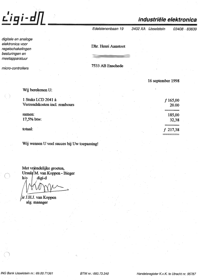
UPDATE 20230119 Cost of 20×4 display in 1998
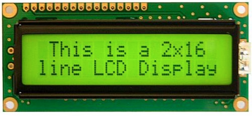
LCD
I’ve used a LCD display like this (HITACHI HD44780) on my PC in the 90s, and also written code to use this as a monitoring device on my amiga.
On Linux i used LcdProc – This module also was equiped with a serial connector
Now (2023) it is 8 euros! When bought now fl to euro 98 Euro or 107 $
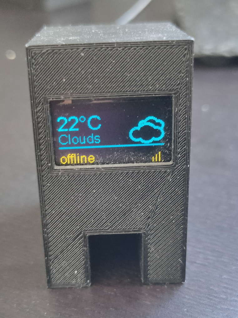
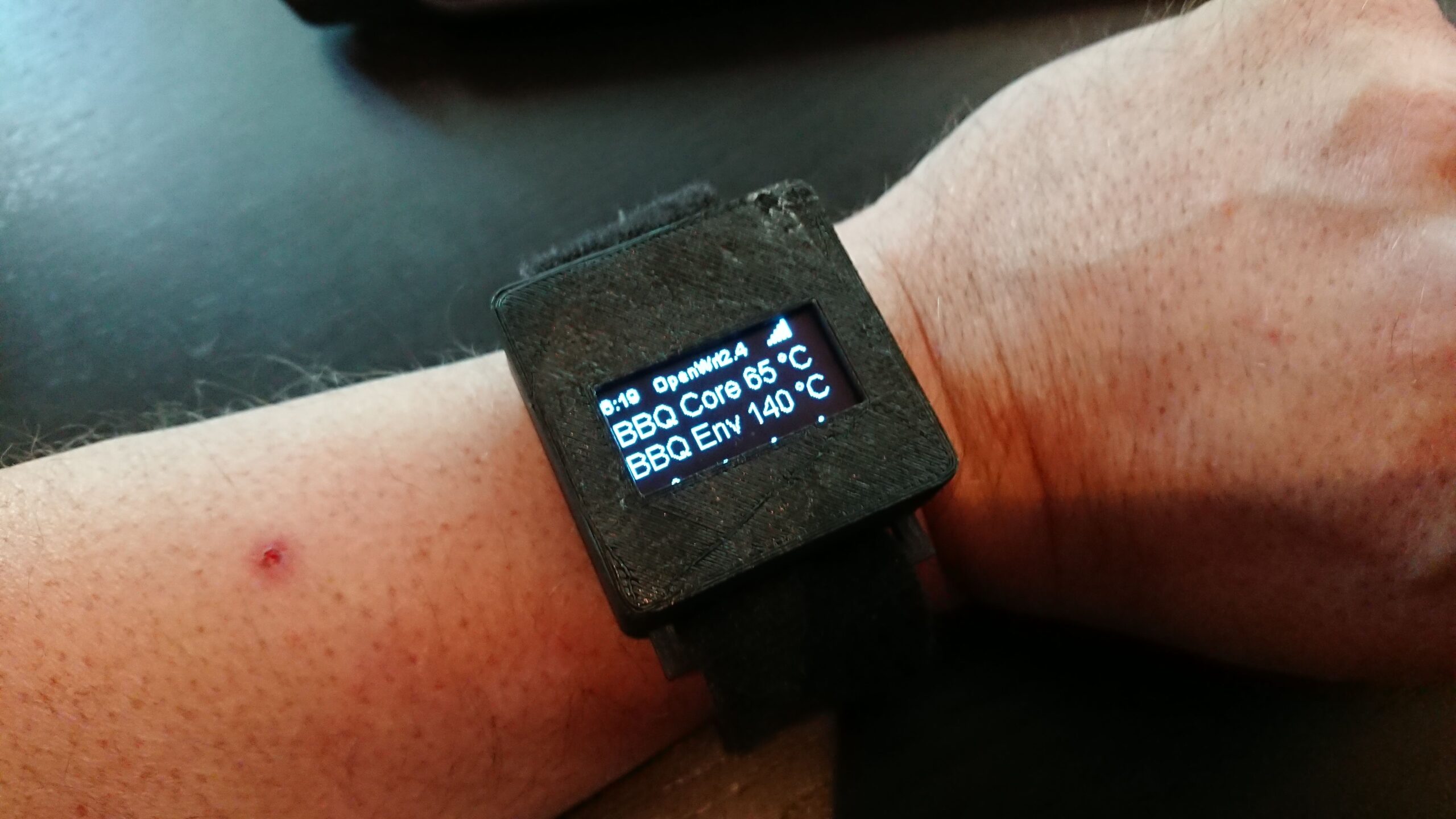
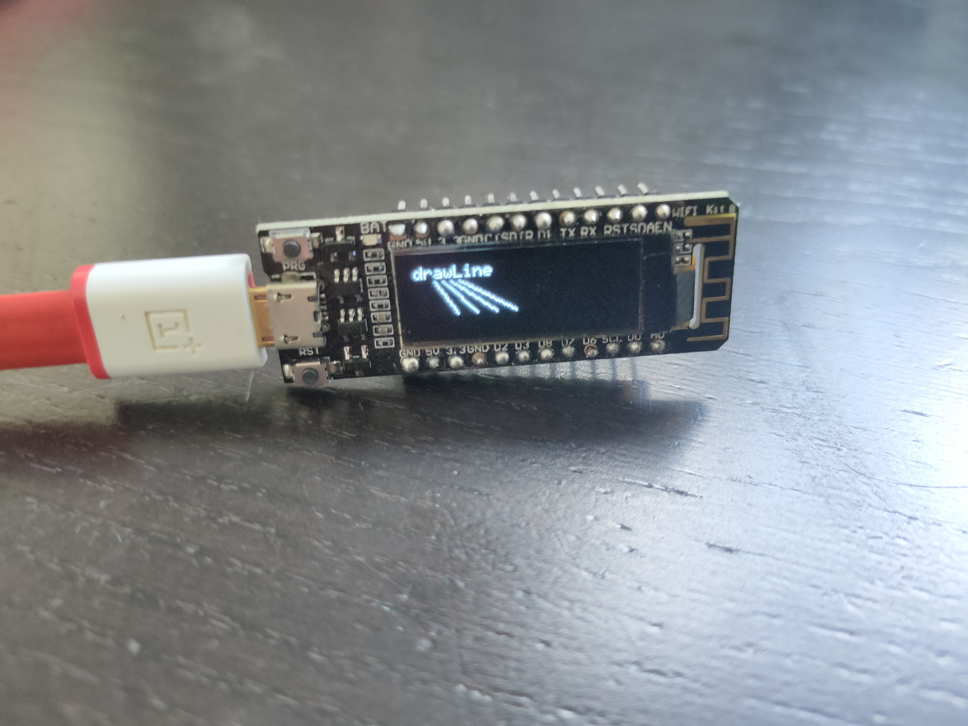
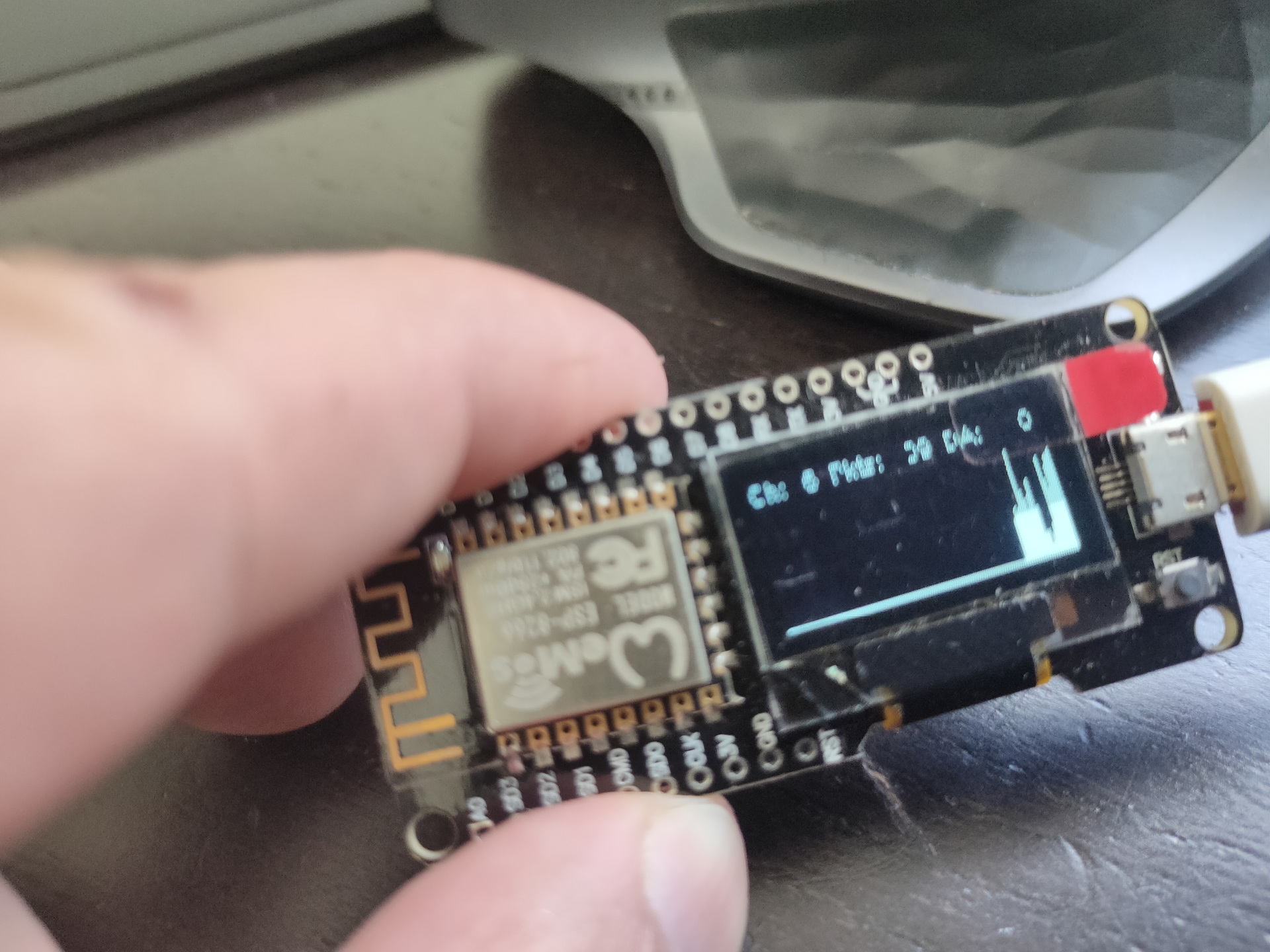
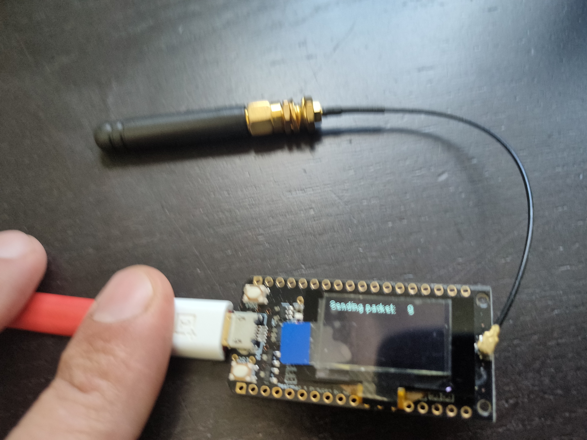
Some arduino’s have embedded displays like those i’ve used for a Lora project.
No usedWifi packet monitorLora test
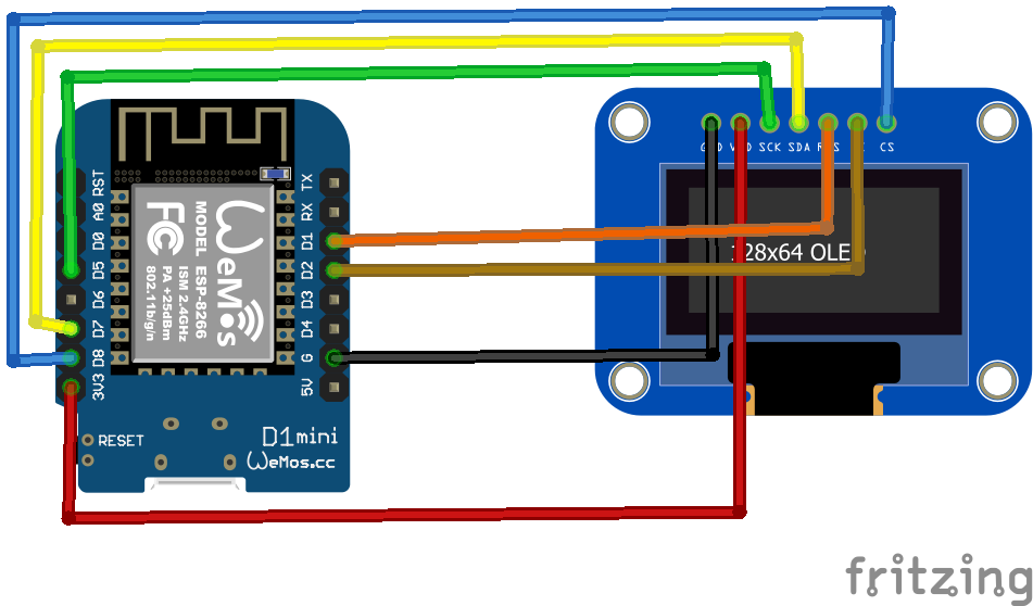
Other means of connecting : SPI
SPI connected display
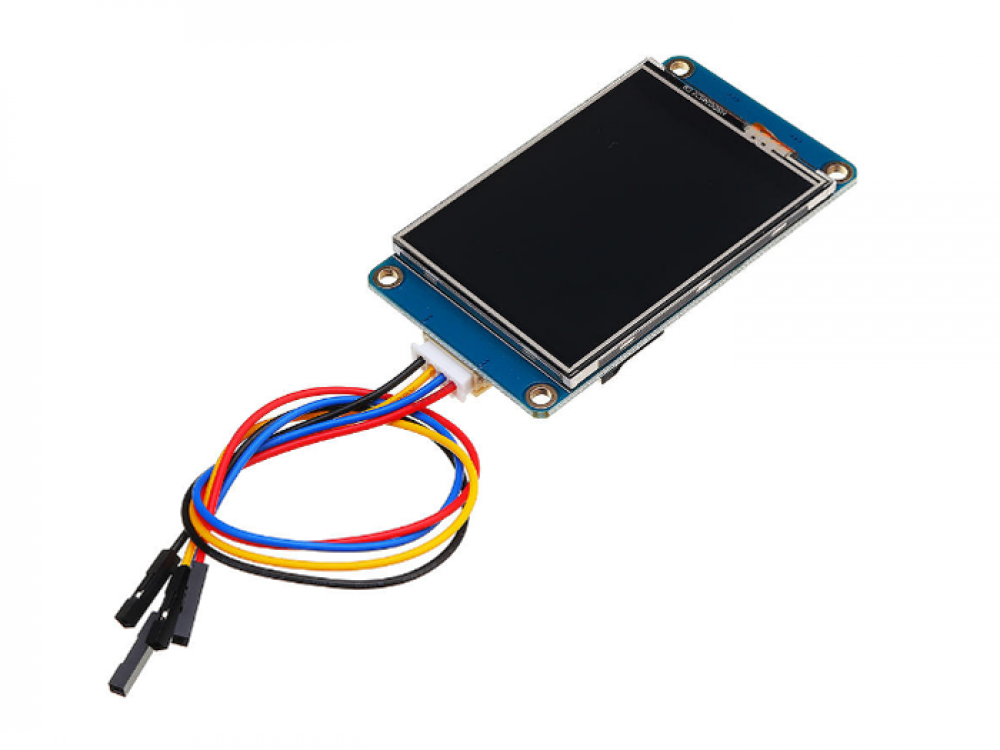
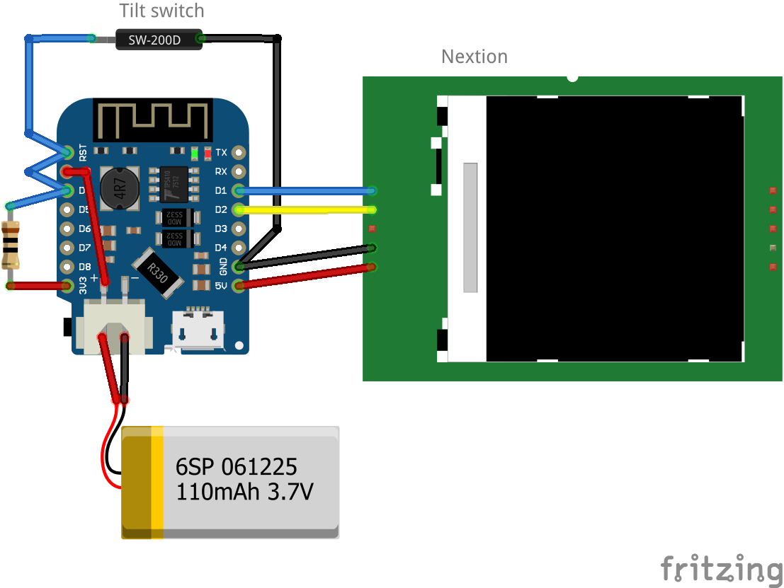
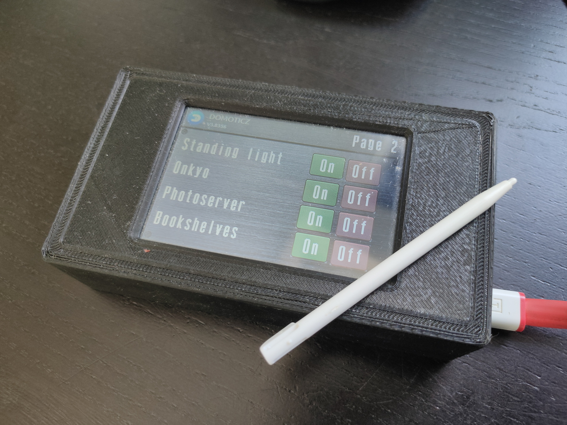
Nextion
Nextion is a Human Machine Interface (HMI) solution combining an onboard processor and memory touch display with Nextion Editor software for HMI GUI project development.
Using the Nextion Editor software, you can quickly develop the HMI GUI by drag-and-drop components (graphics, text, button, slider, etc.) and ASCII text-based instructions for coding how components interact on the display side.
Nextion HMI display connects to peripheral MCU via TTL Serial (5V, TX, RX, GND) to provide event notifications that peripheral MCU can act on, the peripheral MCU can easily update progress, and status back to Nextion display utilizing simple ASCII text-based instructions.
edit cmdline.txt
add "fbcon=map:10 fbcon=font:ProFont6x11 logo.nologo"
at the end
edit config.txt
add between custom comments at the bottom
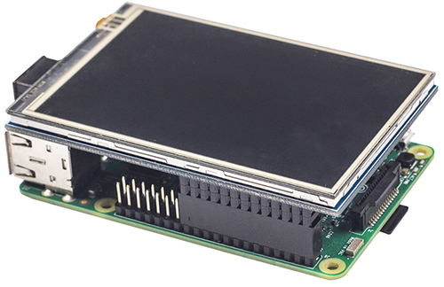
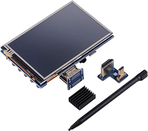
dtoverlay=piscreen,speed=24000000,rotate=90
# Or check http://www.lcdwiki.com/3.5inch_RPi_Display
Above display’s i’ve used for Picore Players and the Lidar POC
To try: Getting above display running with a arduino https://github.com/PaulStoffregen/XPT2046_Touchscreen
Raspberry HDMI display
Easiest of them all, just connect with HDMI, there is a adaptor for hdmi-hdmi (versions 1,2,3) and hdmi-mini-hdmi for RPi4 variants.
Epaper and 7-Segment displays
Other means of displaying information are for example
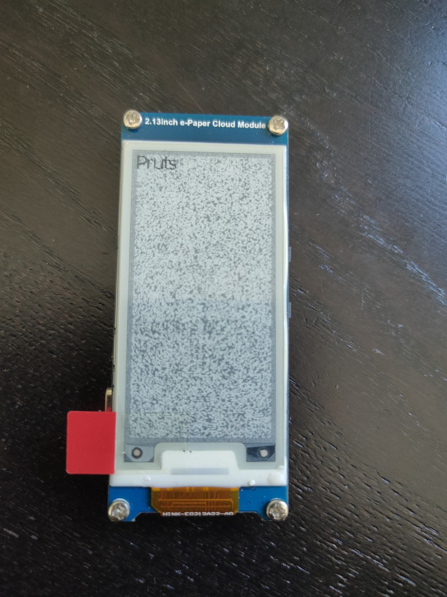
Epaper
ESP with epaper module, disconnected power for a while, artifacts appear.
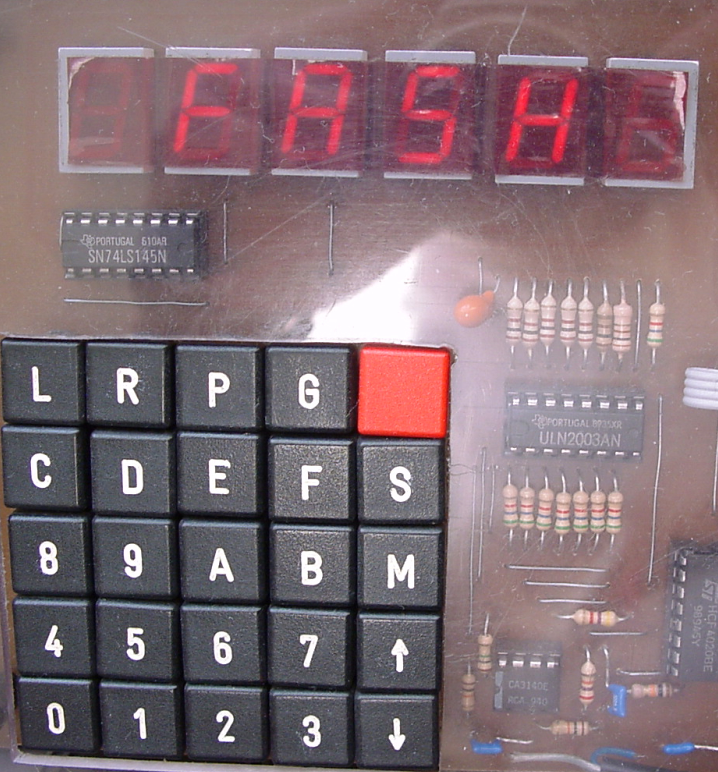
7 Segment displays
I used a lot of 7-Segment display’s in the past. They look cool and are hardcore.
My homebrew computer uses this
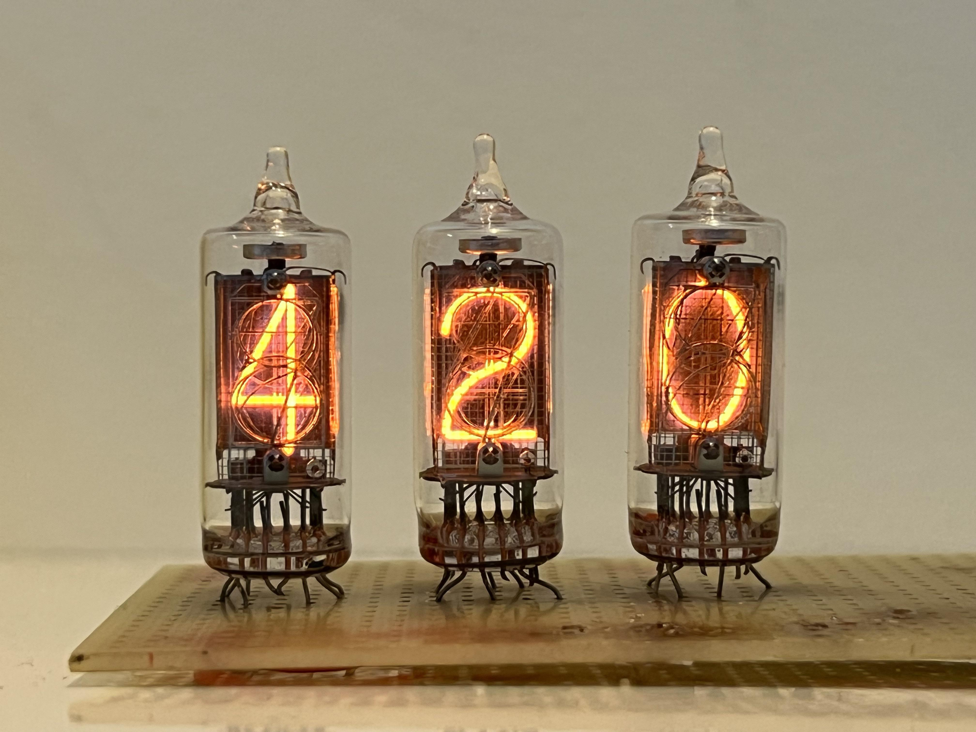
Nixie tubes!
And there are https://en.wikipedia.org/wiki/Nixie_tube .. I’ve never had those
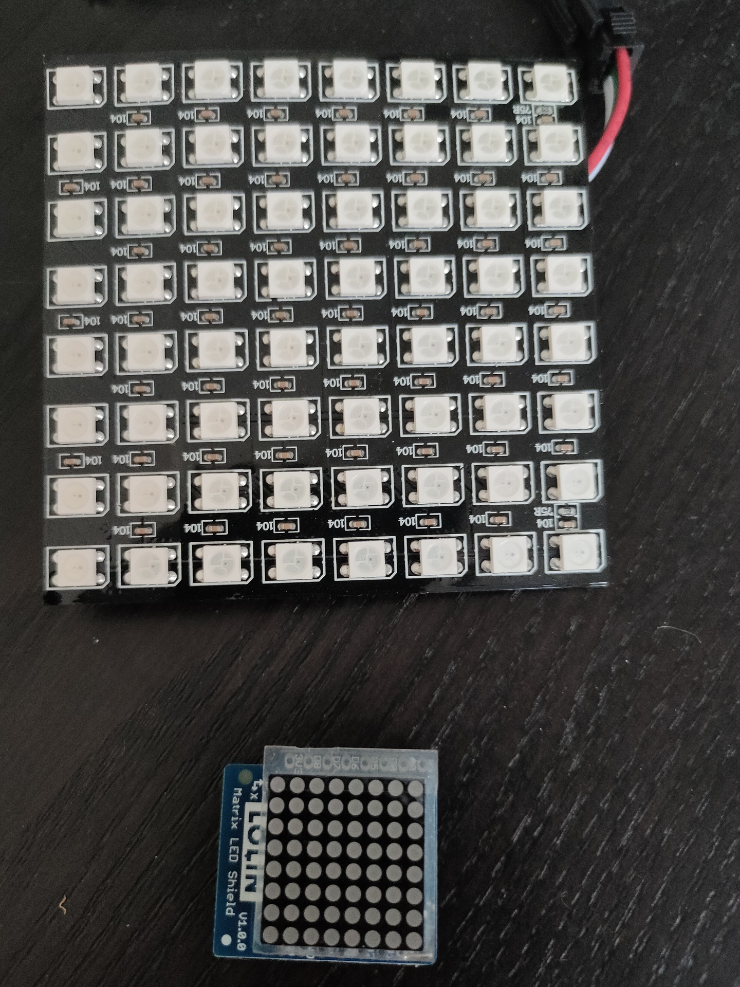
Above bigger 2D display i used with Wled and a digital microphone, so its sound reactive. The lower part i got in recently .
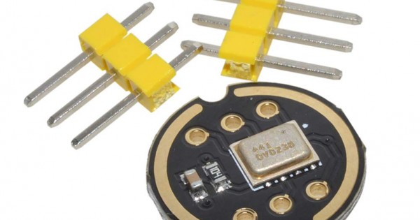
inmp441 digital microphone
"If something is worth doing, it's worth overdoing."