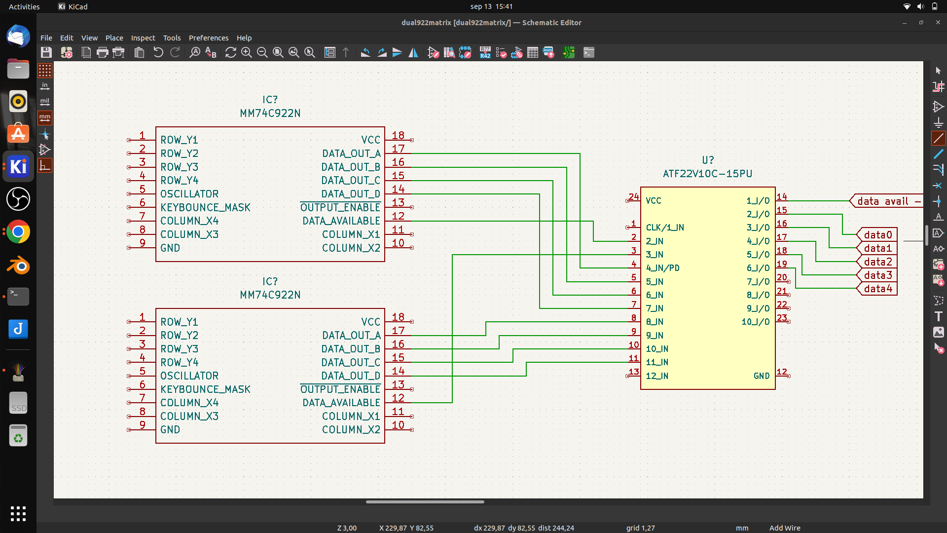
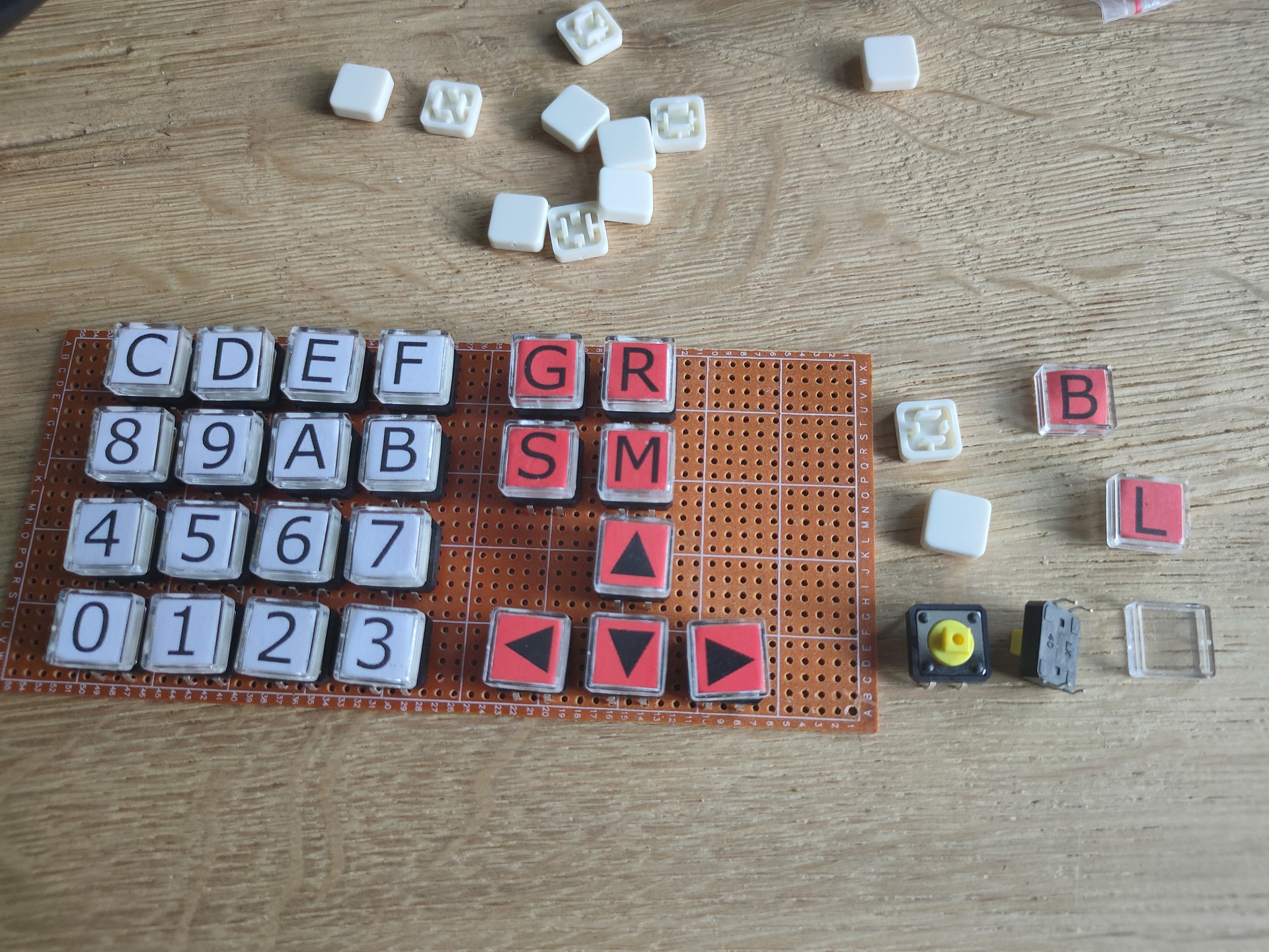
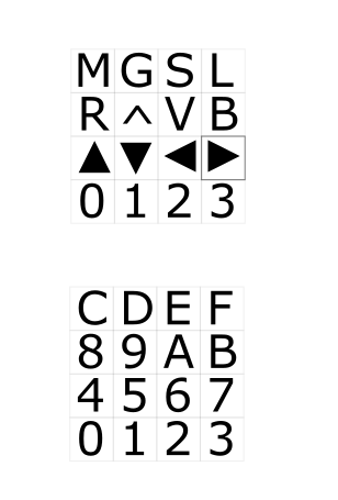
In this case designed for my 6502, but it is a generic setup.
I it just a dual 16key matrix decoder merged together. You can probably use this with raspberries, arduinos etc.
I wanted to use 74C923 but these are nowhere to be found. And even then, the number of keys wil be 20. So i am tying together two 74C922 using some logic in a PLD.
First draft
It wil be something like above. Using the data availabe signal i can combine both 16key matrixes. (In theory .. it is all untested)
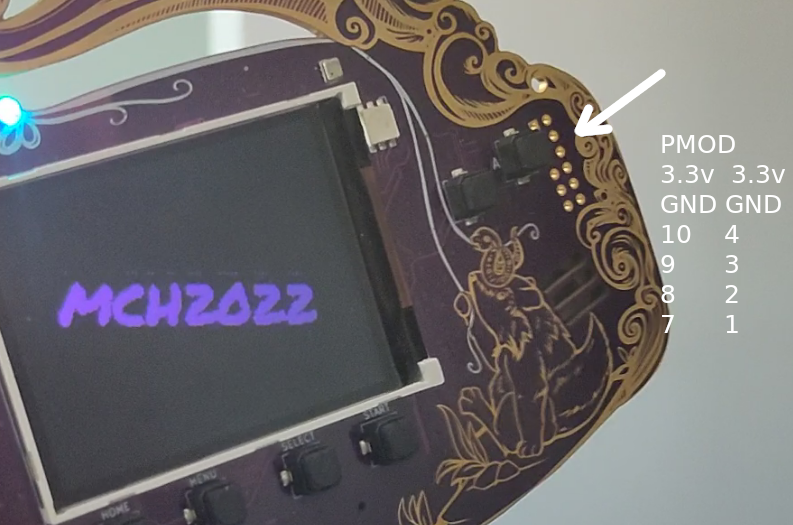
Almost … friday will be the day i’ll attend May Contain Hackers. Besides the awesome villages and talks.
UPDATE: 20220727 UPDATE: 20220812
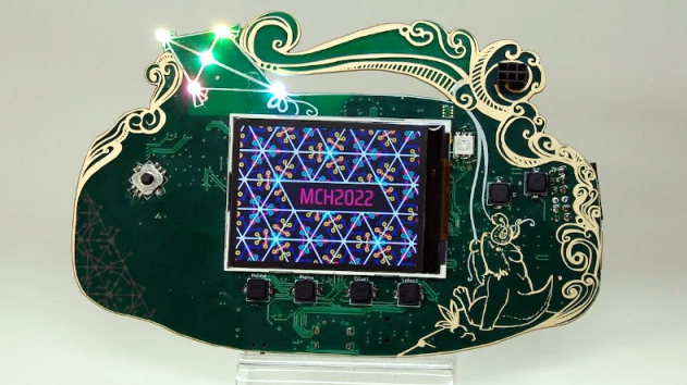
You get a hackable badge, this one is more amazing as previous versions.
I can’t wait to have a go at this cool gadget. I personally could do without the pcb fancy design.
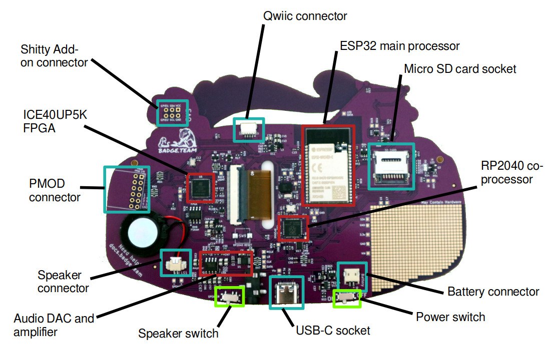
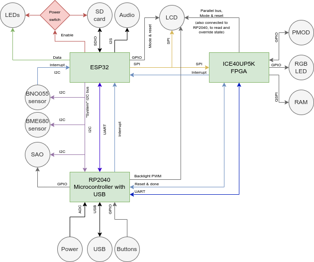
Espressif ESP32 Wrover-E with 16MB of flash storage and paired with 8MB of PSRAM, for front-end badge computing and compatibility with the badge.team ecosystem back to the 2017 SHA badge.
Lattice ICE40UP5K FPGA for hardware-accelerated graphics and user FPGA hardware designs.
Raspberry Pi RP2040 for advanced USB communication and board management.
2Ah LiPo battery to give you a full day of fun on a charge.
16-bit DAC with stereo output to headphone socket, onboard mono speaker.
ILI9341 2.2 inch TFT display with a 240 by 320 pixel resolution.
Bosch BNO055 orientation sensor.
Bosch BME680 environmental sensor.
The usual array of addressable LEDs.
SAO and Qwiic expansion connectors, FPGA PMOD expansion, plus onboard prototyping area.
Downloadable apps, micro python, Arduino ide programming. All kinds of GPIO pins, leds buttons, sound. Check out https://hatchery.badge.team/
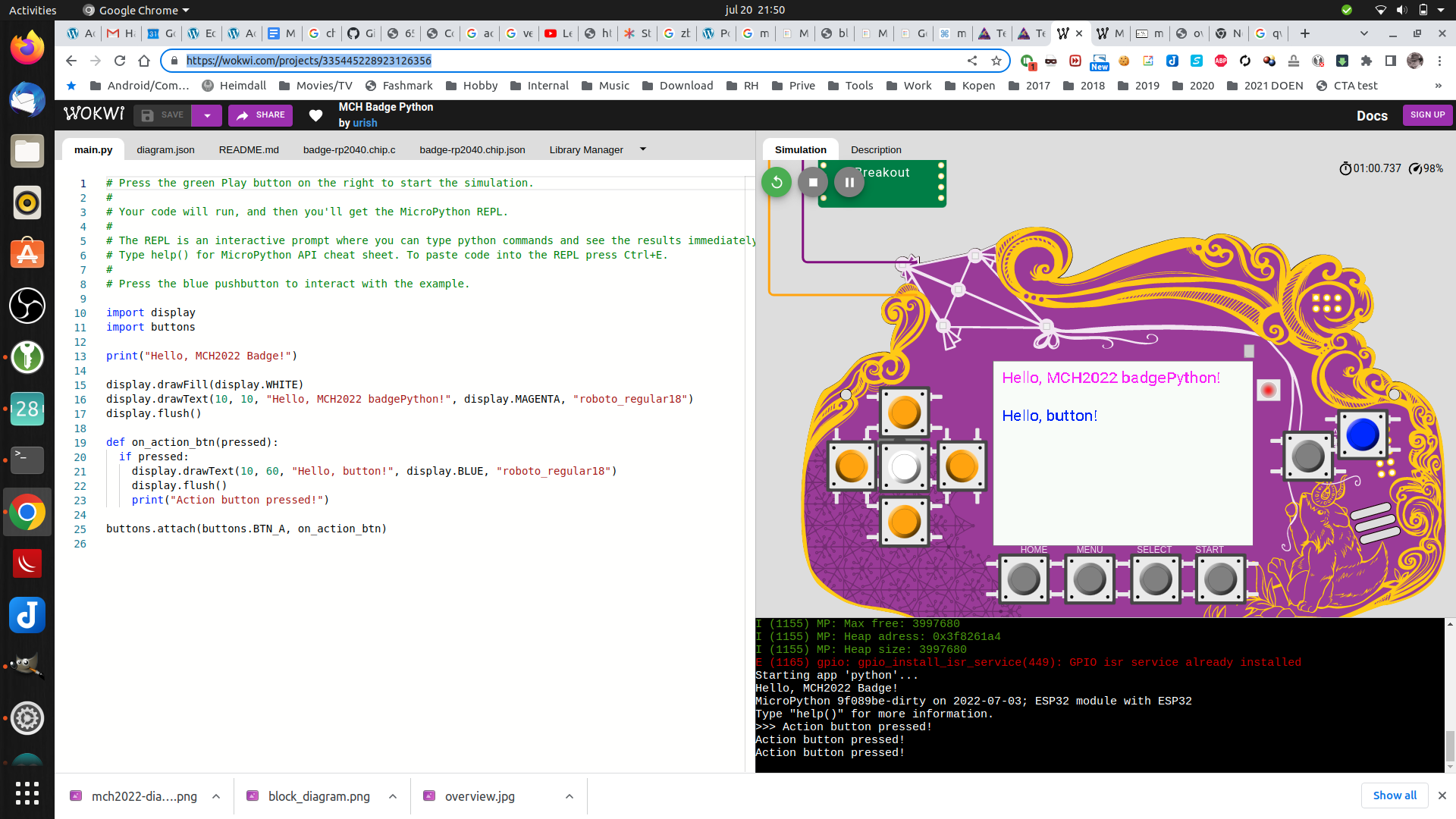
You can play with this virtually here! https://wokwi.com/projects/335445228923126356
So much potential! Great start for a DIY project.
I won’t post about the workings, thats all well documented online. I shall post about the hacks/findings i personally did.
UPDATE: 20220727 Made a micropython program to keep your NameTag level to the ground (Better version)
UPDATE: 20220812
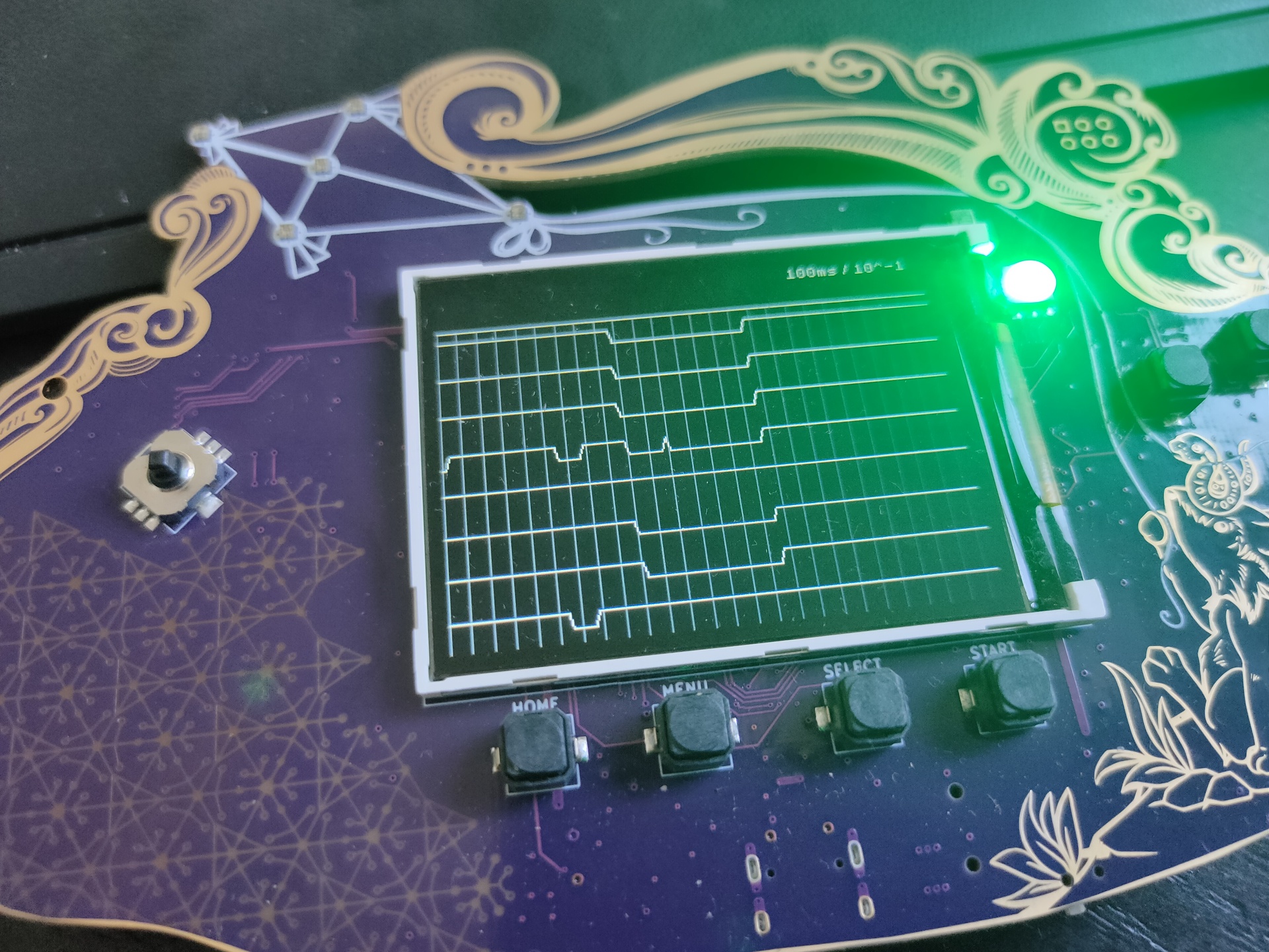
Someone made a 8bit logic analyser using the pmod connector !
Next week i’ll be going to May Contain Hackers 2022, what to bring? My old friend Bigred will be there, many others couldn’t make it …
What to bring and do:
Laptops
Arduino touch project?
My new 6502 breadboard computer?
The DVB-T / DAB / FM stick
Besides the emulators on my laptop, maybe i’ll bring this little thing (Or a real C64?)
Booting in 4 seconds! Running Vice in 50 or 60 Hz Low latency video! Can emulate cartrides, floppy’s When you connect joysticks or a real C64 keyboard to the GPIO pins it will use that. SID sound using ReSid CRT emulation (look for BMC64 or combian)
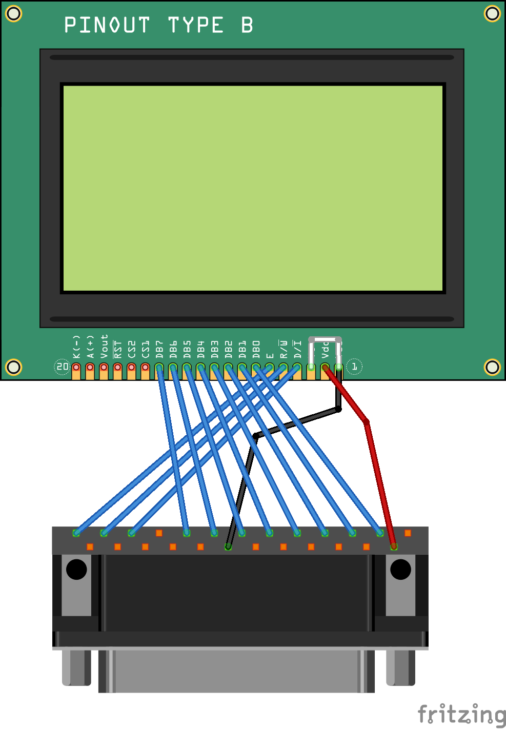
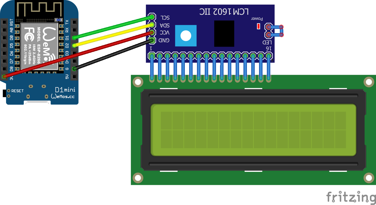
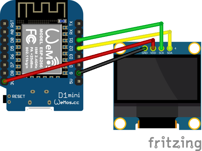
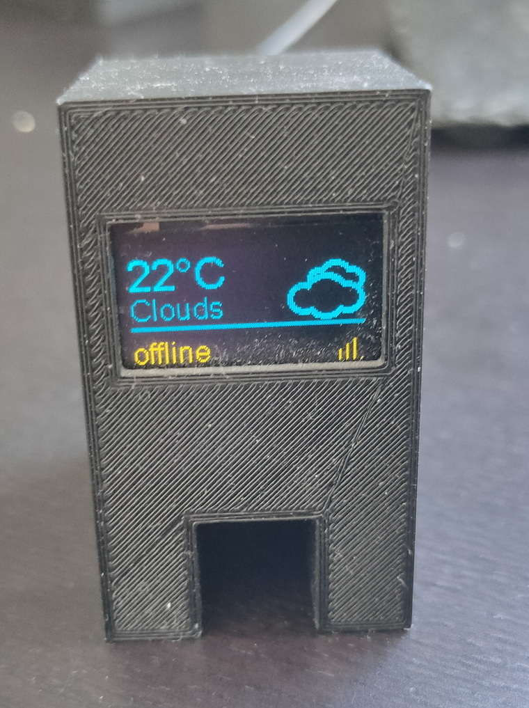
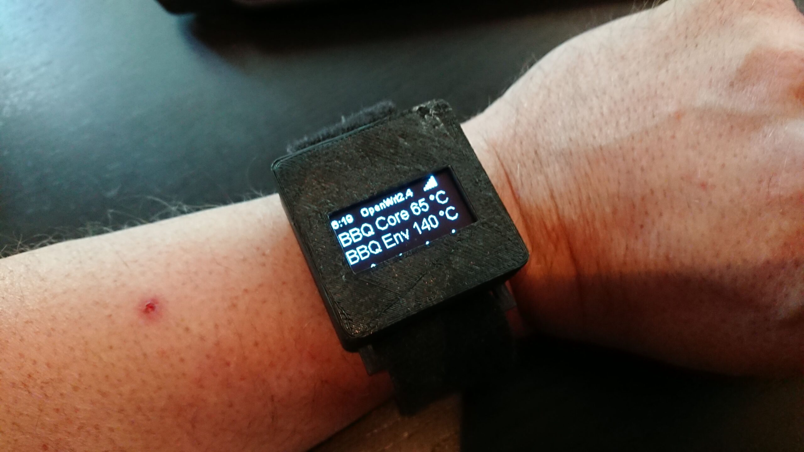
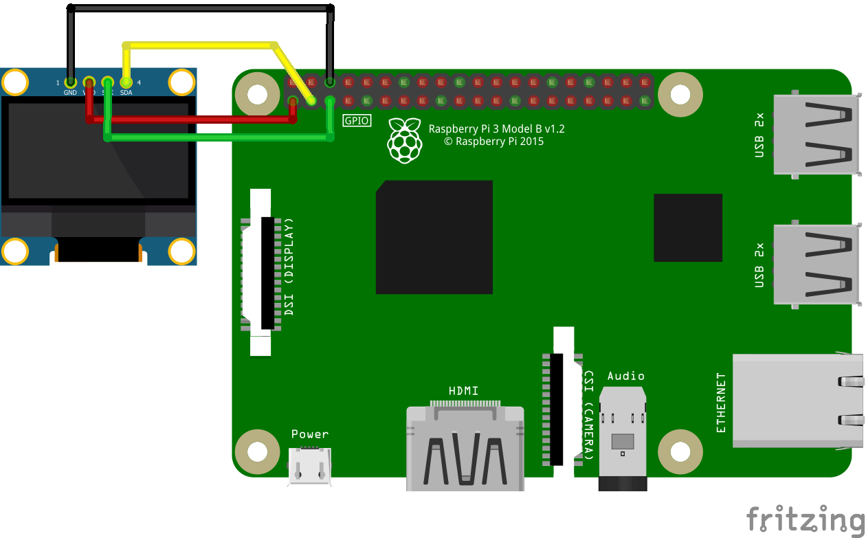
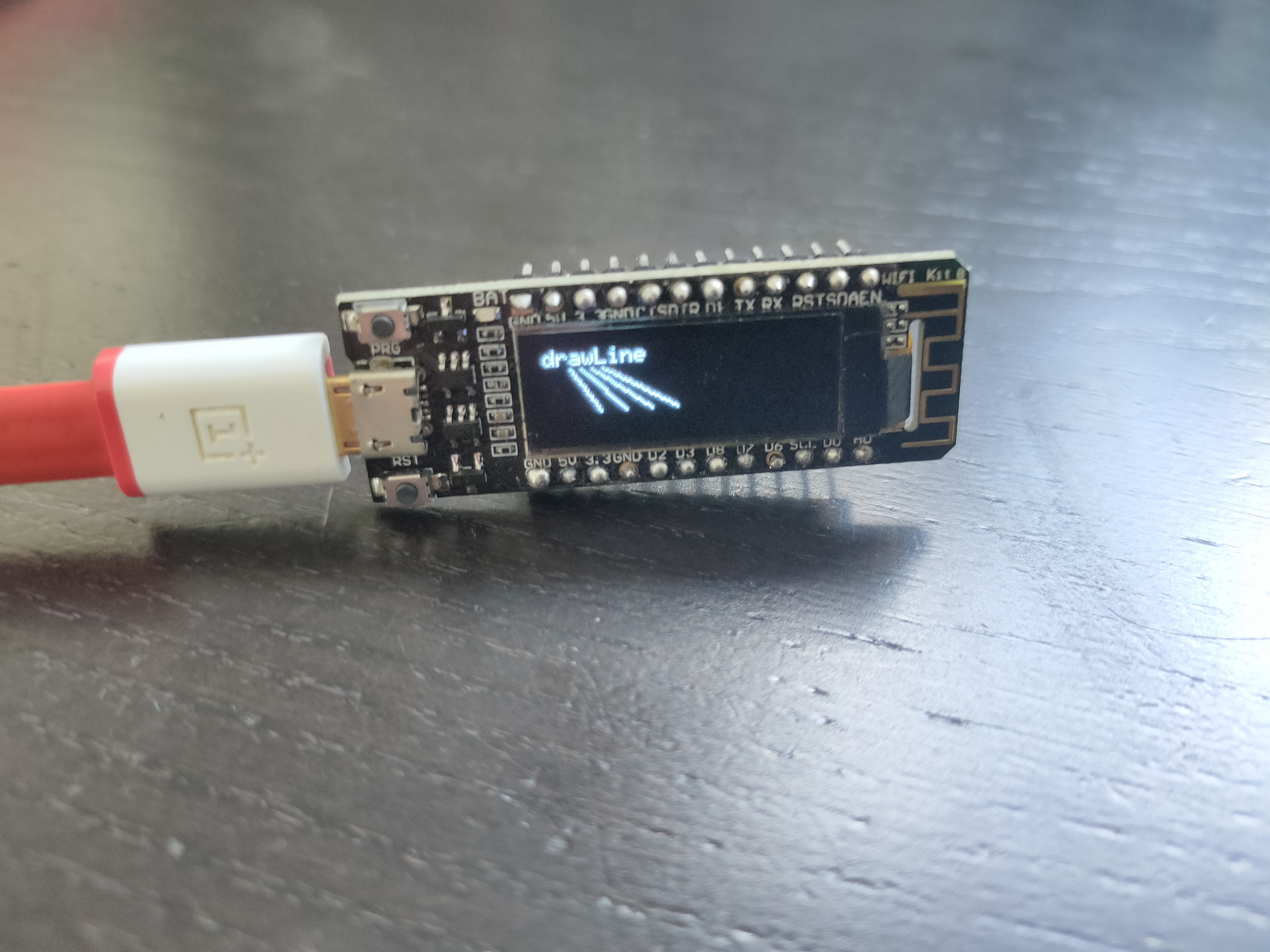
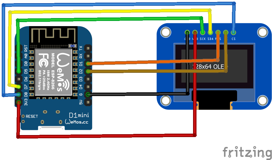
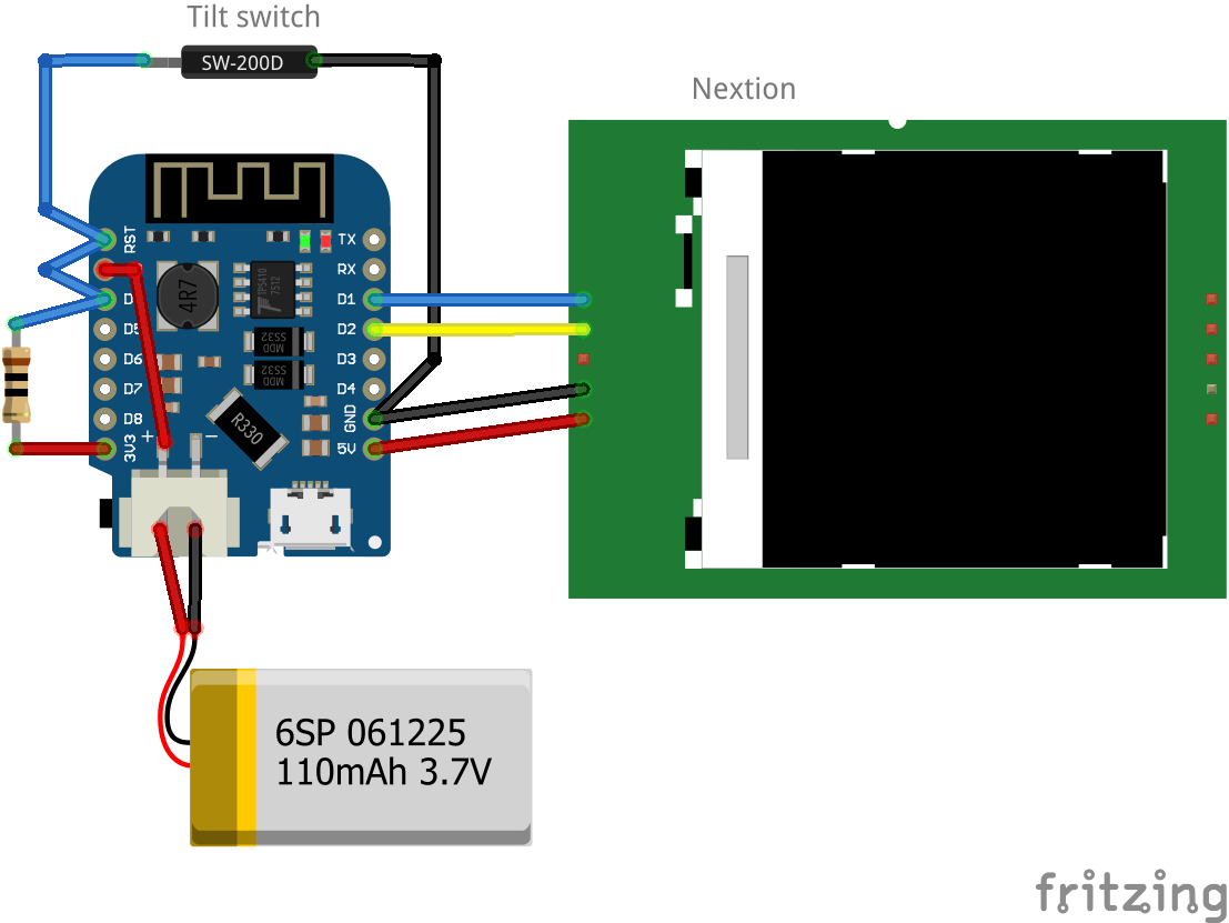
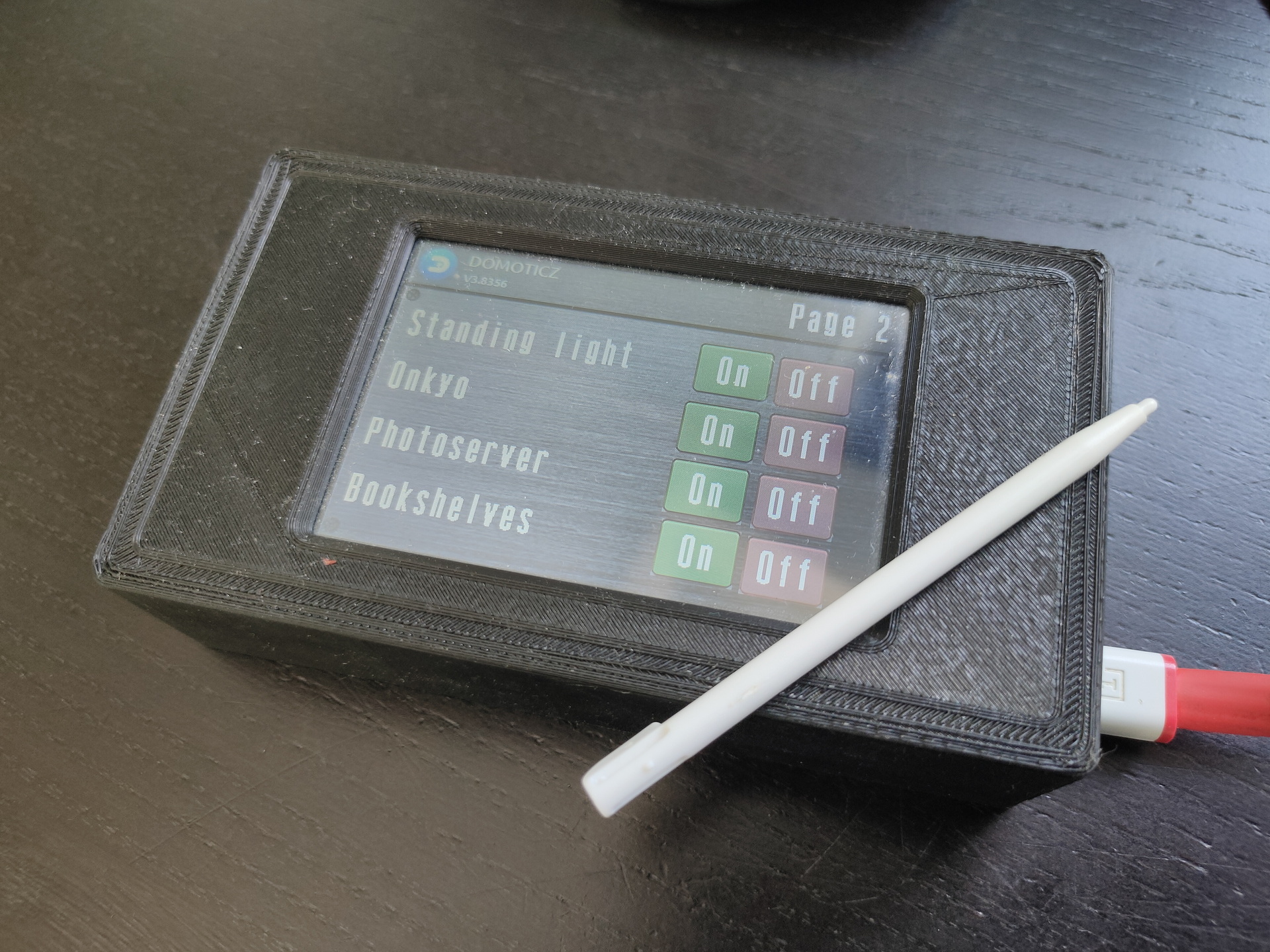
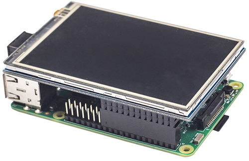
Below some examples and connection diagrams to control displays. More code and complete schematics will be added on this page or on a separate projects page.
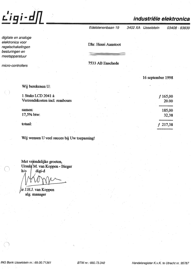
UPDATE 20230119 Cost of 20×4 display in 1998
LCD
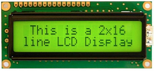
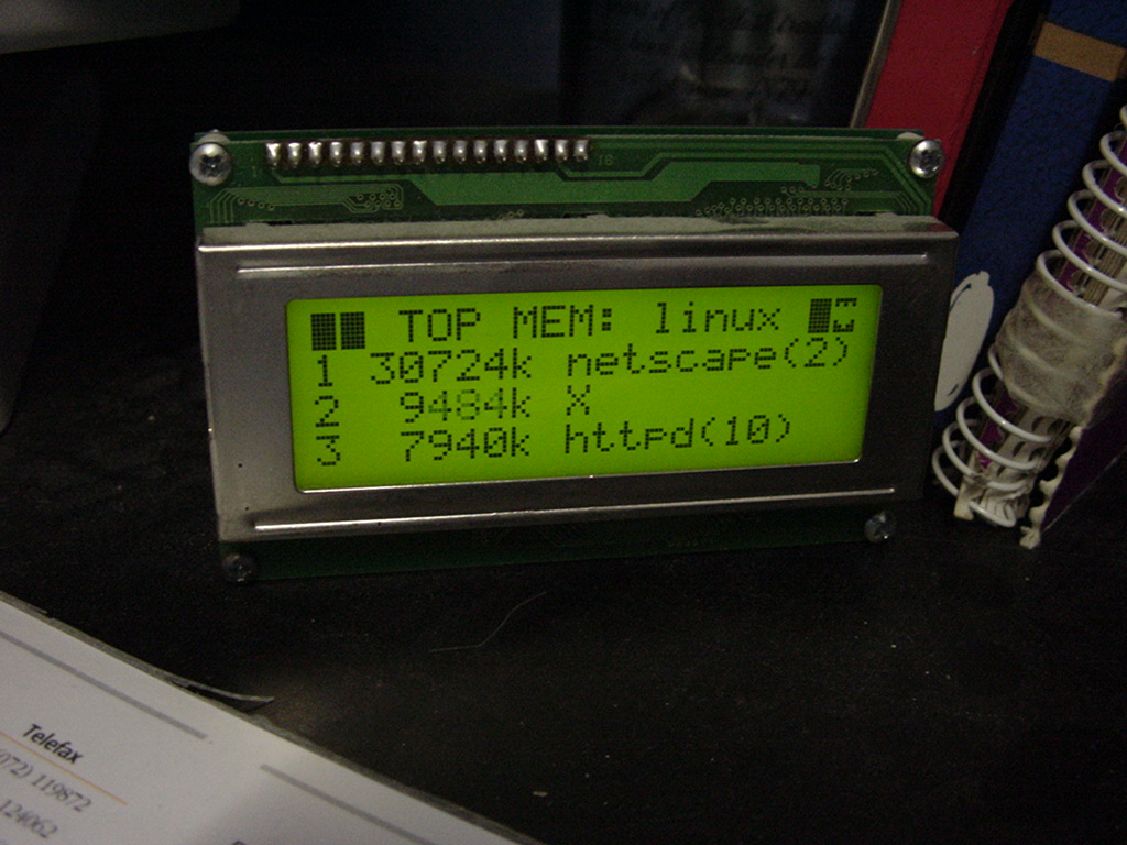
I’ve used a LCD display like this (HITACHI HD44780) on my PC in the 90s, and also written code to use this as a monitoring device on my amiga.
On Linux i used LcdProc – This module also was equiped with a serial connector
Now (2023) it is 8 euros! When bought now fl to euro 98 Euro or 107 $
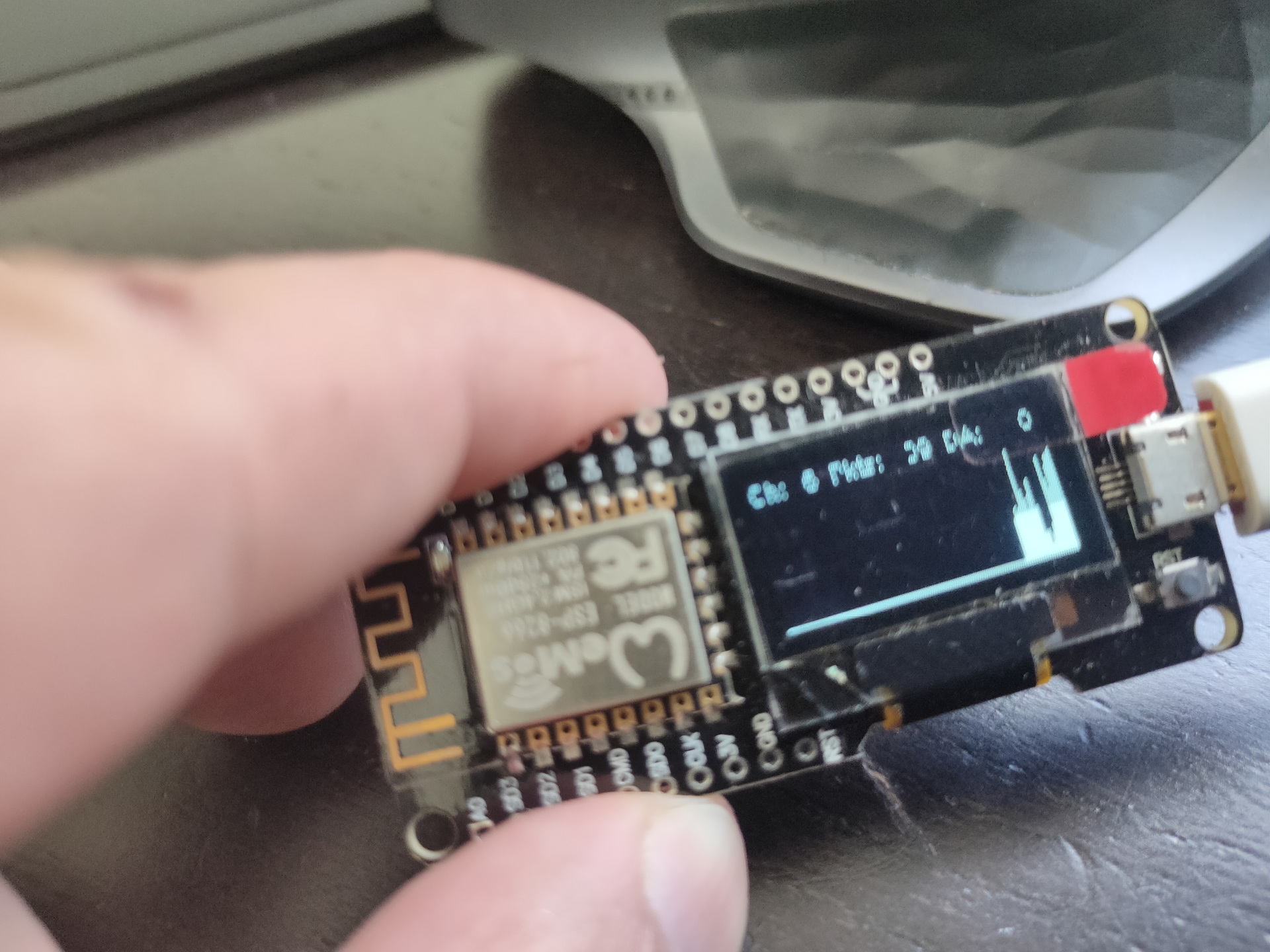
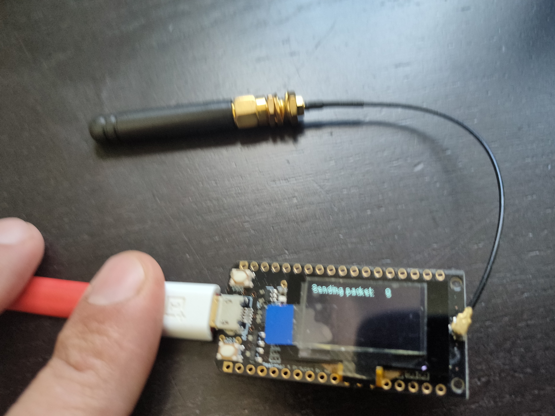
Some arduino’s have embedded displays like those i’ve used for a Lora project.
No usedWifi packet monitorLora test
Other means of connecting : SPI
SPI connected display
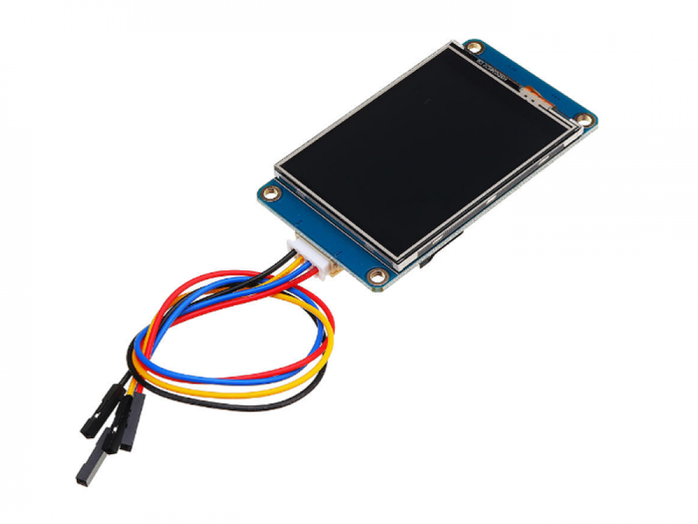
Nextion
Nextion is a Human Machine Interface (HMI) solution combining an onboard processor and memory touch display with Nextion Editor software for HMI GUI project development.
Using the Nextion Editor software, you can quickly develop the HMI GUI by drag-and-drop components (graphics, text, button, slider, etc.) and ASCII text-based instructions for coding how components interact on the display side.
Nextion HMI display connects to peripheral MCU via TTL Serial (5V, TX, RX, GND) to provide event notifications that peripheral MCU can act on, the peripheral MCU can easily update progress, and status back to Nextion display utilizing simple ASCII text-based instructions.
edit cmdline.txt
add "fbcon=map:10 fbcon=font:ProFont6x11 logo.nologo"
at the end
edit config.txt
add between custom comments at the bottom
dtoverlay=piscreen,speed=24000000,rotate=90
# Or check http://www.lcdwiki.com/3.5inch_RPi_Display
Above display’s i’ve used for Picore Players and the Lidar POC
To try: Getting above display running with a arduino https://github.com/PaulStoffregen/XPT2046_Touchscreen
Raspberry HDMI display
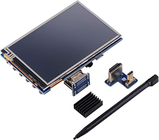
Easiest of them all, just connect with HDMI, there is a adaptor for hdmi-hdmi (versions 1,2,3) and hdmi-mini-hdmi for RPi4 variants.
Epaper and 7-Segment displays
Other means of displaying information are for example
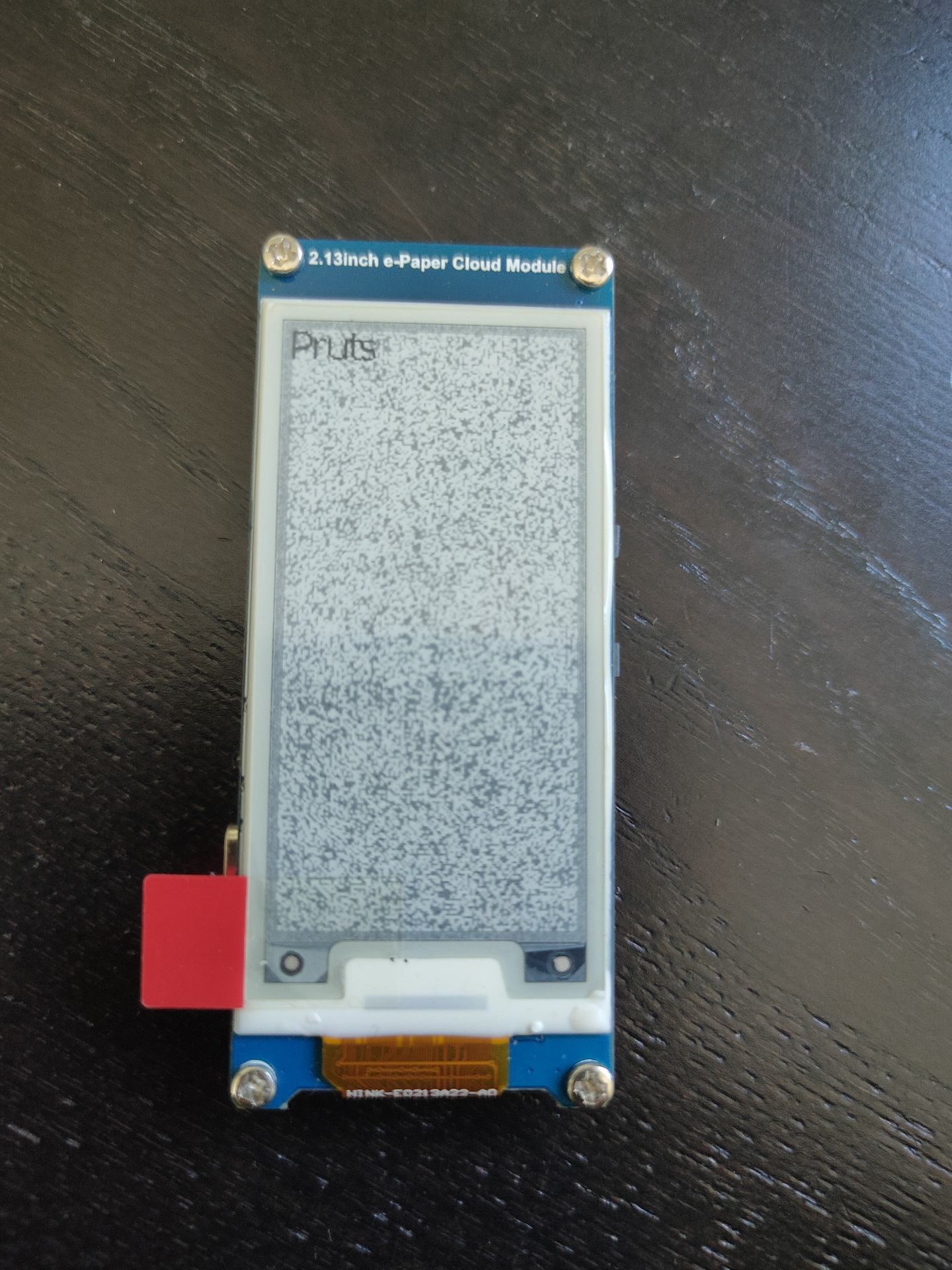
Epaper
ESP with epaper module, disconnected power for a while, artifacts appear.
7 Segment displays
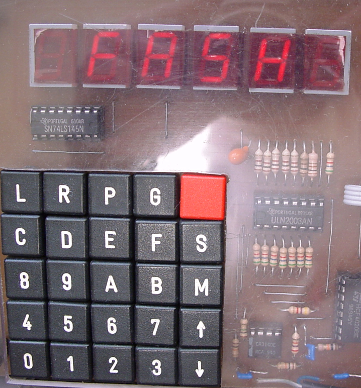
I used a lot of 7-Segment display’s in the past. They look cool and are hardcore.
My homebrew computer uses this
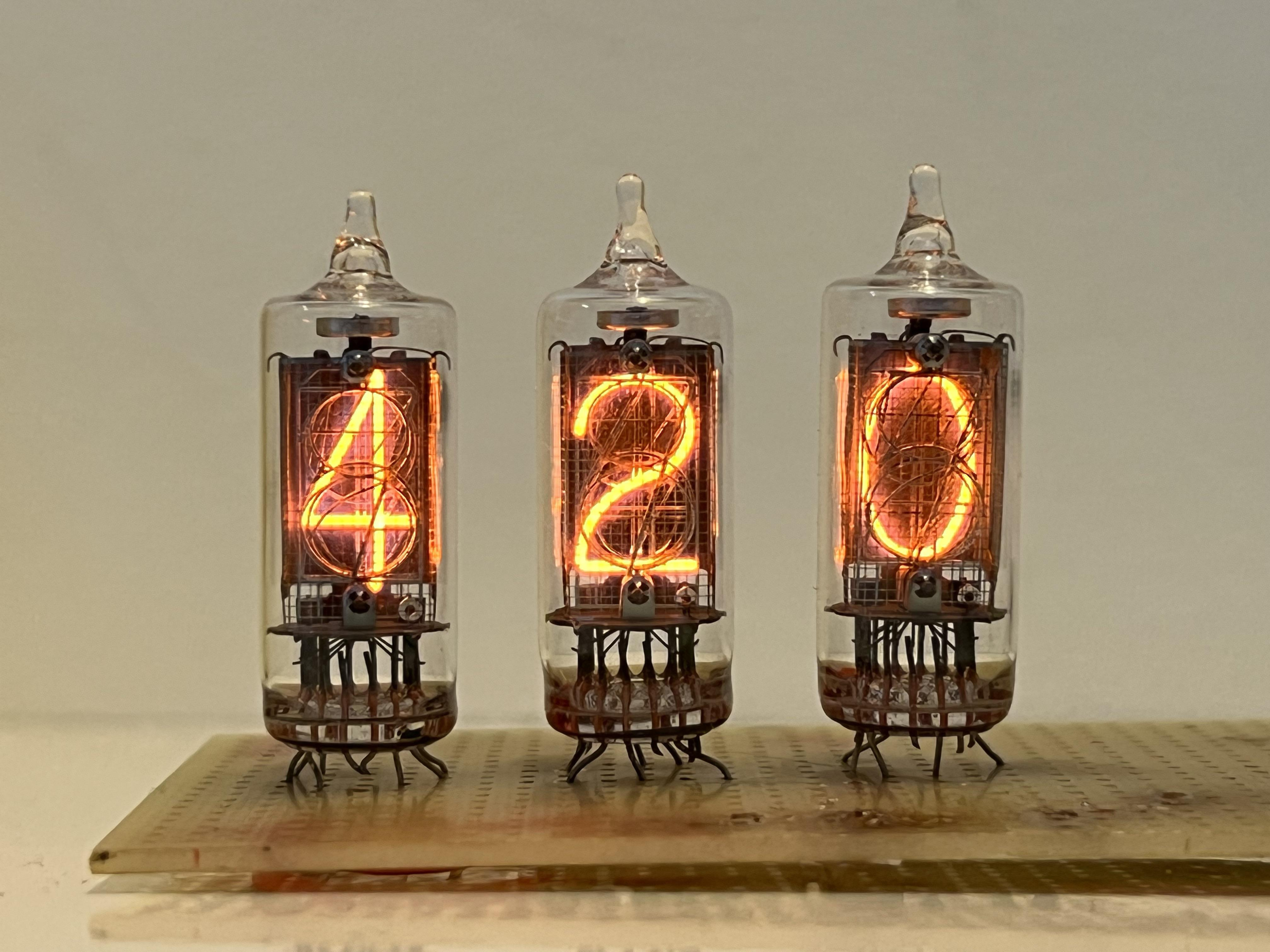
Nixie tubes!
And there are https://en.wikipedia.org/wiki/Nixie_tube .. I’ve never had those
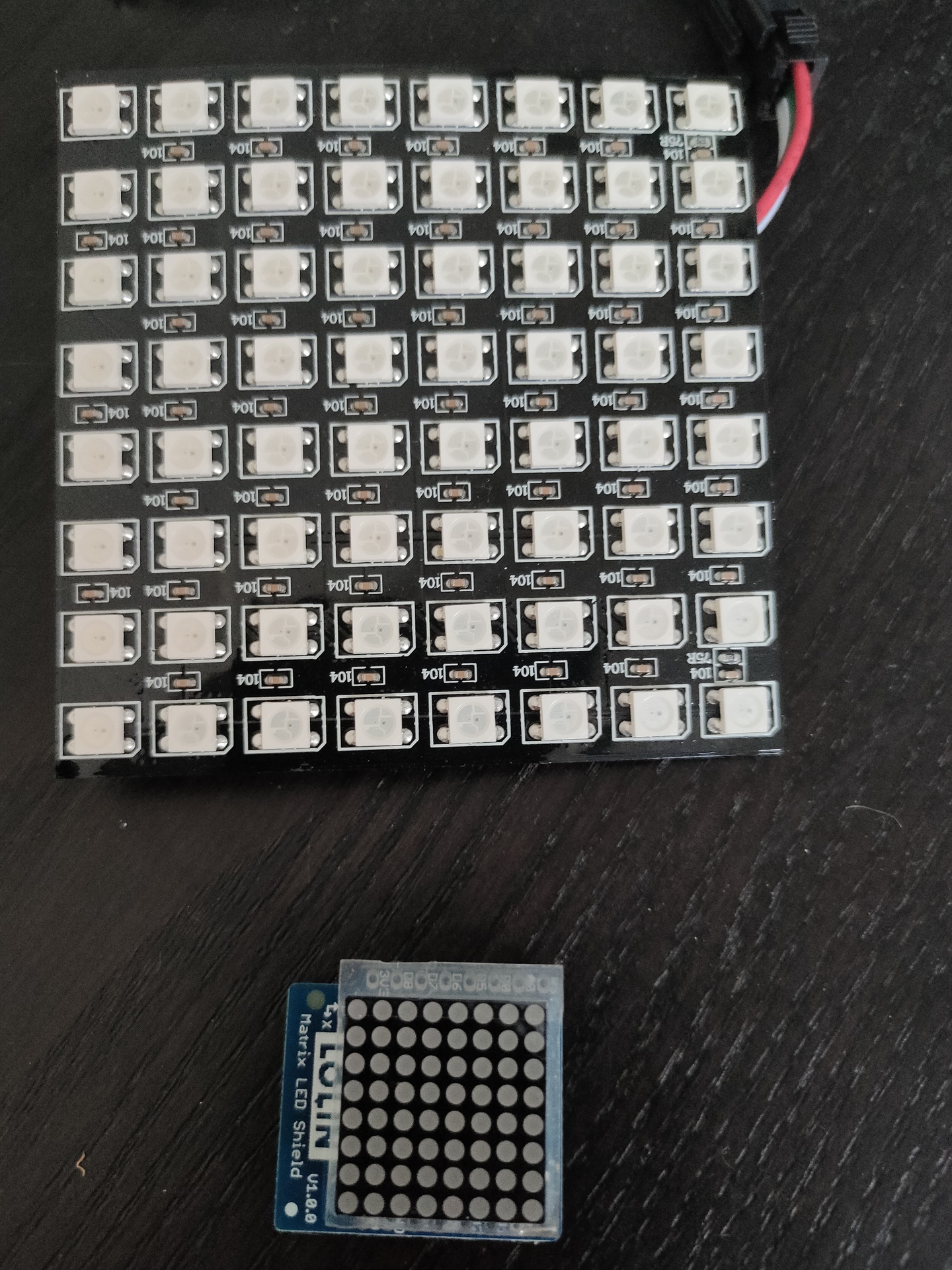
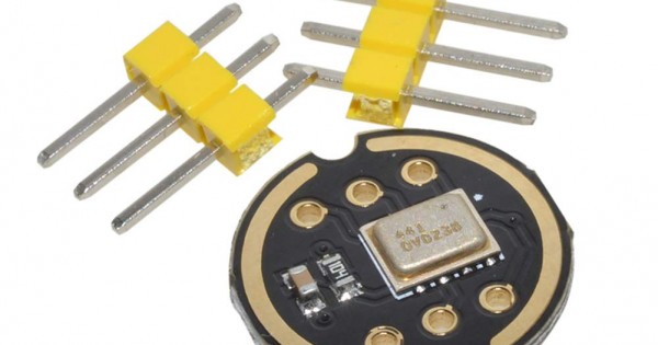
Above bigger 2D display i used with Wled and a digital microphone, so its sound reactive. The lower part i got in recently .
While you can use screencapture to record virtual machines, to real machines it is a different story.
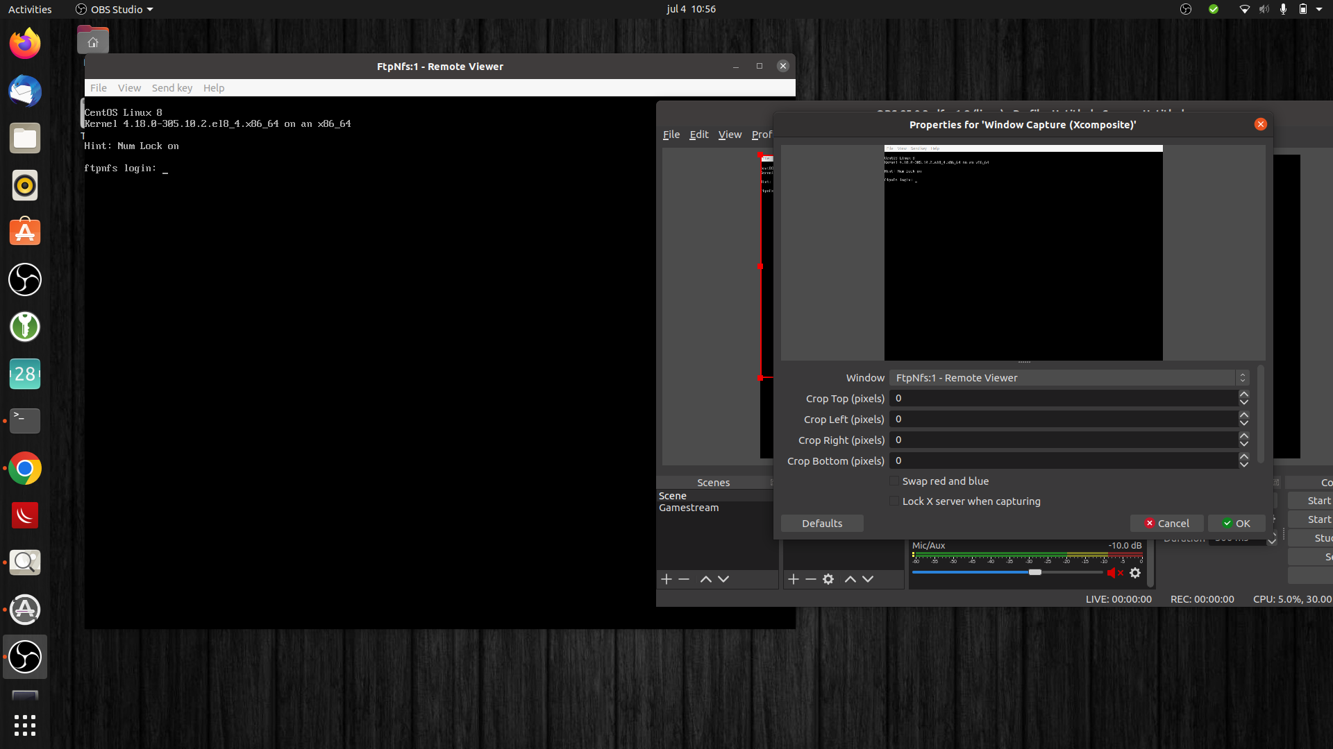
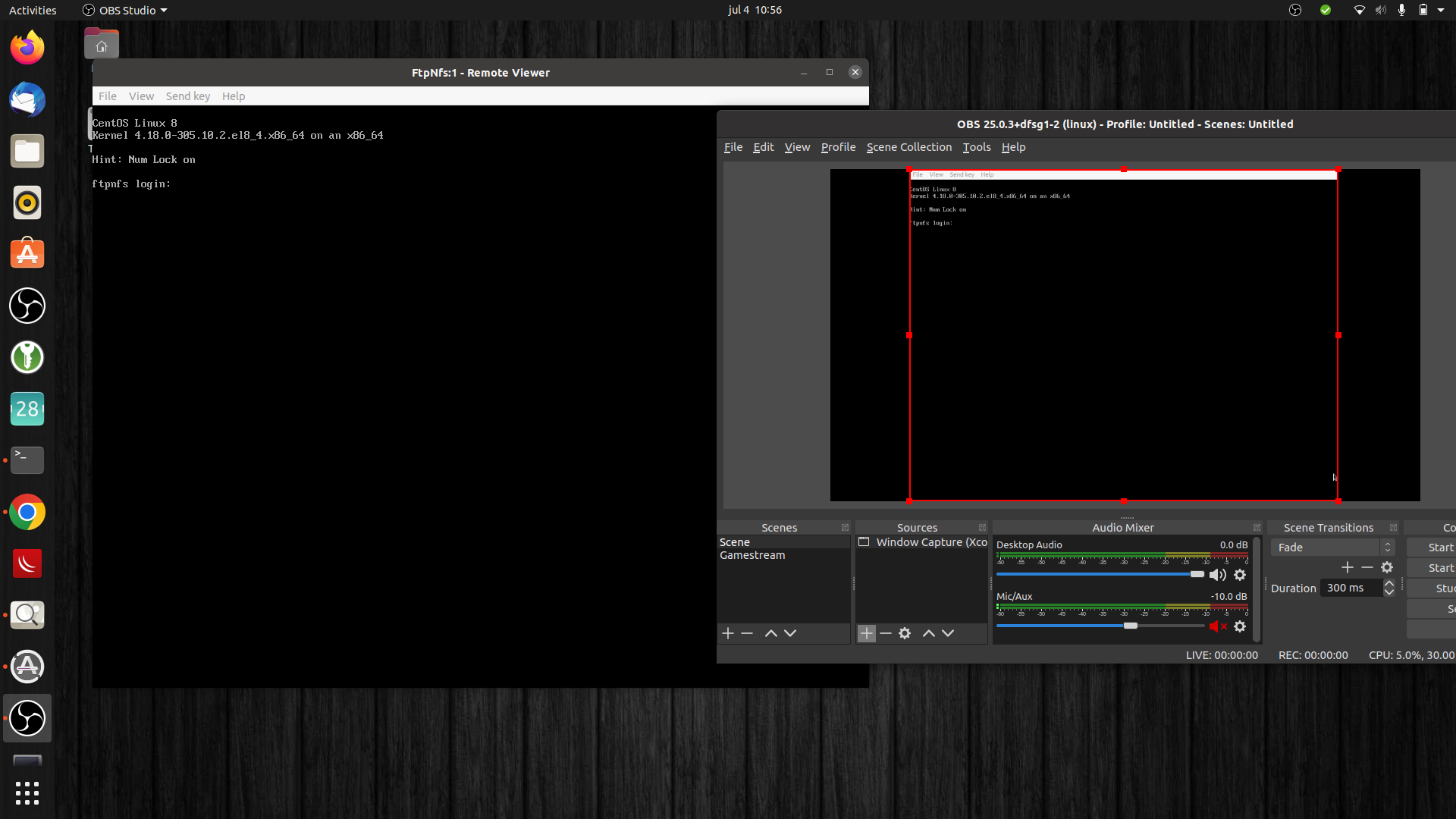
Virtual machines running locally or remote can be accessed with spice/vnc or rdesktop. So you have a window displaying the remote screen, which you can capture using window capture.
There are also emulators which you can window-capture. But i want the real thing when available. Emulators give a too crisp screen output. And you want to have the real SID chip sound.
Hardware capturing:
Recording Virtual machines
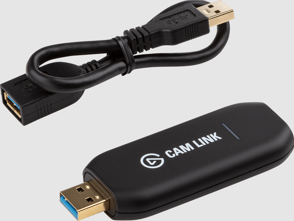
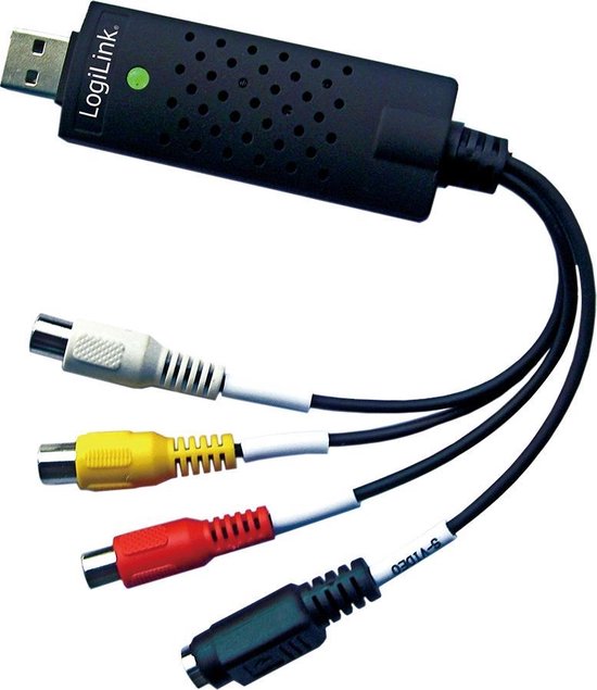
I’ve got two capturing usb sticks:
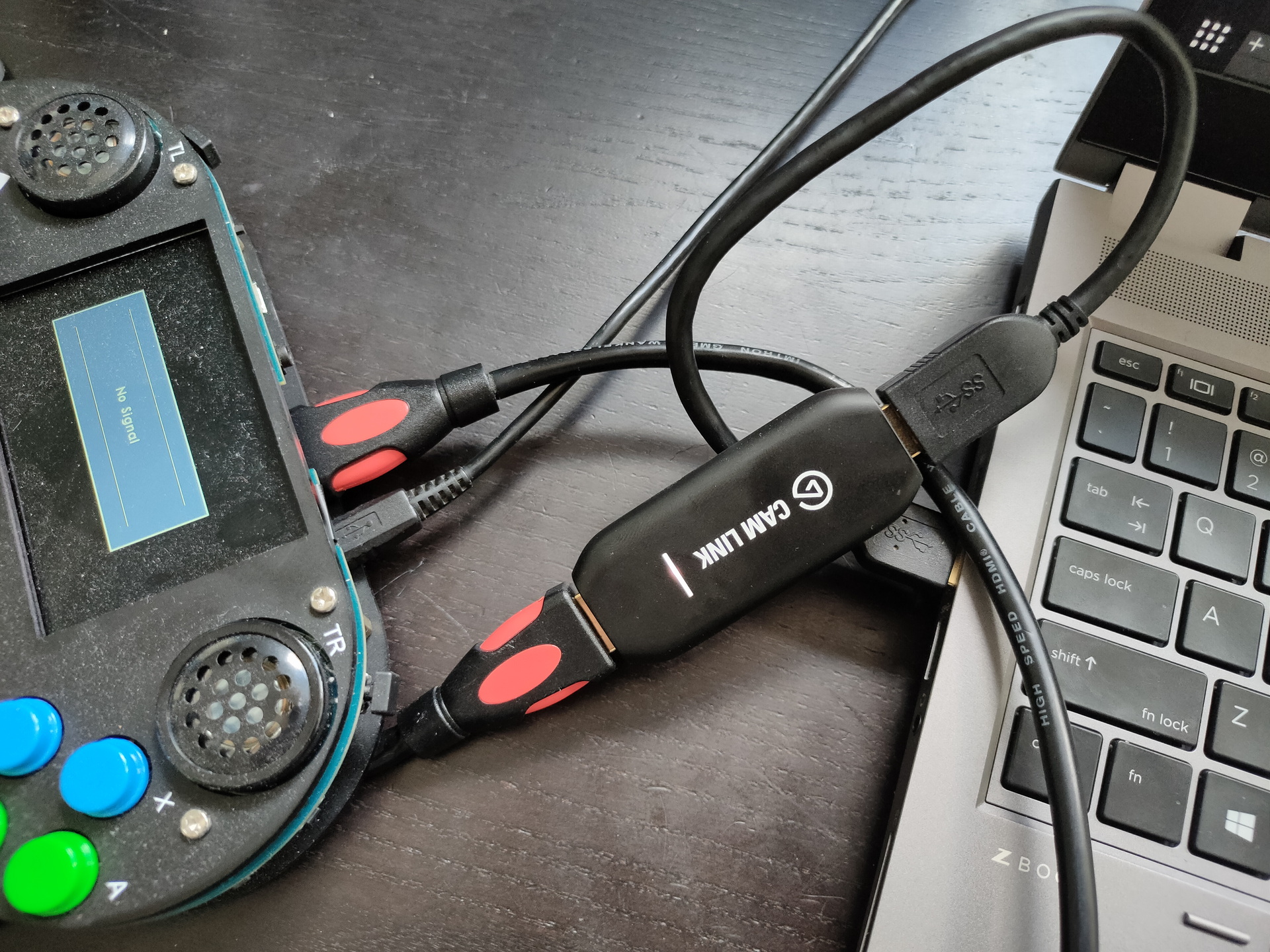
Camlink 4K for hdmi capturing (Which i use mainly for my nikon)
Basetech BR116 RCA and S-Video capture (NTSC 720 x 480 , 30 FPS/PAL 720 x 576 , 25 FPS)
Devices and recording:
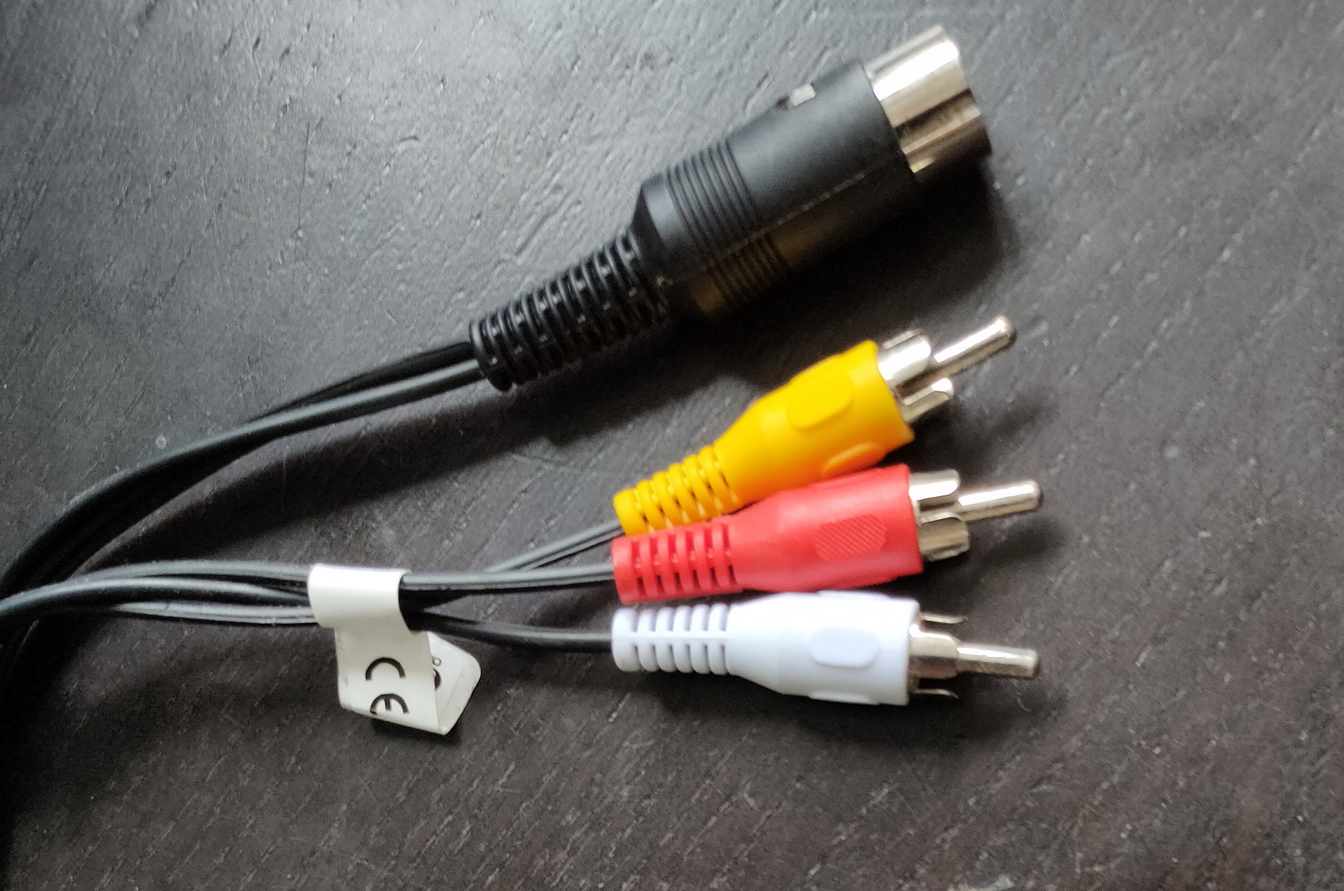
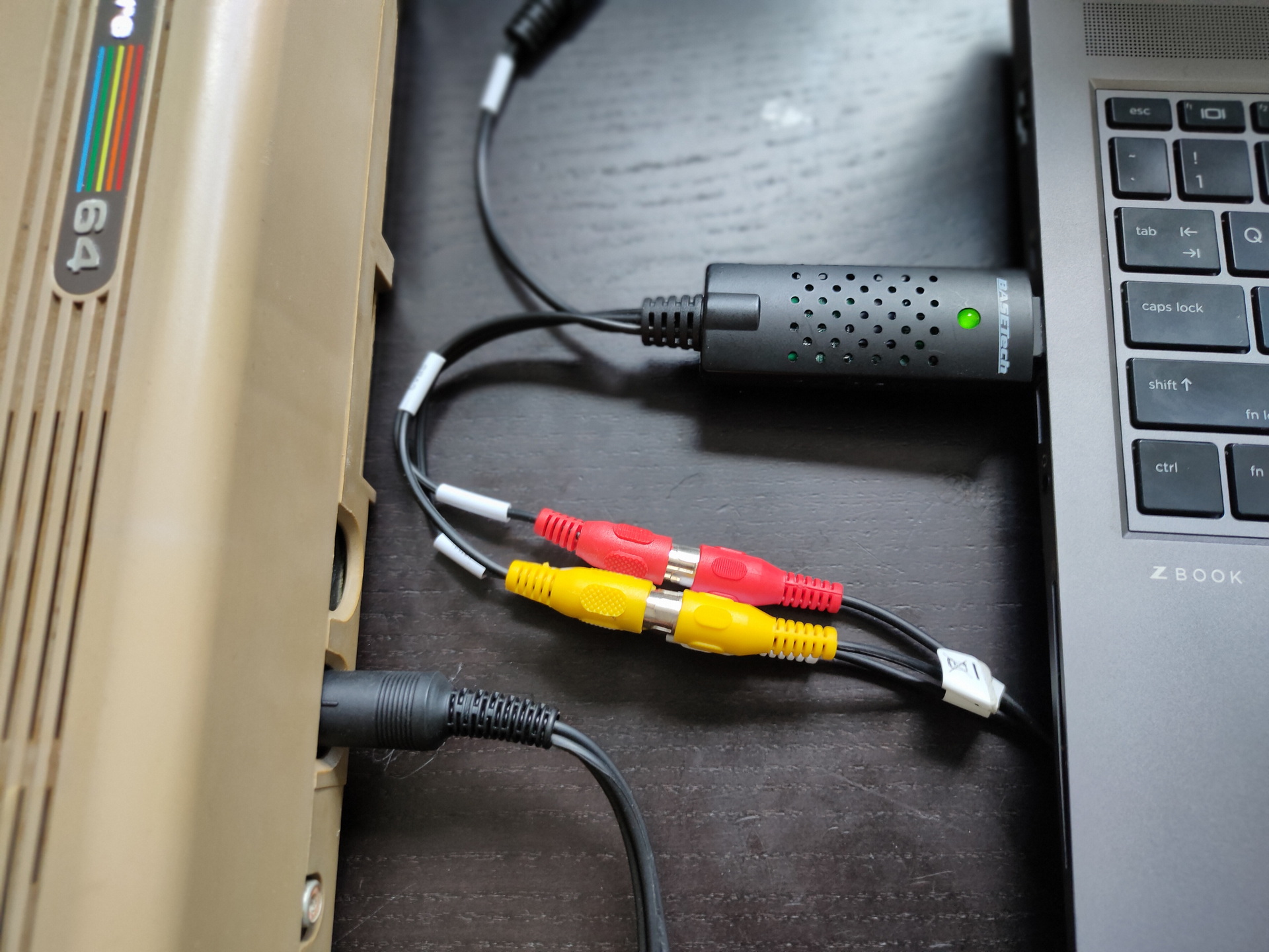
C64 – Use Basetech, and the DIN to RCA cable
Vic-20 – same as above
Raspberry – Use a HDMI and Camlink
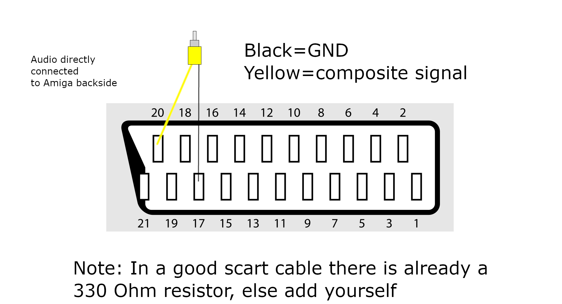
Amiga – I use the basetech and grab the composite signal from the Scart connector, another solution is to use a A520 Modulator, which has Composite out. (There are schematics on the internet to connect hdmi to your amiga)
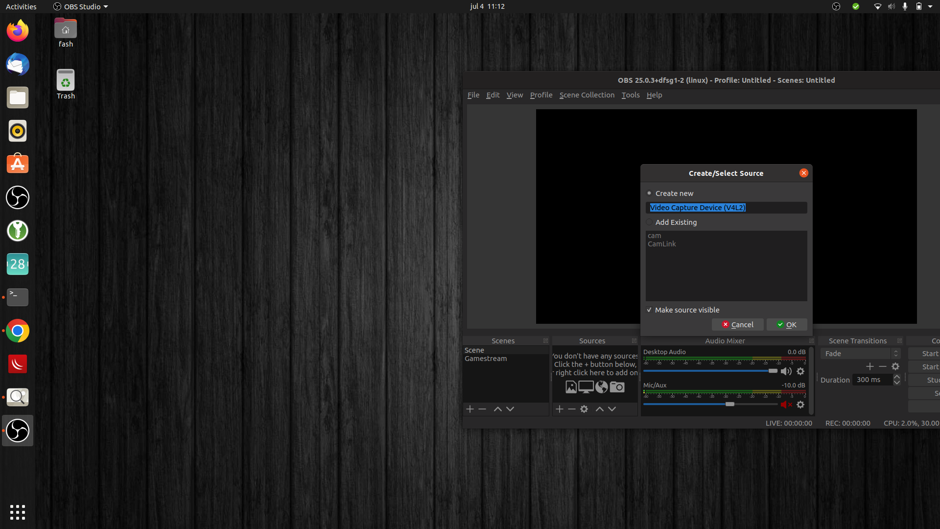
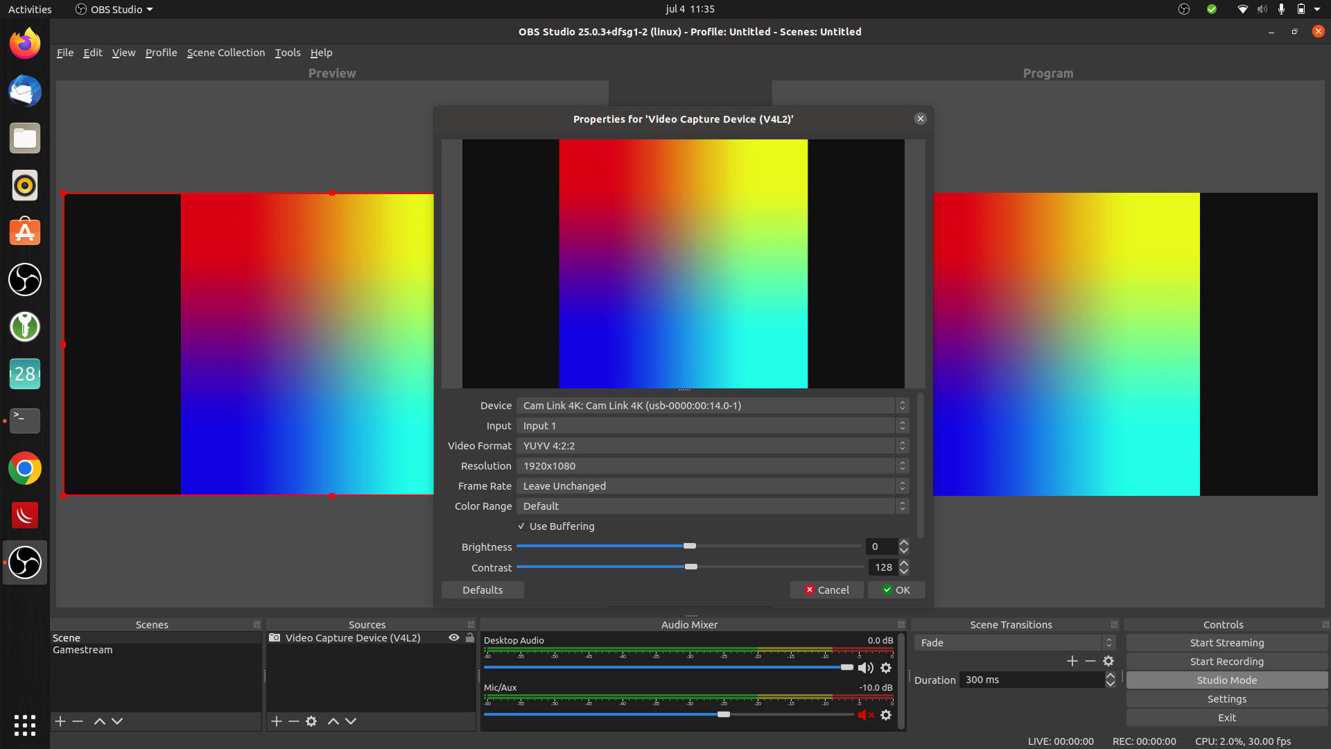
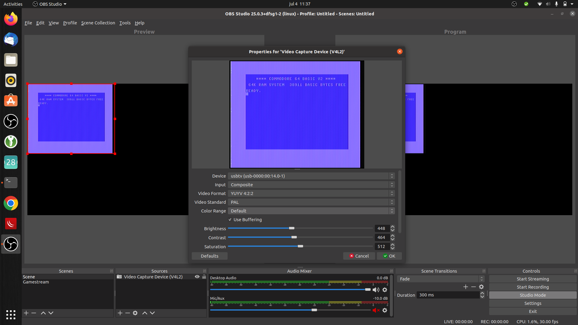
C64 DIN RCA cableC64 connectedAdd video capture deviceRaspberry HDMIRaspberry bootingC64 settings
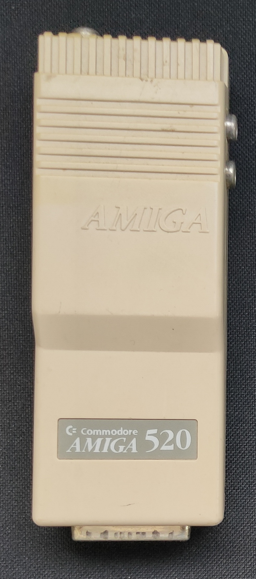
Amiga A520 Modulator
The 520 Modulator connects to the amiga using a DB23 connector, and a Y cable for the 2 rca audio jacks. It outputs a composite video signal, and RF modulated signal to connect to a old Tube/Crt monitor
How i connected my amigaSubD23 to Scart plus audio
When recording video from those screens, i configure my OBS file format to MP4. This makes it easier to embed into websites. Only downside on writing to MP4 instead of mkv is the fact that the file probably isn’t recoverable when something crashes.
Audio capturing :
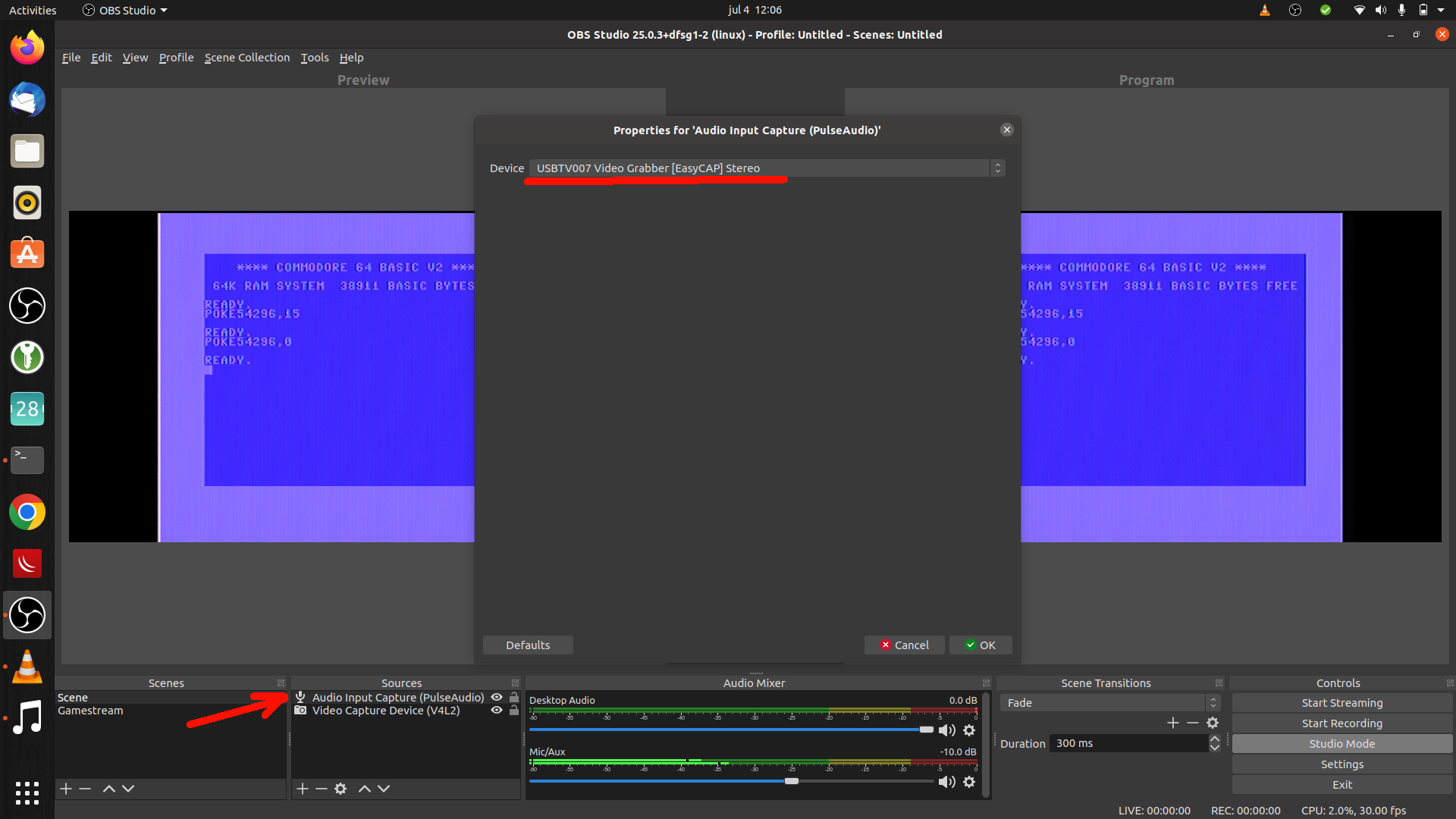
When capturing your movie don’t forget to add a audio source to your OBS sources. Use Audio input capture, or you can use Audio output capture when sound is playing by your system.
Demo a friend made using a demomaker (Music starts half way)
Flightsim on a Amiga (See more on flightsims)C64 Hellraiser (part 1) no de-comb/de-interlace filter
Note: check your output/cables https://www.youtube.com/watch?v=entQosOLjEI
In the past i’ve used a home build Logitech Squeezebox server (as it was called then), Picore player and tried volumio. Picore player has been sitting in my livingroom for ages, but was converted to a Node-Red Dashboard and recently Home Assistant Dashboard. (Has been a dasticz daskboard also)
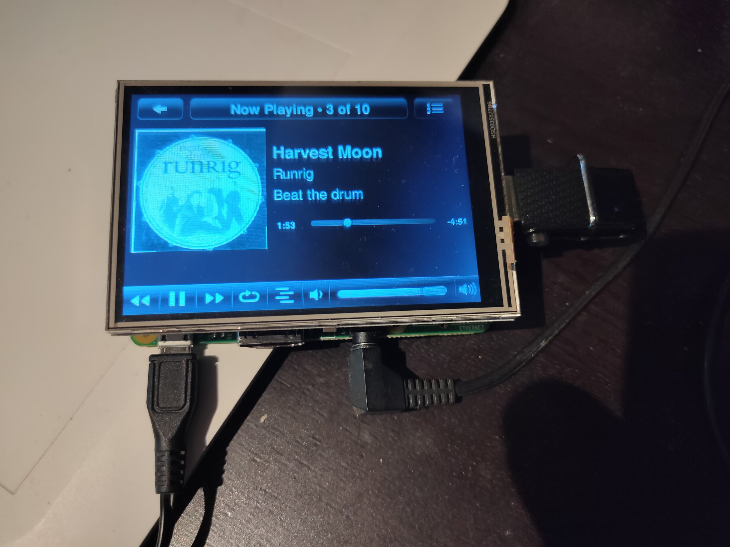
Today i build another version, smaller and with a screen. Why? .. because of being ‘offline’ or ‘offgrid’ on our holidays. The car we are driving only has a Aux input.
Most of the installation is as mentioned on: https://docs.picoreplayer.org/projects/add-a-display/
I edited /opt/bootsync.sh to get /dev/sda1 mounted persistent use pcp br after editing.
Default user/pass : tc piCore
Controlling the thing is via touch or a app on my phone using wifi hotspot.
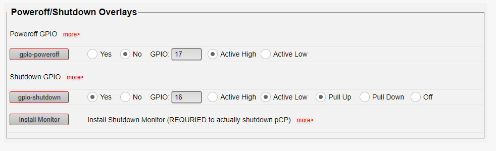
Shutting down piCore is done by cutting the power, due to everything being mounted readonly. EXEPT When you are using LMS server installation, which uses a database. But there is a tweak for a shutdown button.
I’m using GPIO 16 because i’ve got a screen connected. Active LOW, means you have to connect a pushbutton/switch between GND and GPIO pin. (nearest Vcc OR Gnd)
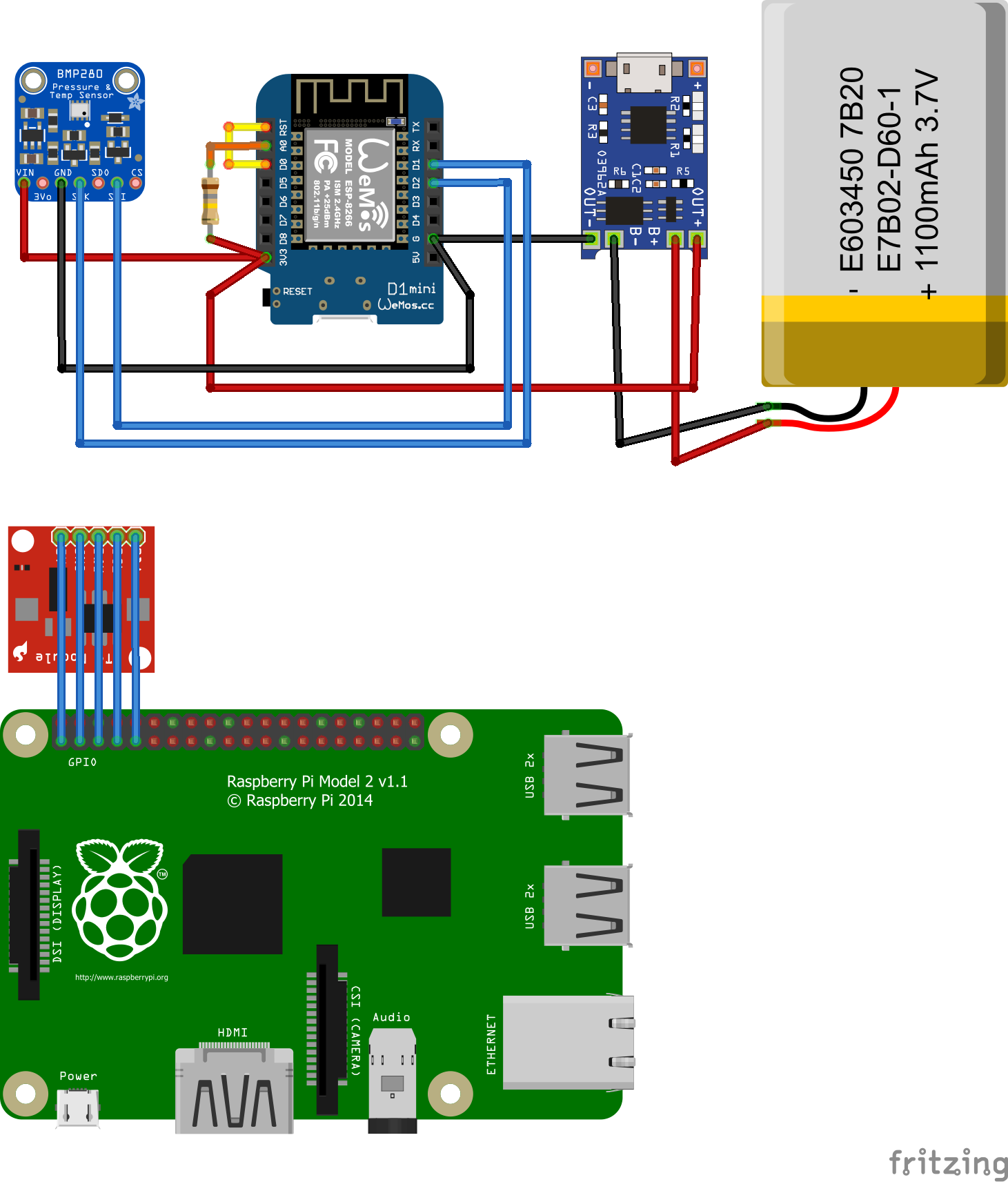
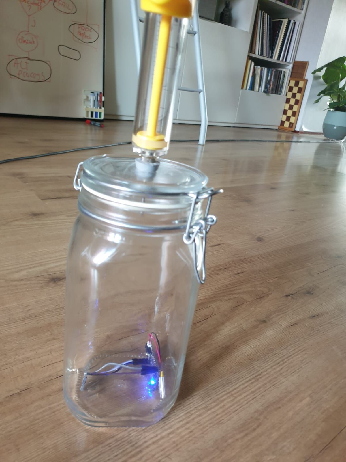
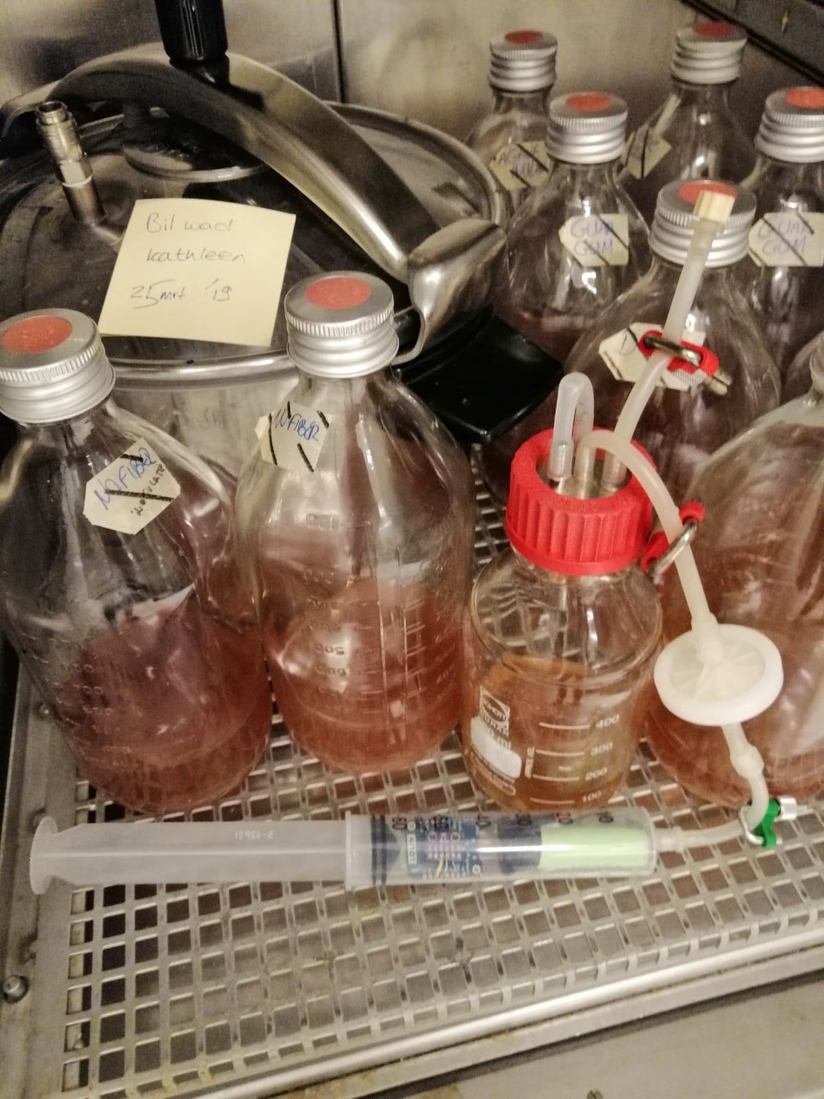
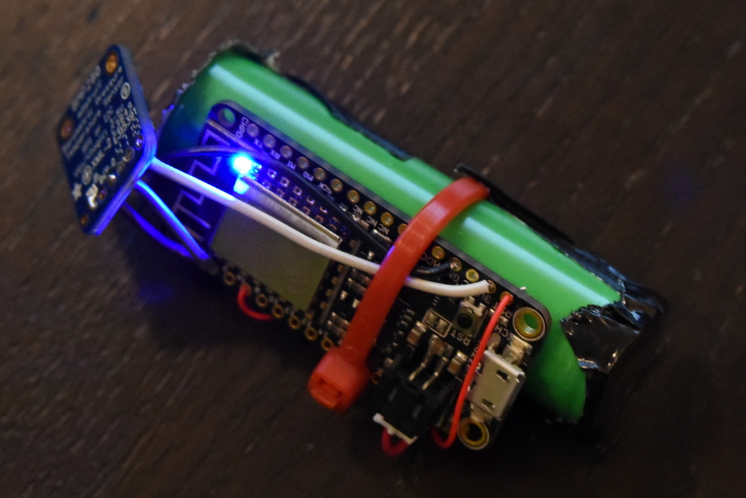
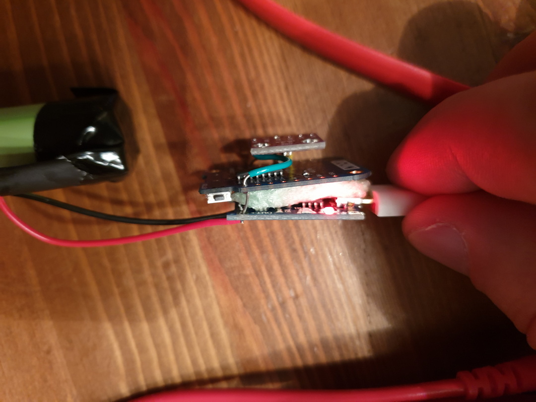
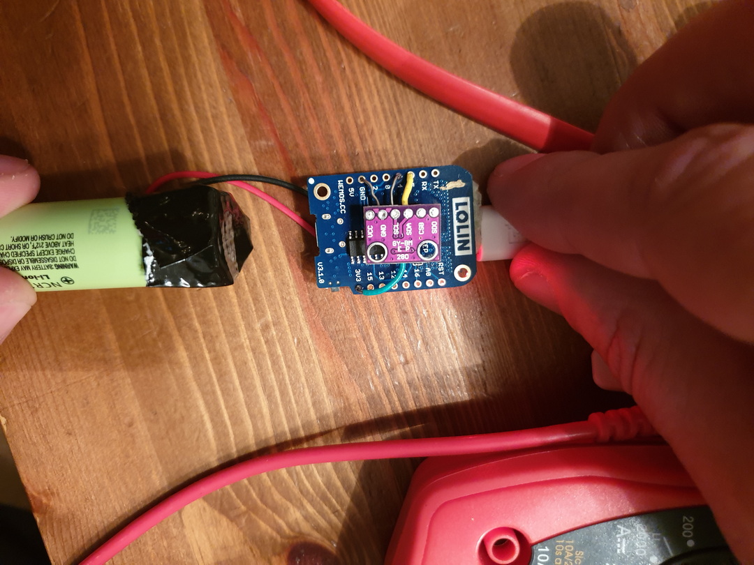
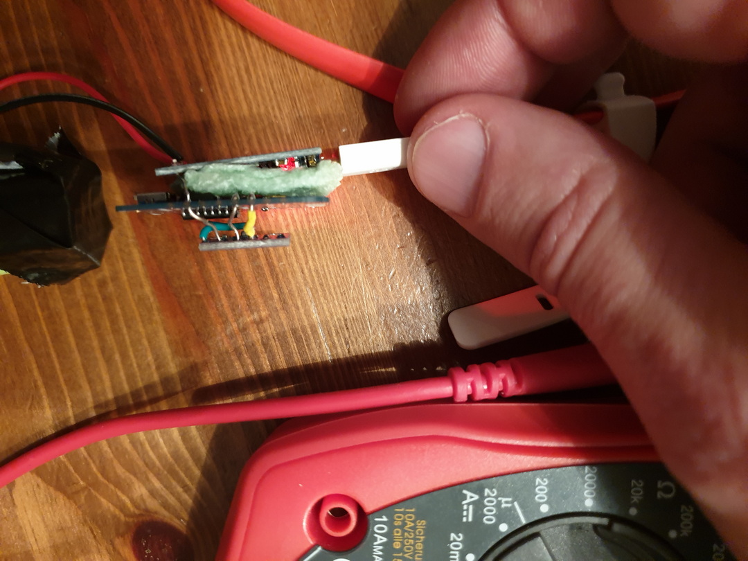
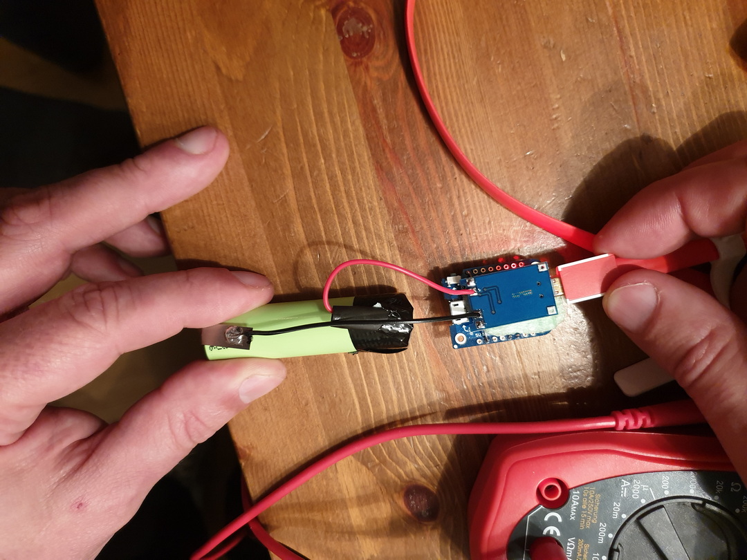
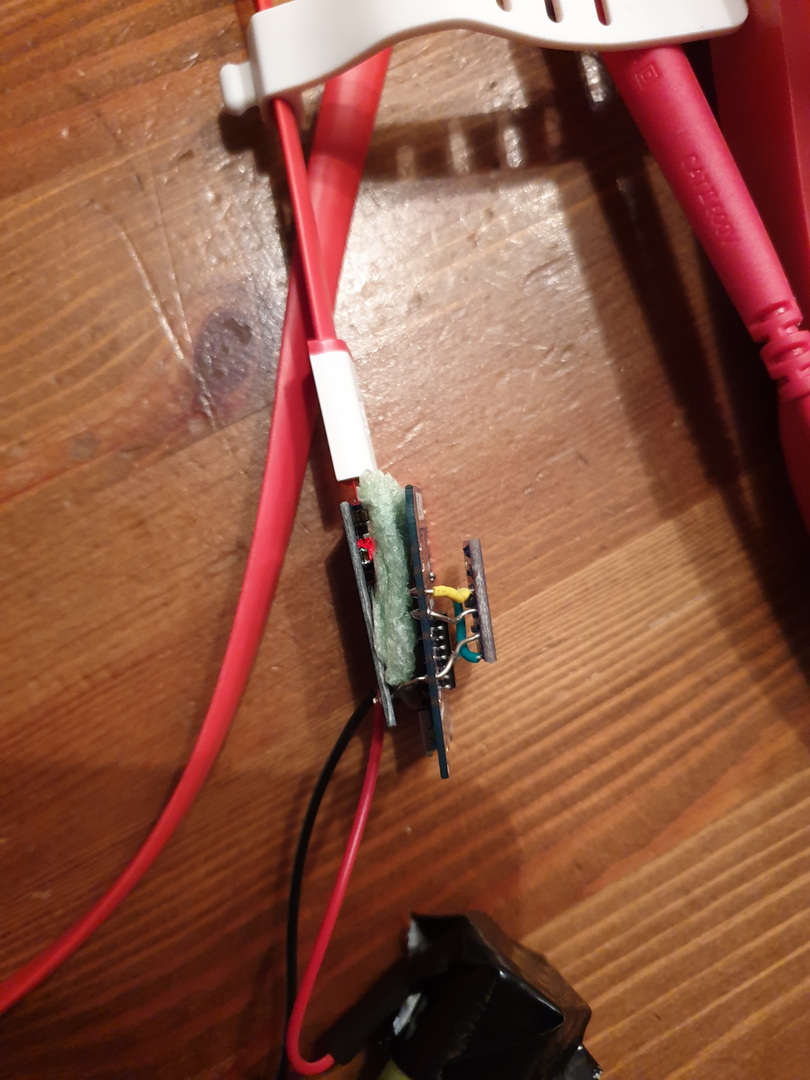
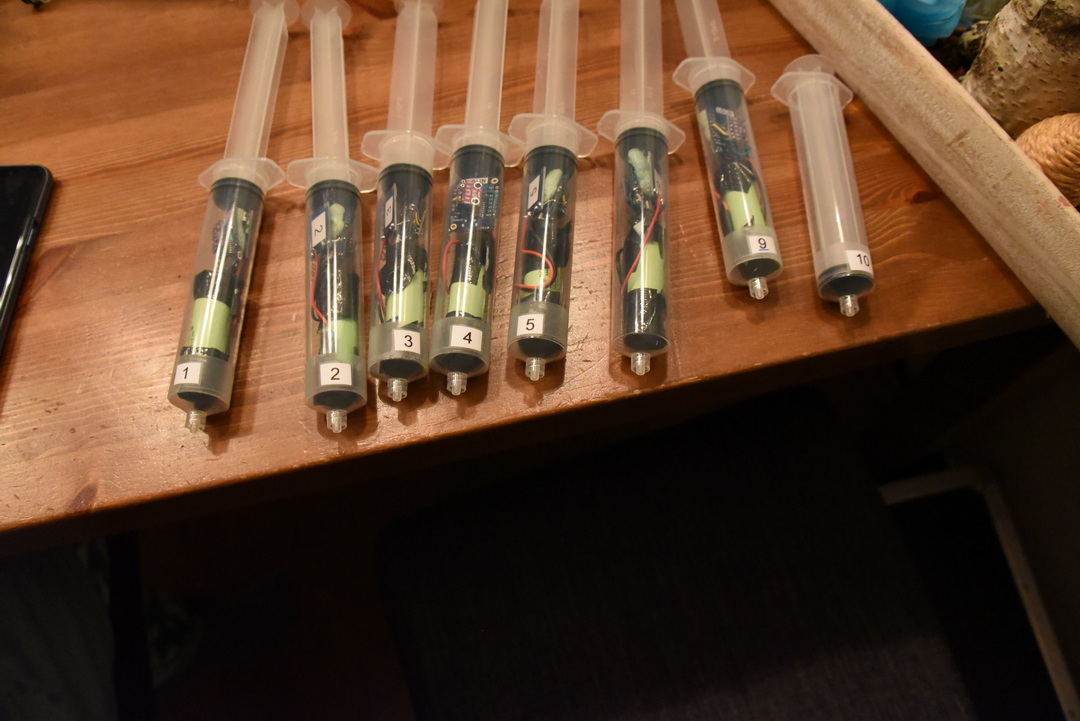
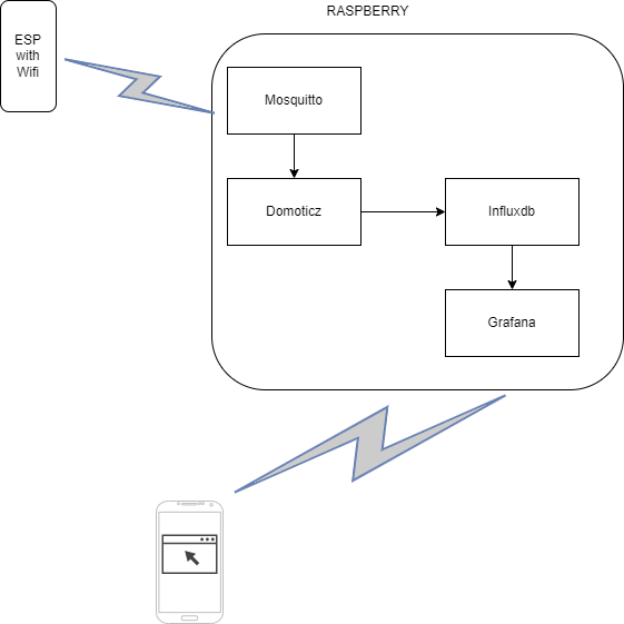
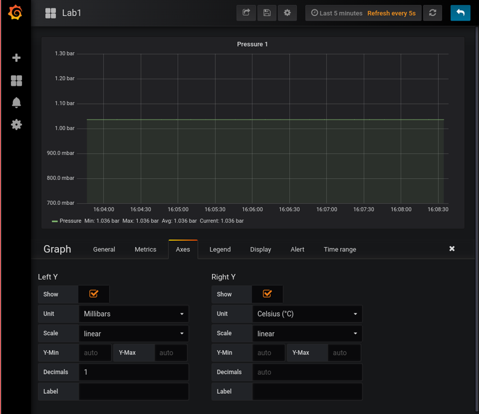
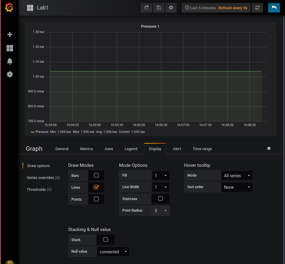
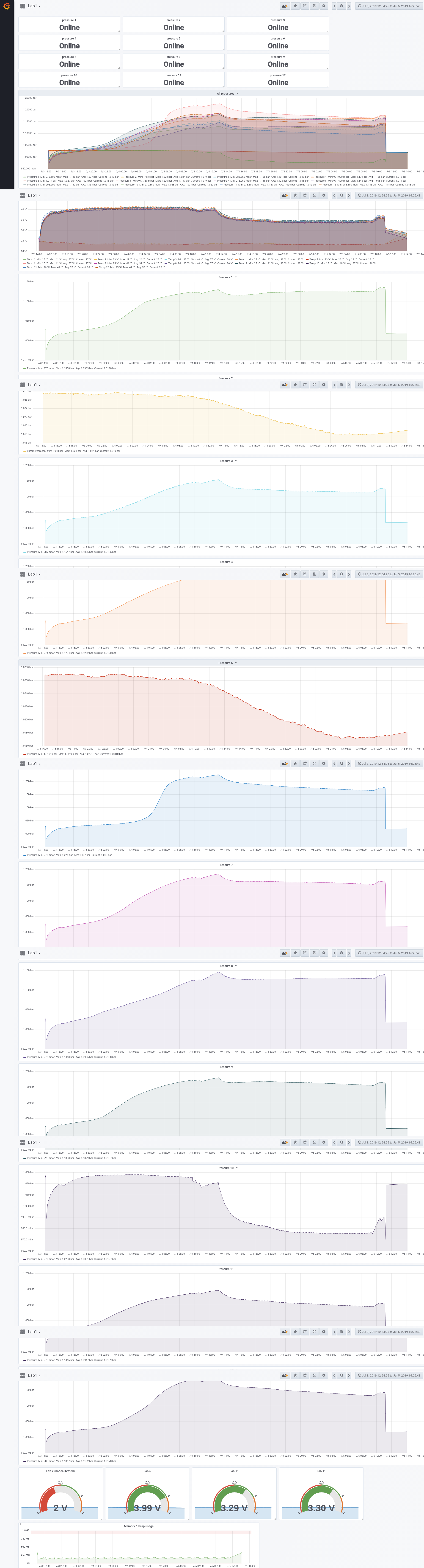
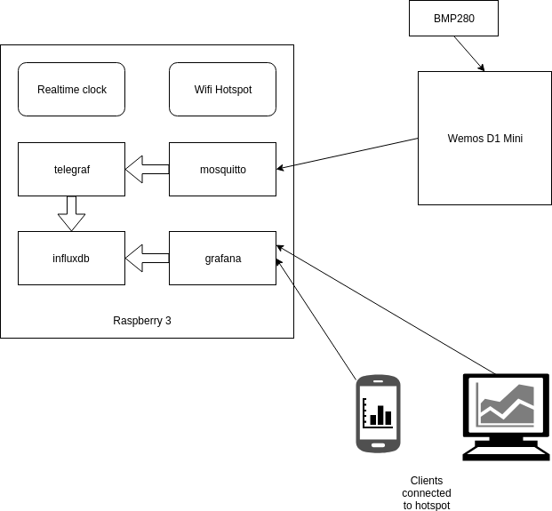
For measuring pressure in fermentation containers, I designed a pressure sensor which could be wireless connected to a fermentation container. The sensor would transmit the values to a Raspberry which was configured as a Access Point and would store the measurements and generated graphs using Grafana.
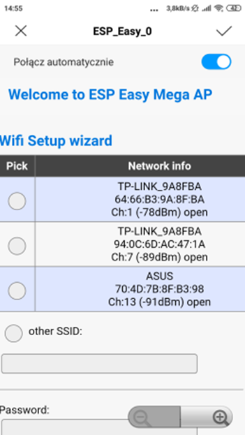
Connect esp with a power source. Look for a AP with ESP_Easy_0
Use password “configesp” to connect
Start you browser and enter http://192.168.4.1
In wifi wizard setup select “pressurespot” Enter password “pressurespot”
Press connect
Wait 20s and look in the raspberry logs which IP the ESP got.
Connect laptop/mobile to wifi “pressurespot”and connect
Enter found IP from ESP in your browser.
Proceed to main config
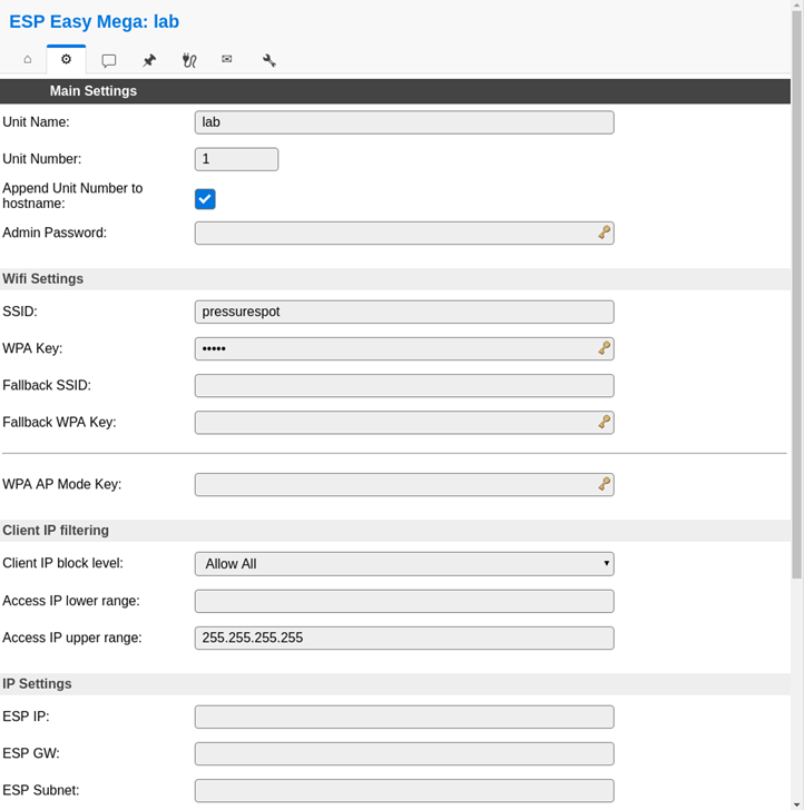
Main setting table, set the following
Unit name & number + append
SSID and WPA key pressurespot
Client IP block level allow all
Press submit
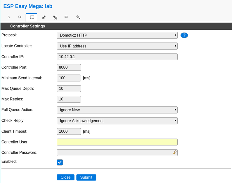
Press controller tab
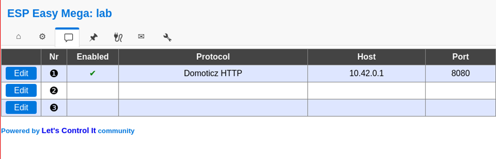
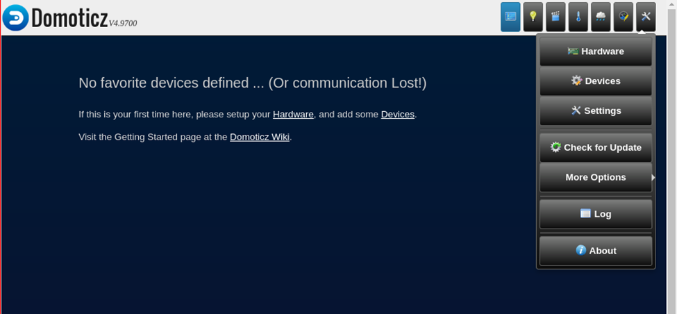
Press first edit button and set following – Protocol: domoticz http Next set – Controller IP : 10.42.0.1 – Toggle enabled and press submit
Resulting in:
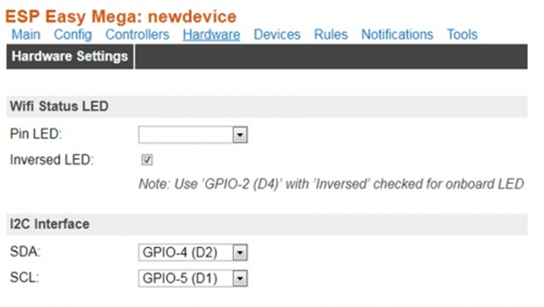
Next we got to Hardware
I2C interface switch GPIO-4 and GPIO-5
GPIO – SDA: GPIO-4 (D2) change to GPIO-5 (D1)
GPIO – SCL: GPIO-5 (D1) change to GPIO-4 (D2)
Press “Submit”
Devices TAB
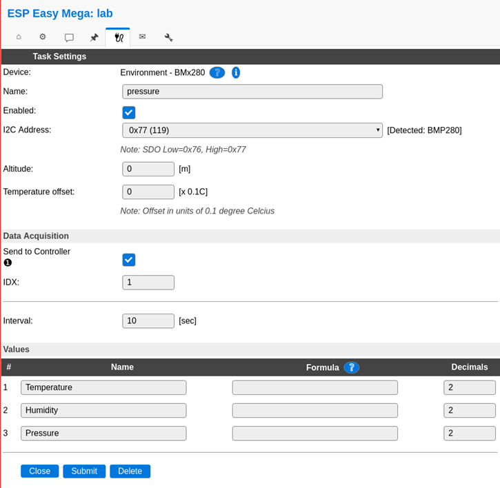
Press edit, and select device “Environment – BMx280” from the pulldown menu.
Next, set the following
Name: pressure
Enable on
I2C address : 0x76 ( Is there is no 0x76 of 0x77 .. do a i2c scan on the next tab )
Send to controller , mark this
IDX: give this the number you had given this node (this is the one you have to use in domoticz )
interval 10Seconds
and press submit
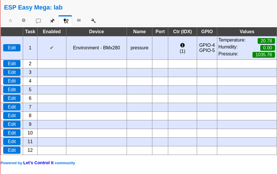
In the Devices tab, you should be able to see the sensor with the values (Temperature and pressure)
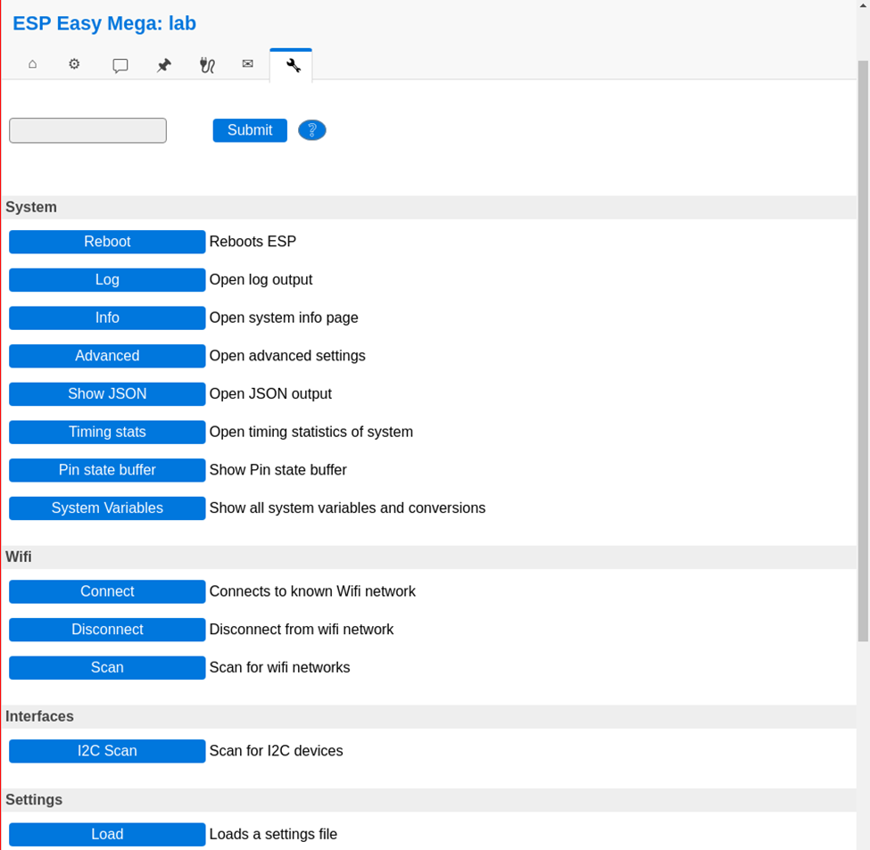
No values? Do a i2c scan and/or reboot ESP ( You can find these in the tools tab)
Tools TAB
Press I2C scan, when seeing a address like 0x76 or 0x77 use this in previous tabs. Still nothing, even after reboot? Maybe faulty hardware?
Everything okay? Back to the config tab
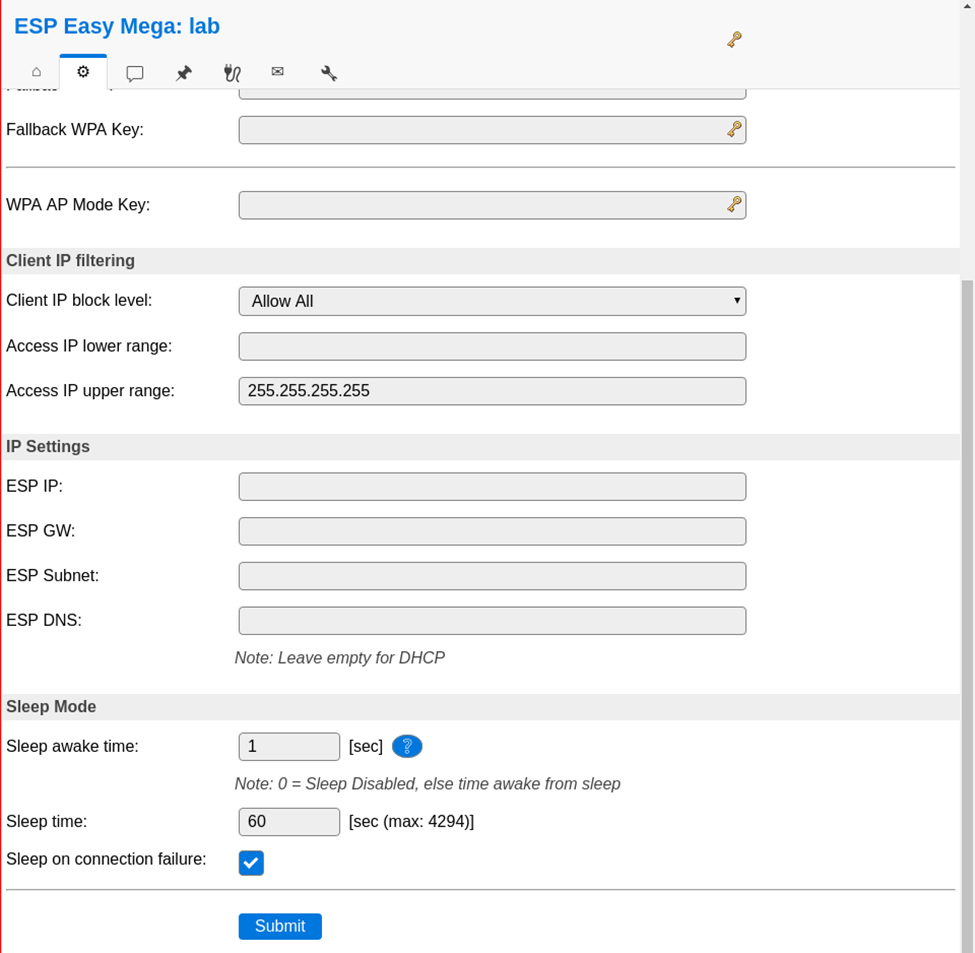
We are going to set the sleep mode. Warning ! .. when setting this it is hard to get into the config pages again. ESP will startup, connect to wifi, send values and goes to sleep again.
At the bottom set: Sleep awake time 1 sec
Buttons on the raspberry / pressurespot
Red button :
Less than 3 seconds is reboot
Longer than 3 seconds is shut down
Charger can be removed, when the green light is off
Led lights on the sensors
Red light (R2; constant): battery is charging
Blue light (R1; constant): battery is full
Blue light (R1; constant) & red light (R2; blinking): trying to charge, but no battery connected
Add shutdown script to /etc/rc.local
python /usr/local/bin/power-switch.py &
/usr/local/bin/power-switch.py
#!/usr/bin/python
import threading, subprocess
import RPi.GPIO as GPIO
def shutdown():
    subprocess.call('sudo shutdown -h now', shell=True)
def edge_detected(pin):
    if GPIO.input(pin):
        t.cancel()
        subprocess.call('sudo reboot', shell=True)
    else:
        t.start()
if __name__ == '__main__':
    try:
        GPIO.setmode(GPIO.BOARD)
        GPIO.setup(5, GPIO.IN)
        GPIO.add_event_detect(5, GPIO.BOTH, callback=edge_detected, bouncetime=10)
        t = threading.Timer(3.0, shutdown)
        while True:
            pass
    finally:
        GPIO.cleanup()
/usr/local/bin/ledoff.py
#!/usr/bin/python
import RPi.GPIO as GPIO
import time
GPIO.setmode(GPIO.BCM)
GPIO.setwarnings(False)
GPIO.setup(18,GPIO.OUT)
GPIO.output(18,GPIO.LOW)
/usr/local/bin/ledon.py
#!/usr/bin/python
import RPi.GPIO as GPIO
import time
GPIO.setmode(GPIO.BCM)
GPIO.setwarnings(False)
GPIO.setup(18,GPIO.OUT)
GPIO.output(18,GPIO.HIGH)
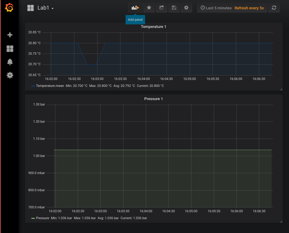
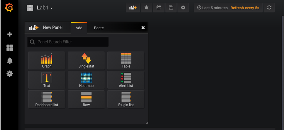
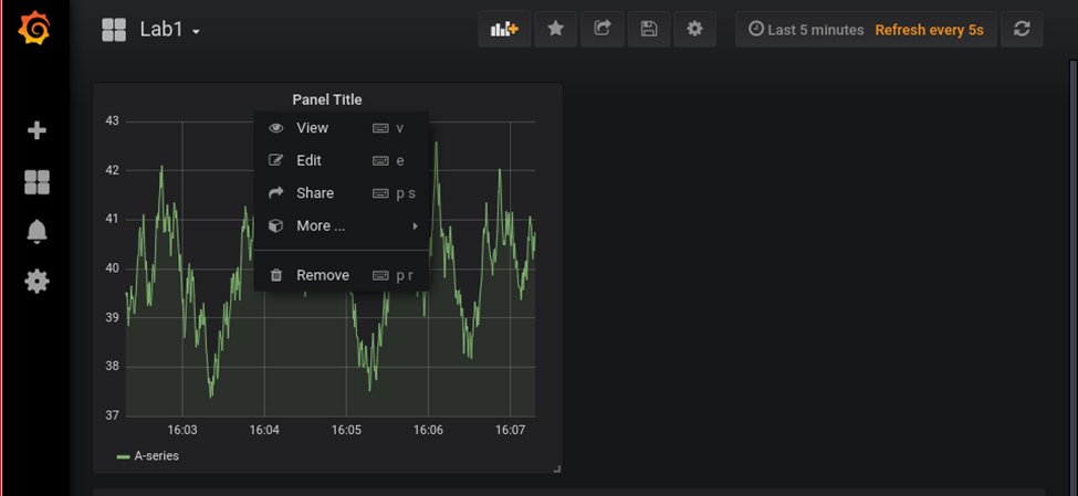
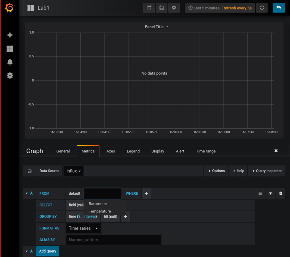
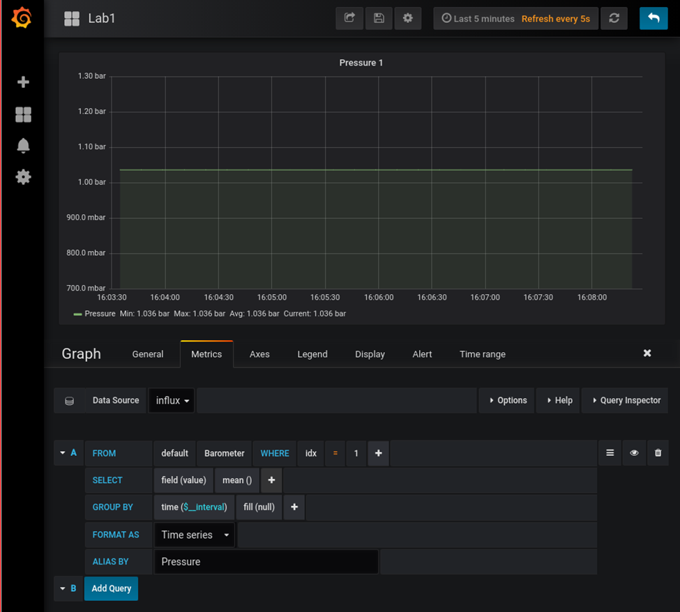
Now we can check that grafana is up by loading it in a browser: http://10.42.0.1:3000. If so, you can log in with the username and password = admin and set a new admin password.