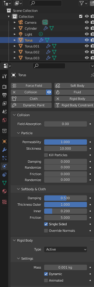
Made a blender animation with a chain which hangs on one loop. The pole is also a collision object.
I still got a problem with the chain breaking at the end of the animation.
Made a blender animation with a chain which hangs on one loop. The pole is also a collision object.
I still got a problem with the chain breaking at the end of the animation.
Today i talked about creating apps for mobiles with a colleague.
I made me wonder what programming IDE i’ve used in the past.
Things i’ve made:
Tools used:
App ideas, not started or not completed:
Downloads and screenshots:

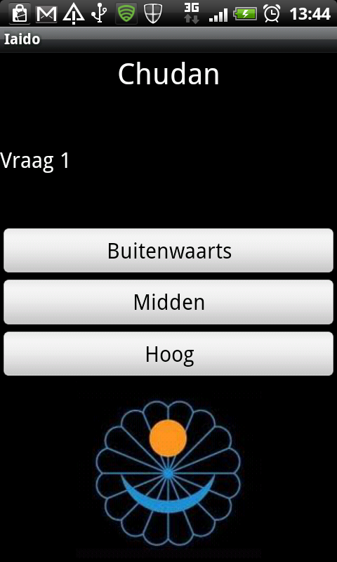
I’ll post more/better examples
Other:
Reversed engineered a tool found on a ‘hackers’ phone.
Apparently it was a security test setup nobody was aware of.
I was able to find urls and domains where some call-home functionality was involved.
For my post about creating 360 degrees sphere photo’s i made a little animation using blender.
Learned a lot again.
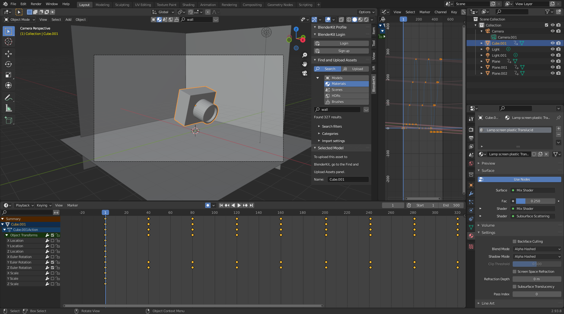
Final animation:
Started a test with opnsense, my other test is utilizing some Mikrotik’s with firewalling.
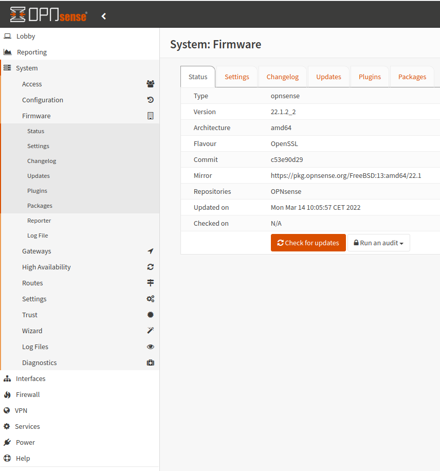
Will post my findings below .. hold on
After many years Domoticz, tried Home Assistant … again.
Going to test this instance, running on a NUC, besides my production setup. Time will tell.
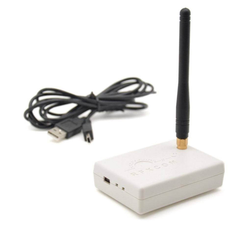
I’ve got a RFXCOM connected to my domoticz, and i wanted to share my 433Mhz devices also in HA, so i configured ser2net.
On domoticz server
apt-get install ser2net
append

10001:raw:0:/dev/ttyUSB0:38400 NONE 1STOPBIT 8DATABITS max-connections=3
to /etc/ser2net.conf

Better is using by-id instead of ttyUSB

Find yours
find /dev/ -type l -iname *RFX*

(/dev/serial/by-id/usb-RFXCOM_RFXtrx433_A11ZKXF0-if00-port0)
Domotics
Example

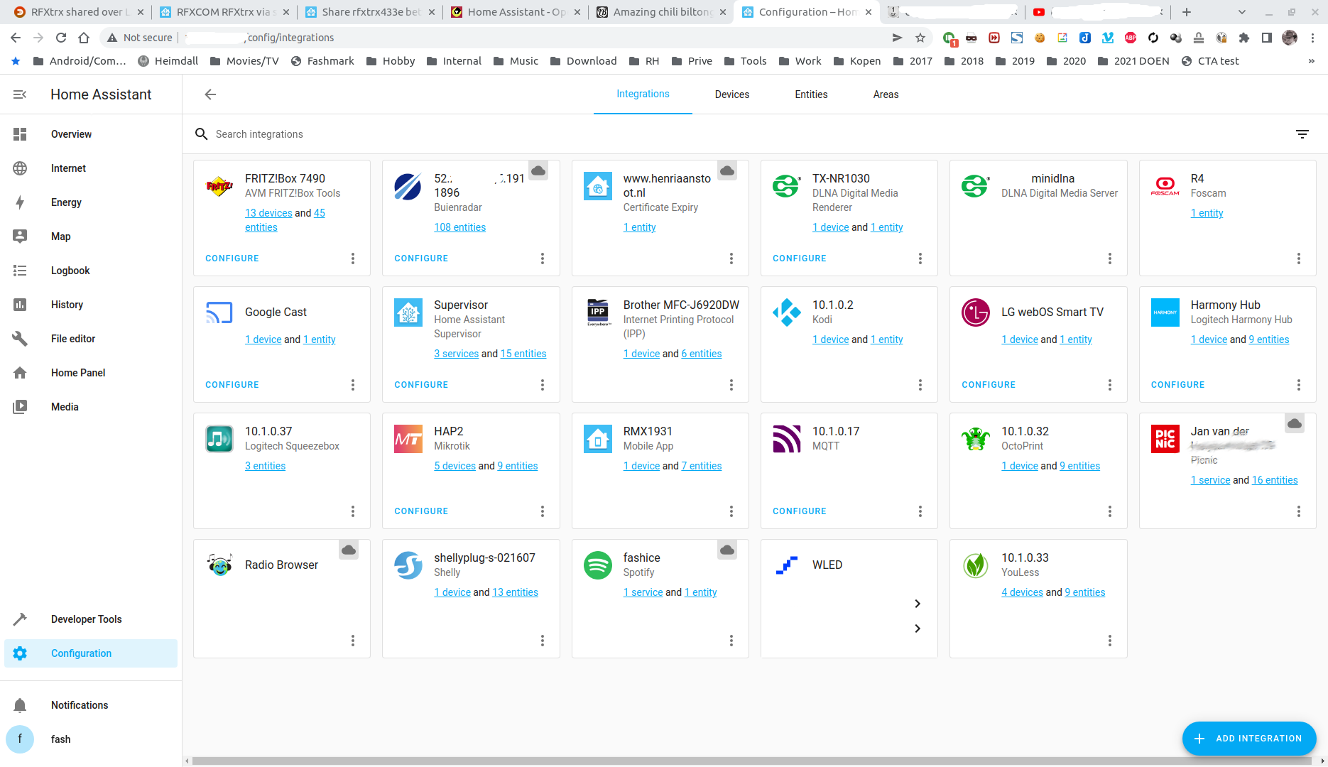
Home Assistant
Add intergration “RFXTRX” , select LAN, input your domoticz IP and port 10001
Takes a while to populate the devices.
I’ve still have to find a way to add a second RFXCOM
RFXCOM
IP Blocked fix (Locked myself out .. Remove contents in this file.)
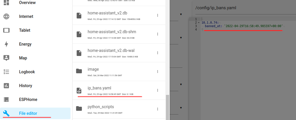
Using SSH
➜  ~ find / | grep ip_ban
/config/ip_bans.yaml
➜  ~ vi /config/ip_bans.yaml
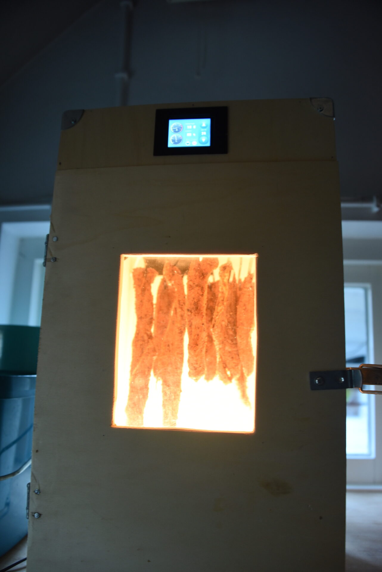
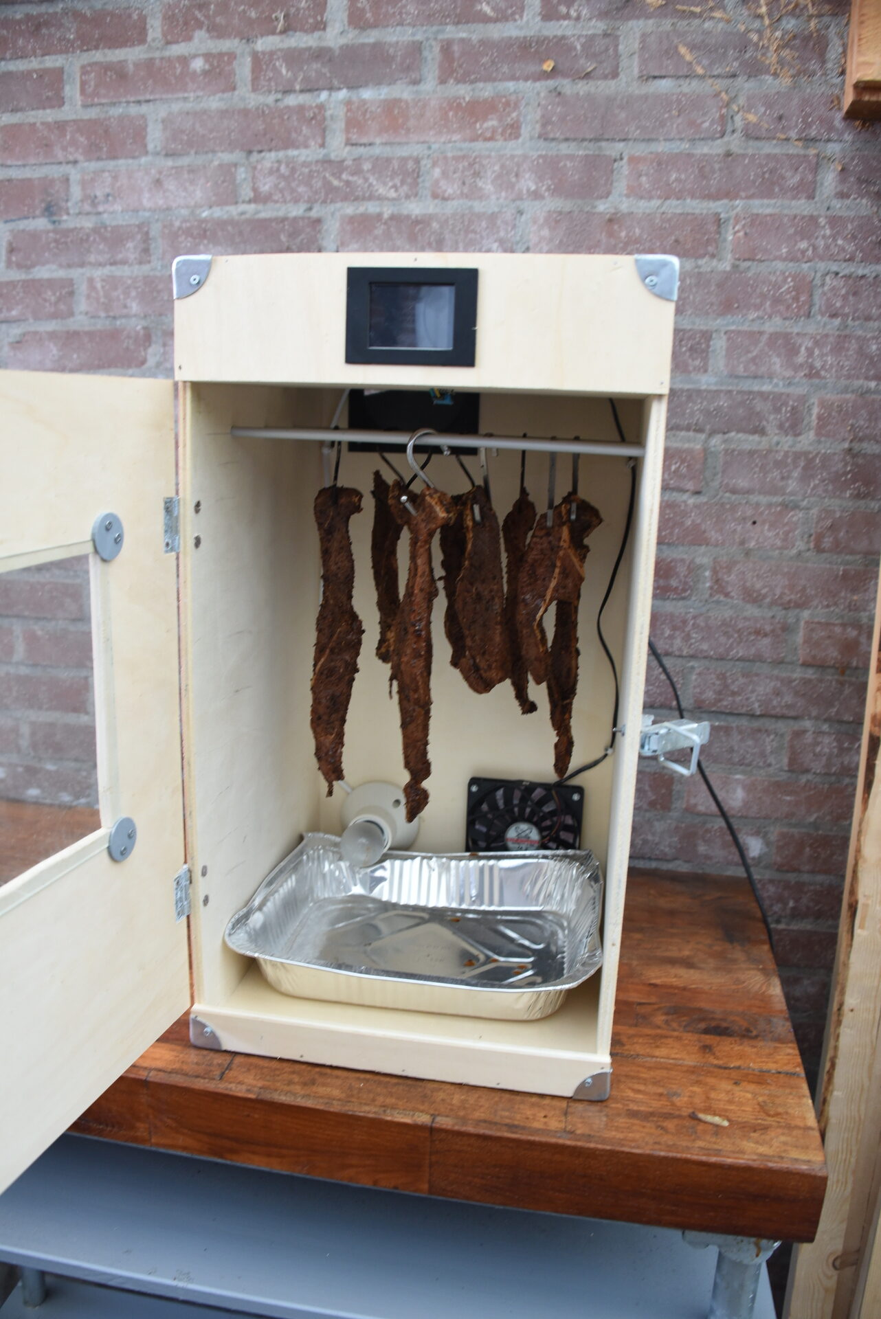
In 2020 i made a Biltong drying thingy, using a Nextion and a Arduino.
Today i’m preparing for some Chilli Biltong, which i’m going to put in the drying box tomorrow.
Arduino functionality
Recipe
Meat
1 kg Beef Cut into 1.5cm - 2cm steak slices

Spice
2 tbsp black pepper coarsely ground.
2 tbsp course Sea Salt
1/2 tbsp smoked paprika
4 tbsp coriander seeds roasted and coarsely ground.
1 tbsp chili flakes

Marinade
50 ml worcestershire sauce
100 ml apple vinegar
1 tbsp tabasco sauce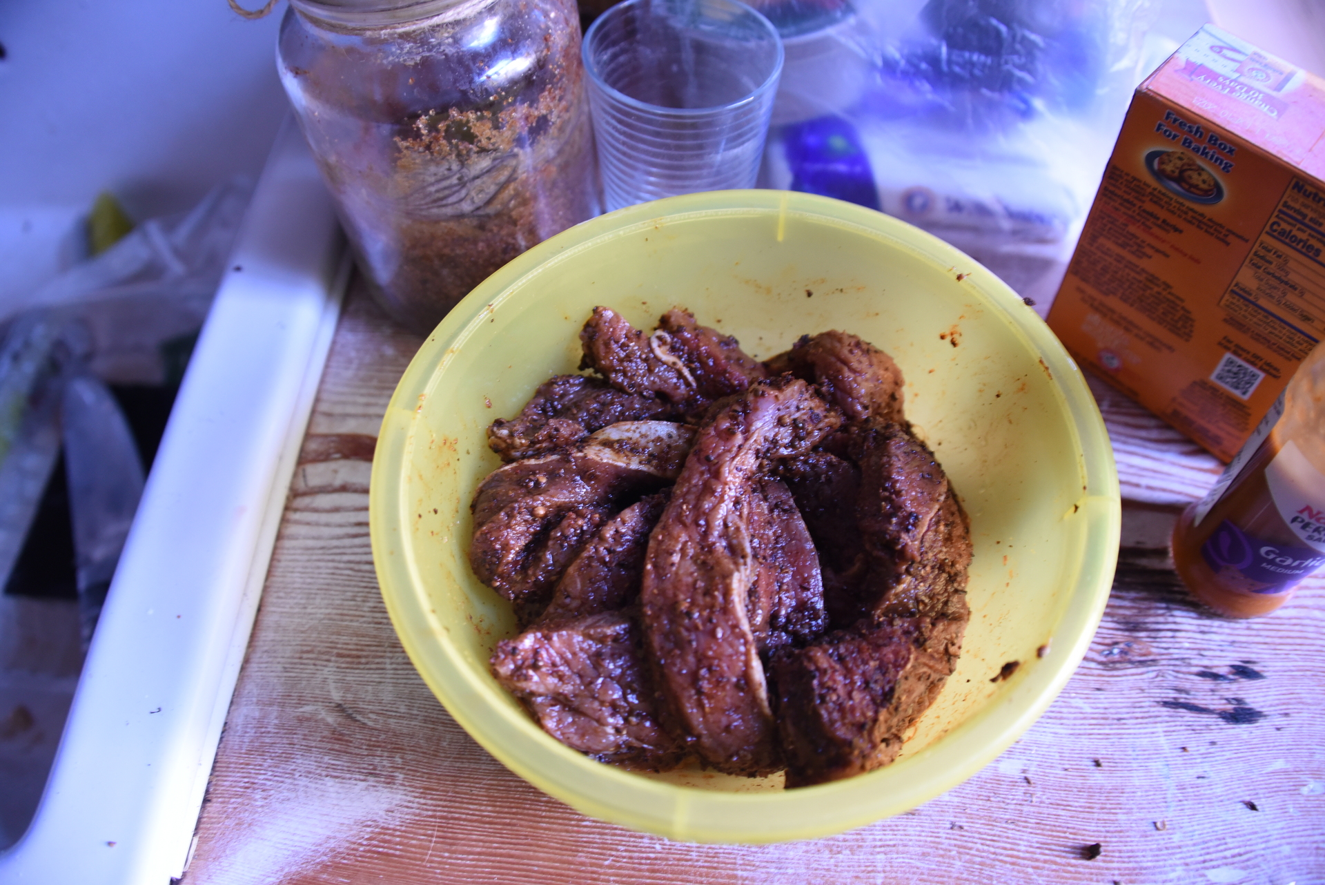
Script – get images from Reolink cam
while true; do
wget "http://ip.number.or.hostname/cgi-bin/api.cgi?cmd=Snap&channel=0&rs=123asd&user=admin&password=MYSECRETPASS" -O $(date +%Y%m%d%H%M).jpg
sleep 60
done
Script to generate MP4 (60fps)
cat *.jpg | ffmpeg -f image2pipe -r 60 -vcodec mjpeg -i - -vcodec libx264 out.mp4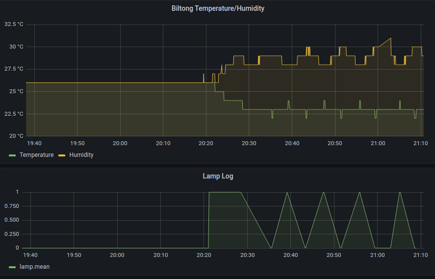
I’ve took it offline, maybe someone wants the source code and database.
It was much fun, time to move on.
UPDATE: 20230228 – It is online again.
(I’ve got some mails and mentions in music forums)
https://pipetunesearch.henriaanstoot.nl/
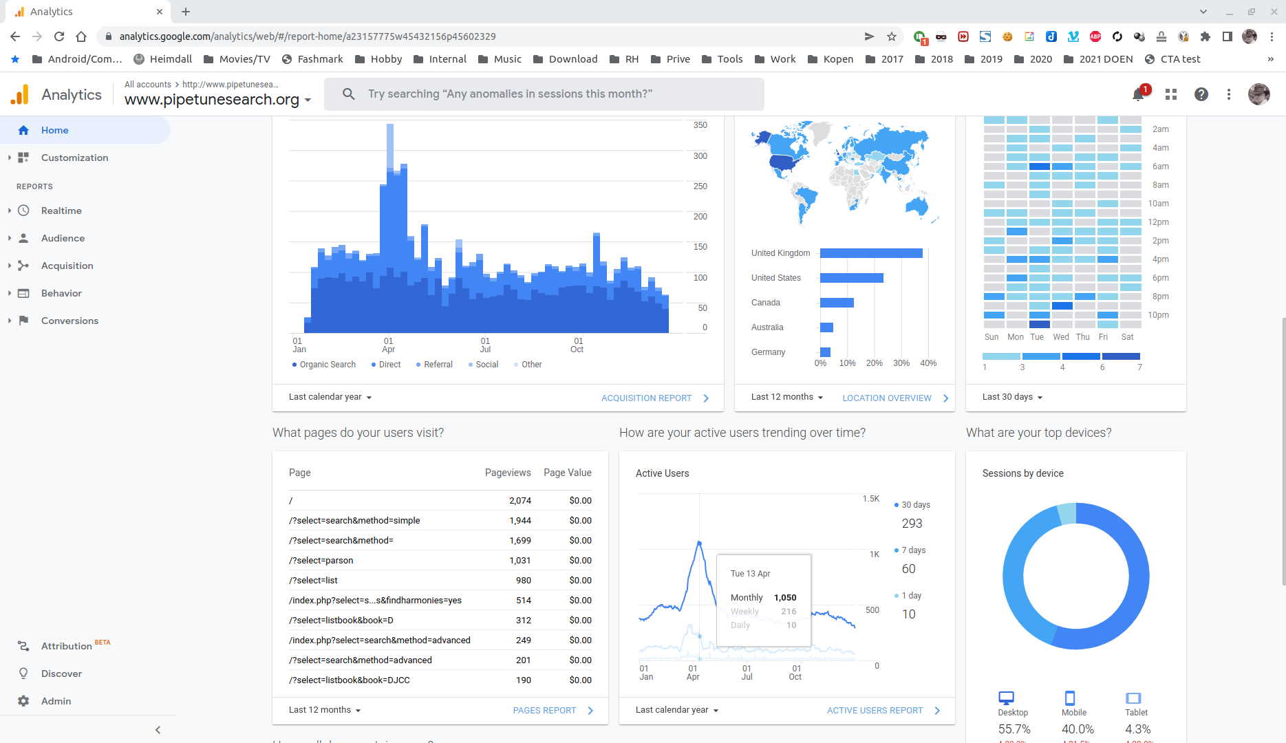
At least i’ve got some nice reactions
I’ve create my own bww/bwm to parsons code convertor.
Rest of the website is php, mysql … first one started in 2001 using php3, until php7.
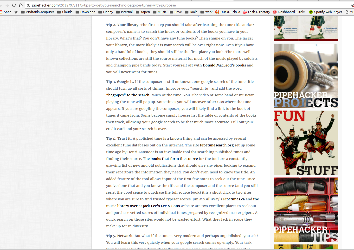
PARSONS CODE: OMG, you don’t know how long I have been waiting for a search engine to find tunes in my head. I thought about creating some kind of dictionary based on theme notes, or searching through bww files for sequences. What a thrill to find your site. I just hum a tune, use the up, down, repeat letters and… like magic the title is found. You are a genius. I will never be stumped for a title again. Thanks so much, John
Other successes i’ve heard of are: 2 Youtube movies being identified, a nameless bww file and mp3’s
Mail from Dave:
Hiya
My name is Dave Mason. I put a few tunes together a few years ago called "Tummle Yer Wilkies" which, I see, gets mention on your website. However, I see that you're not sure where people can access the tunes.
Well, the book is free to download from https://sites.google.com/site/tummleyerwilkies/home and I hope to have volume 2, "Tummle Yer Wilkies Too!" uploaded in the near future.
Cheers
Dave Mason
Geneva, Switzerland.
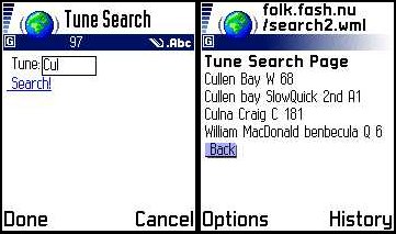
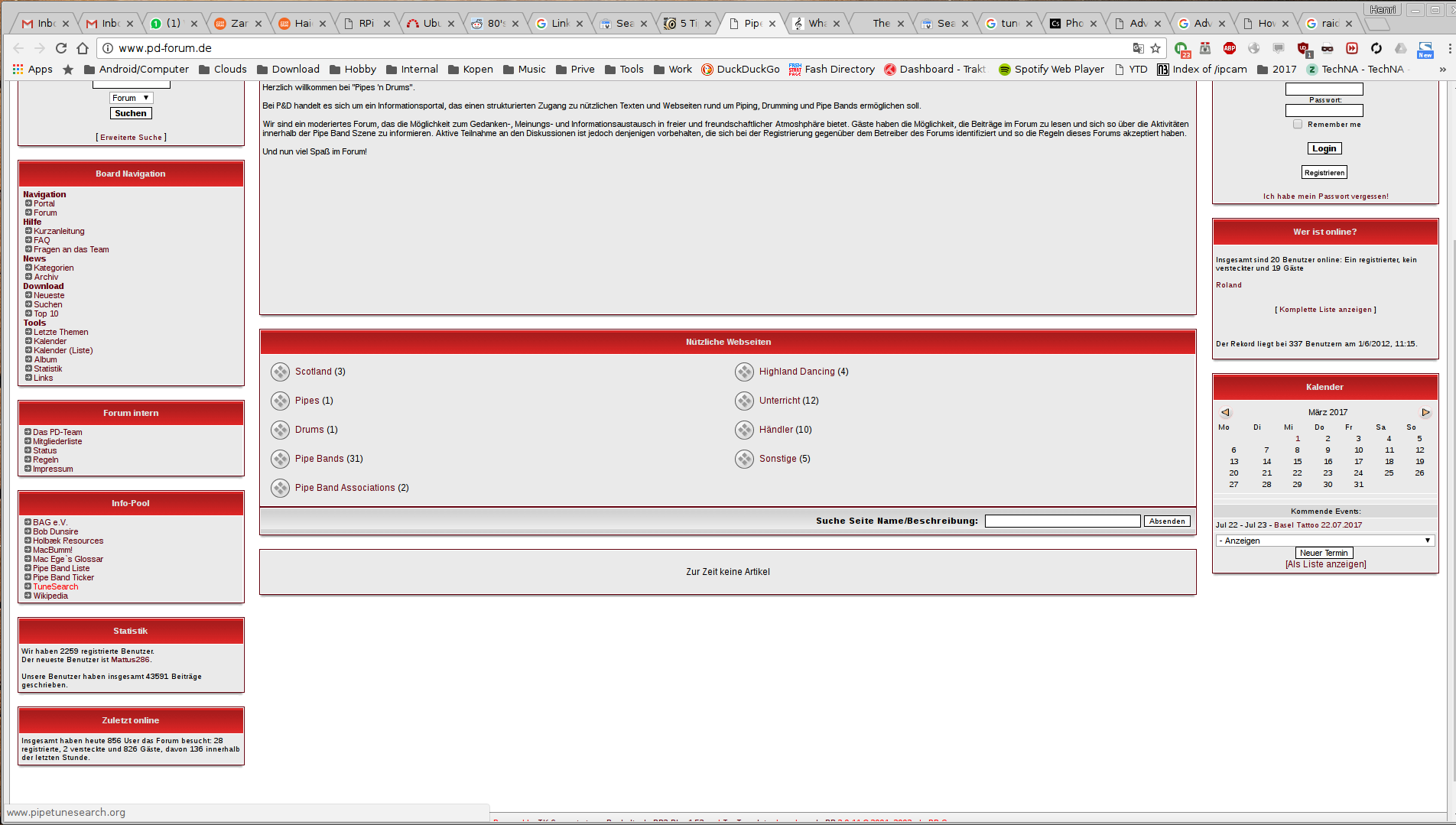
NEW - Palm version by Andreas Joebges (updated)
Added stuff changed software
Added parts in booklist and search.
Additions to www.drumscoresearch.org
Many additions by: Chris MacKnight
Palm version by Andreas Joebges
Added index send by : Henning
sat 14 feb: Installed DB on macbumm's site
sun 15 feb: Made some changes, limit search and layout
Removed own collections from DB
Expanded statspage with jig/hornp/march/etc.
mon 16 feb: Imported College of Piping index i got from Ralf .. (thanks!)
Imported Irish Tunes for Warpipe
Added Log, Fixed Members Login for edit purposes
tue 17 feb: Layout, testing new functions
wed 18 feb: Imported Bagpipe Music - John MacFadyen
thu 19 feb: Uploaded some Book Covers,
programmed a export-to-xls function, so you can use the
DB data yourself (bottom of booklist pages)
Imported Gordon Highlanders Vol 1
sat 21 feb: Fixed m?c and l*ken search
Imported Gordon Highlanders Vol 2
Added AKA search
Old search request stays in search field
Added some covers
code cleanup
mon 23 feb: Fixed bookcover popup
Imported Mark Saul Vol I
Uploaded Mark Saul Cover II and changed faulty cover other Vol
Bookinfo added ISBN, Price, etc. Suggestion i got by Email
Uploaded Queens Own Highlanders The Pipers Day
Imported Seaforth Highlanders - Standard Settings
thu 26 feb: DB cleanup
Added Code
Imported Donald MacLeod vol 1 2 and 4
fri 27 feb: 1st editor assigned - Henny Barnhoorn
sat 28 feb: Imported Vol 5 and 6 Donald MacLeod
sun 29 feb: CD Information added
2nd editor - Coline Gerritsen
mon 01 feb: Added CDs .. Thanks Coline
Gordon Highlanders Book 1 checked/added/etc. by Henny .. thanks
CD displaying code changed
Imported Robert Mathieson Book 4 (now over 4000 tunes in DB!)
fri 05 mar: Added CDs
Altered ShowCD Code
sun 07 mar: Imported some books (NOW 50!)
Henny Completed reediting Gordon Highlanders Vol2
Add MP3 clip code in cdinfo
mon 08 mar: Imported book
Fixed image caching for faulty browsers
Search finds composers also
Fixed Menu structure
Added Templates
tue 09 mar: Added link under advanced search - find ALL harmonies. :)
wed 10 mar: Added book with cover + MP3 sample
thu 11 mar: Imported Piob. CD
Added edit icon help
fri 12 mar: Find tunes on CD in beta test .. :)
(click search -> advanced .. enter a keyword, mark the media
checkbox and click search .. CDs found at bottom of page .. :)
sat 13 mar: Imported another filled-in cd-template :)
Added some covers
wed 17 mar: Added 15 Piobaireachd Society Volumes
sat 20 mar: Added 3 CD's
tue 23 mar: Added several books (5166 tunes now!) Thanks John
thu 25 mar: Changed code, checked book, imported book
tue 30 mar: Uploaded covers, edited book (Murray Blairs) and added books
till
tue 06 apr: Uploaded Covers, Added books, Changed code
till
sat 17 apr: Imported some books, added parts to export-excell
(will be in search later)
Henny checked/edited some books
tue 20 apr: Imported books, testing query caching for speed improvement.
(yes getting kindda large .. this thingy)
thu 22 apr: 100! BOOKs!
--missing log--
Added book, covers e.t.c.
sun 11 jul: Added Battlefield Book (thanx Markus)
mon 11 jan: Added 2 books (thanx again Markus)

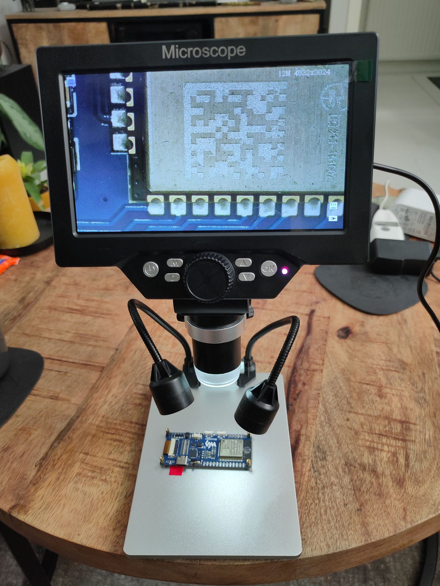
Update: 20220829 – Microscope G1200
Tools:
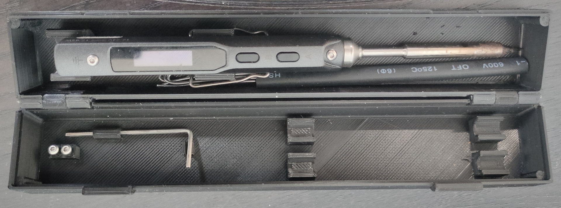

Bought some boxes for chips
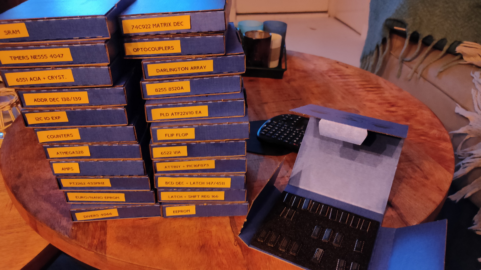
Fun .. but do i need it?
HackRF One

HackRF One from Great Scott Gadgets is a Software Defined Radio peripheral capable of transmission or reception of radio signals from 1 MHz to 6 GHz. Designed to enable test and development of modern and next generation radio technologies, HackRF One is an open source hardware platform that can be used as a USB peripheral or programmed for stand-alone operation.
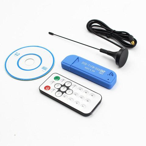
I’ve got dvb alternative below now. Hackrf cannot be bought anymore
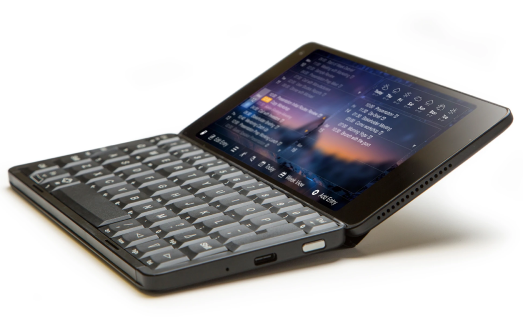
Gemini PDA
ALTAIR 8800 EMULATOR KIT
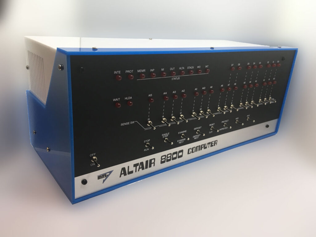
The Altair 8800 is a microcomputer designed in 1974 and based on the intel 8080 CPU. Using only switches to program and leds for output.
Even my DIY build computer has a hex keyboard input and 7segments display.
Omnicharge 20+ Usb C Wireless Power Bank 20,000mAh Power Delivery 3.0 + Quick Charge 3.0
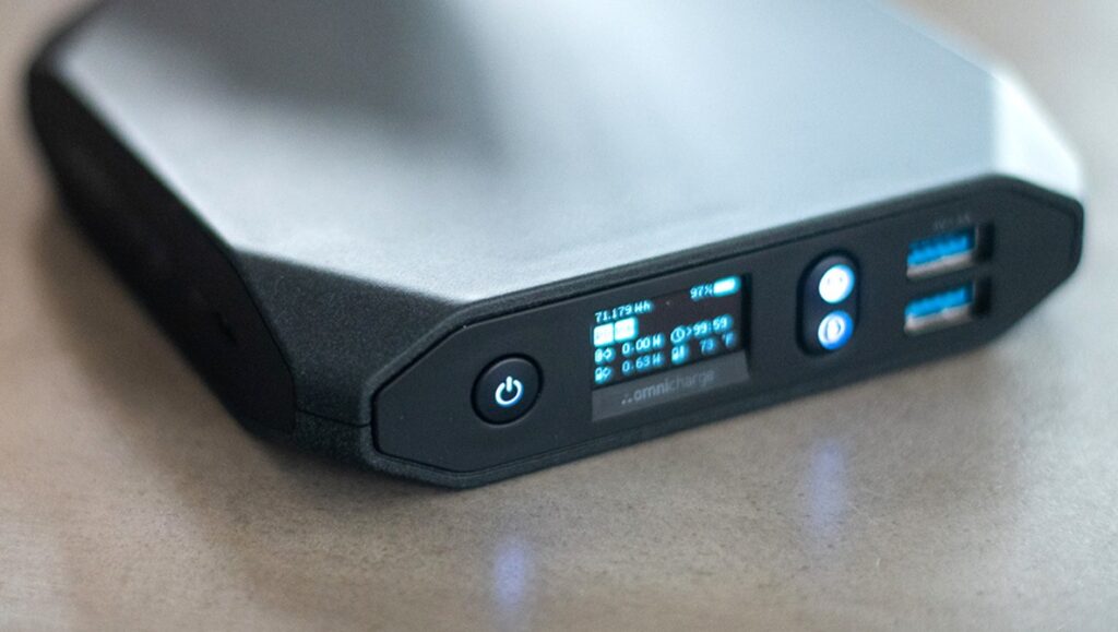
You can use this as a mobile soldering station using a TS100 soldering iron.

Rigol Oscilloscope DS1054

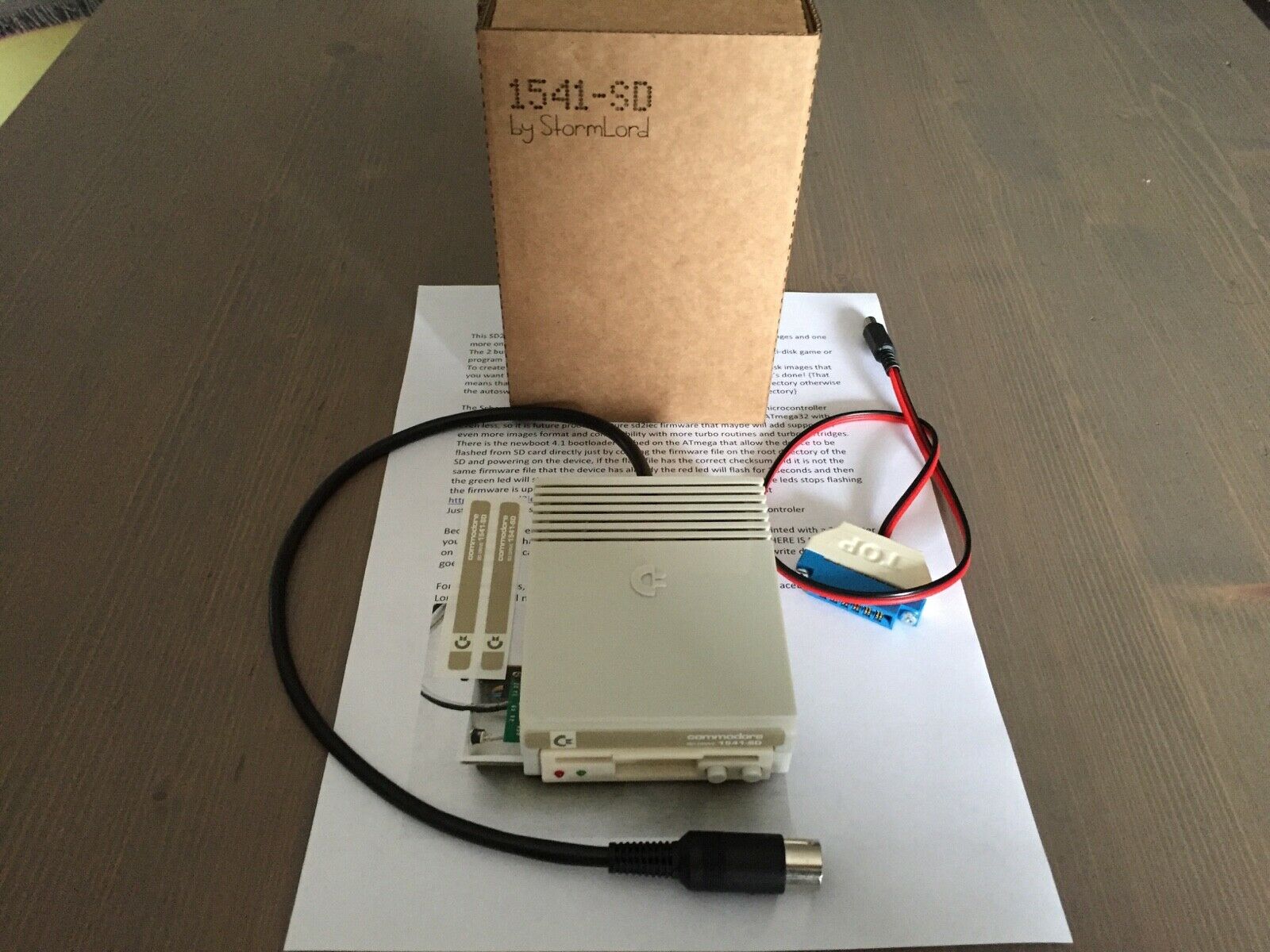
SDCard reader for C64 and other commodore machines
Got this one now, superb. And a Meatloaf DIY
Tv Stick Dab Fm Dvb-t RTL2832 R820T Sdr RTL-SDR Dongle Stick Digitale Tv Tuner Ontvanger TVSDVBS816
Update : got this one, review later on.
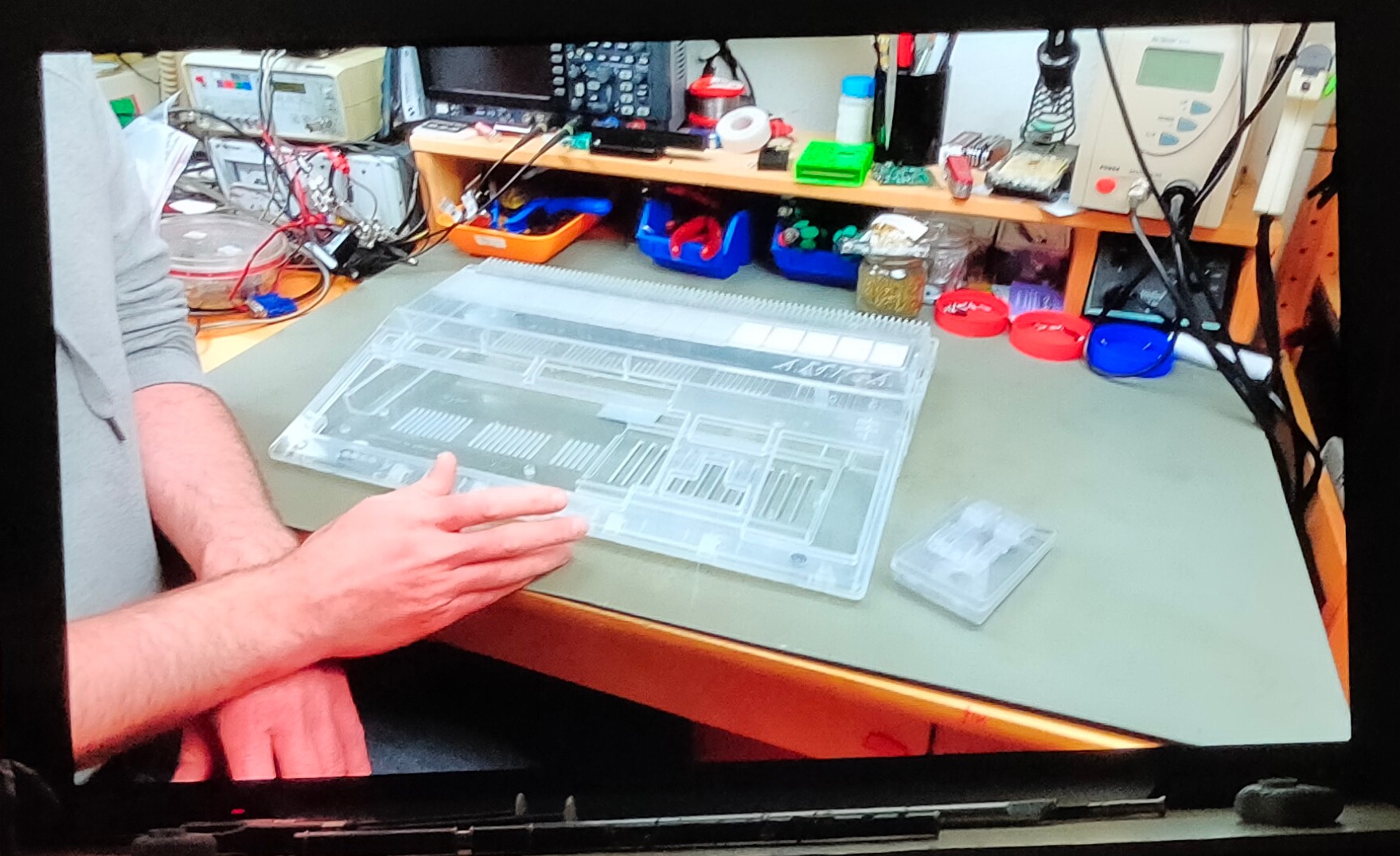
Clear case for amiga and tank mouse