I was not happy with my old setup to control all media devices in my living room.
Controlling all devices using a single button and automations was not easy.
Problems encountered :
- Switching from one device to another toggled a device used by both.
- Switching from TV to Spotify (using my Onkyo), turned off the TV and cec turned off the Onkyo
- Using the Home Assistant Onkyo integration, I could select NET but not NET>Spotify
- The Harmony hub I’m using for Infrared Control didn’t expose all buttons.
- My Set-top box only power toggles. No way of reading the state.
Addressing problems:
Number 1 & 2 : Disable CEC, and manual add all that cec tried to do for me. (https://en.wikipedia.org/wiki/Consumer_Electronics_Control)
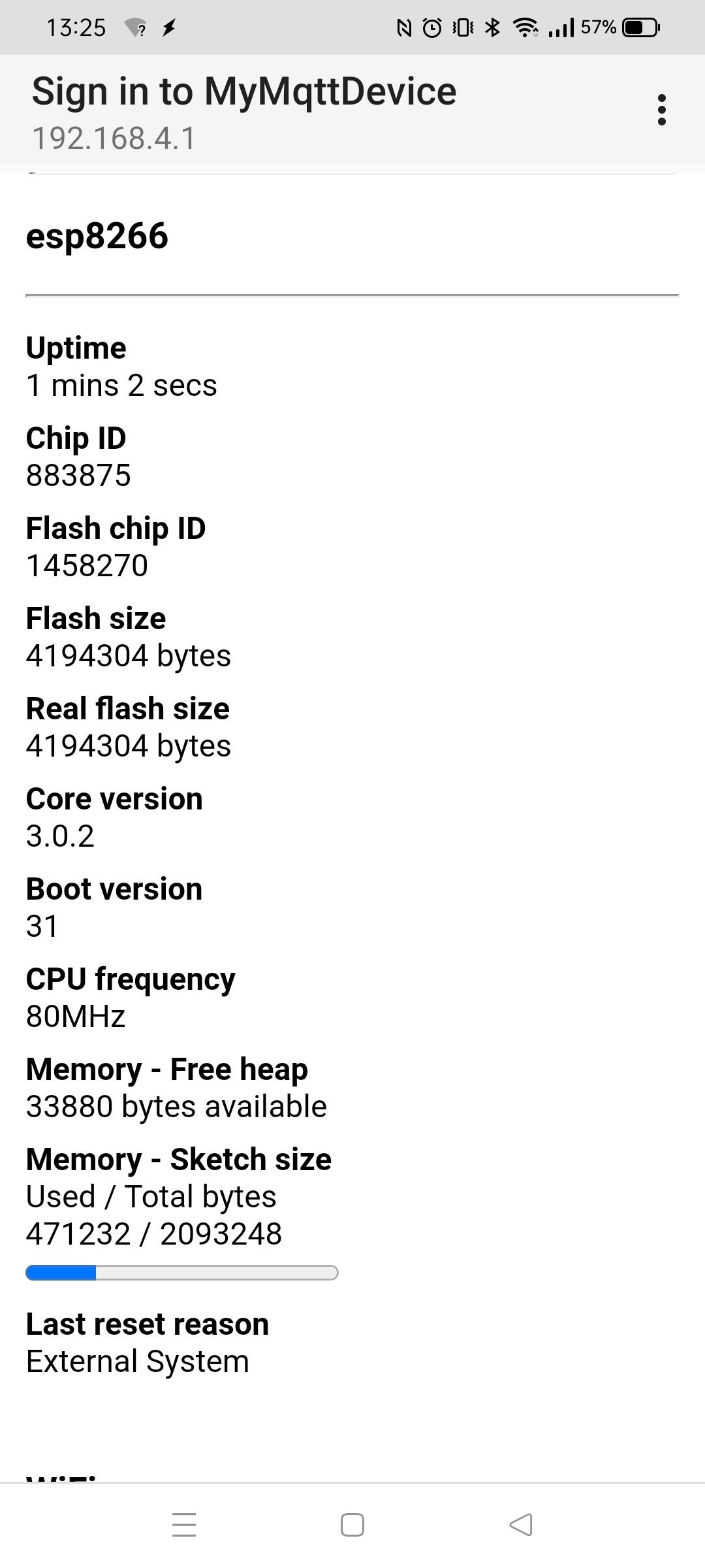
Number 5 :
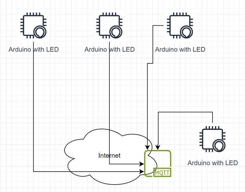
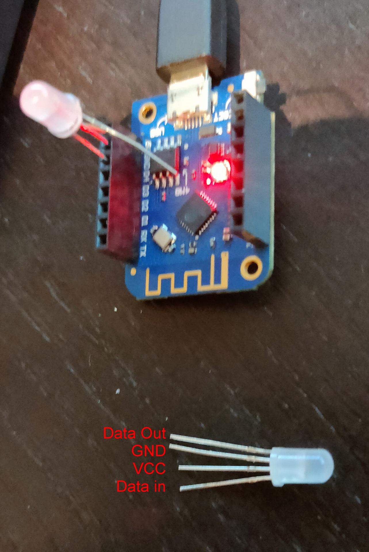
(See post : https://www.henriaanstoot.nl/2024/04/01/multipurpose-rgb-sensor-esphome/)
Number 3 & 4 : Two options, integrate my web controller for onkyo.
(https://www.henriaanstoot.nl/2009/10/23/onkyo-web-control-hack/)
Or give HA more functionality.
Lets add an Onkyo python script to HA.
Open a webterminal and enter following command
pip install onkyo-eiscpThis will give you:
(Hint: want to copy text from the web terminal? Hold shift while selecting text)
➜  ~ pip install onkyo-eiscp
Looking in indexes: https://pypi.org/simple, https://wheels.home-assistant.io/musllinux-index/
Collecting onkyo-eiscp
  Downloading https://wheels.home-assistant.io/musllinux-index/onkyo_eiscp-1.2.7-py3-none-any.whl.metadata (9.9 kB)
Collecting docopt>=0.4.1 (from onkyo-eiscp)
  Downloading https://wheels.home-assistant.io/musllinux-index/docopt-0.6.2-py2.py3-none-any.whl.metadata (17 kB)
Collecting netifaces (from onkyo-eiscp)
  Downloading https://wheels.home-assistant.io/musllinux-index/netifaces-0.11.0-cp311-cp311-musllinux_1_2_x86_64.whl.metadata (8.9 kB)
Downloading https://wheels.home-assistant.io/musllinux-index/onkyo_eiscp-1.2.7-py3-none-any.whl (45 kB)
   ━━━━━━━━━ 45.7/45.7 27.8     eta 0:00:00
             kB        MB/s
Downloading https://wheels.home-assistant.io/musllinux-index/docopt-0.6.2-py2.py3-none-any.whl (13 kB)
Downloading https://wheels.home-assistant.io/musllinux-index/netifaces-0.11.0-cp311-cp311-musllinux_1_2_x86_64.whl (13 kB)
Installing collected packages: netifaces, docopt, onkyo-eiscp
Successfully installed docopt-0.6.2 netifaces-0.11.0 onkyo-eiscp-1.2.7
WARNING: Running pip as the 'root' user can result in broken permissions and conflicting behaviour with the system package manager. It is recommended to use a virtual environment instead: https://pip.pypa.io/warnings/venv
➜  ~ onkyo
Usage:
  onkyo [--host <host>] [--port <port>]
        [--all] [--name <name>] [--id <identifier>]
        [--verbose | -v]... [--quiet | -q]... <command>...
  onkyo --discover
  onkyo --help-commands [<zone> <command>]
  onkyo -h | --help
➜  ~ which onkyo
/usr/bin/onkyo
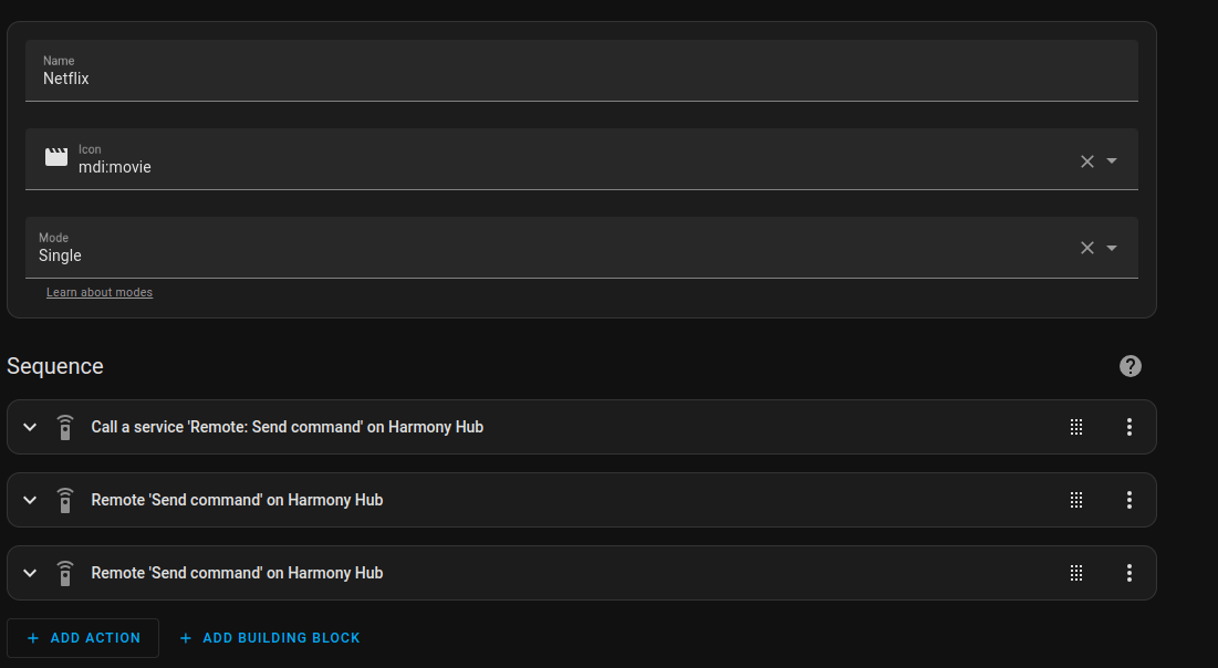
Now we can integrate shell commands in HA!
NET > Spotify
onkyo --host 192.168.1.2 NSV0A0

Spotify > track info
onkyo --host 192.168.1.2 NTIQSTN

Spotify > Artist
onkyo --host 192.168.1.2 NATQSTN

Turn Onkyo ON/OFF
onkyo --host 192.168.1.2 PWR01
onkyo --host 192.168.1.2 PWR00

Get Power state
onkyo --host 192.168.1.2 PWRQSTN

Mute on/off
onkyo --host 192.168.1.2 AMT01 or AMT00

Volume Level
onkyo --host 192.168.1.2 MVLQSTN
Home Assistant Shell Command example
  - platform: command_line
    switches:
      onkyo_mute:
        command_on: "/usr/bin/onkyo --host 192.168.1.2 AMT00"
        command_off: "/usr/bin/onkyo --host 192.168.1.2 AMT01"
Getting album art:
Get image from below url.
Note! .. its a static non refreshing image!
http://192.168.1.2/album_art.cgi
Note: This gives me a file which shows fine in a browser, but being a http feed you cannot embed this in a https site.
Another ‘problem’ with this image is that it includes headers, rendering this a invalid jpg when processing!
(remove first 3 lines programmatically)
I also want to have it updated, so I could make a mjpeg streamer for this.
Probably i’m going to use my reverse proxy which uses SSL offloading to access cover art over https.
(Then I can push this cover image on this webblog so you guys can see what we are listing to)
Another idea is to push this to an arduino display.
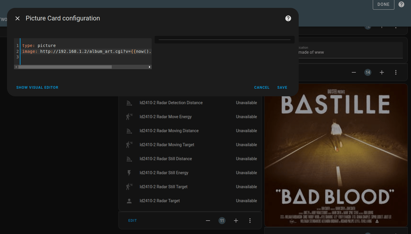
Not using https?
You can embed the album art in a dashboard. This won’t refresh, but the added time code will stop caching problems.
type: picture<br>image: http://192.168.1.2/album_art.cgi?v={{now().timestamp()|int }}")
Todo:
Make the automations foolproof.
Watching TV and want to listen to Spotify?
- Turn TV off
- Switch Onkyo to Net and Spotify
- (Adjust volume)
- Toggle TV set-top box off
etc
Next todo:
Cover art embed in HA.
Maybe in embed in this blog.
Make a small cover art display.
PHP code to strip lines and put behind a reverse proxy
<?php
header('Content-type: image/jpg');
$lines = file_get_contents('http://192.168.1.2/album_art.cgi', false);
$lines = explode("\n", $lines);
$content = implode("\n", array_slice($lines, 3));
print $content;
?>
You can use Generic Camera to refesh!
https://www.home-assistant.io/integrations/generic
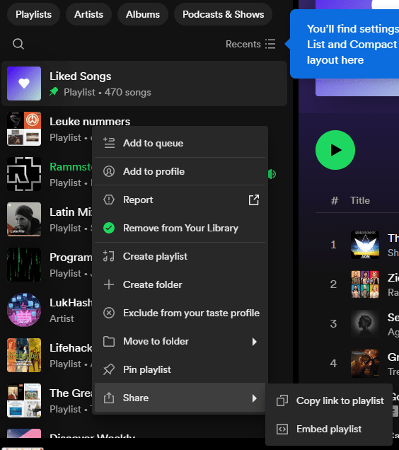
Get cover art from Logitech Media Server
http://192.168.1.3:9000/music/current/cover.jpg?player=<playerid>