A world map generator in php.
This php script selects randomly 3 cities from a CSV file and draws these on a worldmap.
No cities wil be choosen which have could cause a drawing overlap.
Every player can see the same generated worldmap with a countdown timer.
CSV example with places and coordinates (cities.csv)
London,905,412
Amsterdam,929,414
Wellington,1722,867
Costa Rica,524,640
New Delhi,1270,514
New York,567,477
Tokio,1548,500
generate.html
<html><body bgcolor=black>
<header>
  <div class="menu_area"></div>
  <center>
<p id="demo" style="text:white;"></p>
  </center>
</header>
<style>
html, body, header {
    overflow: hidden; /* Hide scrollbars */
    height: 100%;
    text: white;
}
header {
    background-image: url('world.php');
    background-size: cover;
}
  p {
  color: white;
  font-size: large;
  font-family: Verdana, Arial, sans-serif;
  font-size: 42px;
 }
</style>
<script>
	Date.prototype.addHours= function(h){
    this.setHours(this.getHours()+h);
    return this;
}

var countDownDate = new Date().addHours(1).getTime();
  var x = setInterval(function() {
  var now = new Date().getTime();
  var distance = countDownDate - now;
  var days = Math.floor(distance / (1000 * 60 * 60 * 24));
  var hours = Math.floor((distance % (1000 * 60 * 60 * 24)) / (1000 * 60 * 60));
  var minutes = Math.floor((distance % (1000 * 60 * 60)) / (1000 * 60));
  var seconds = Math.floor((distance % (1000 * 60)) / 1000);

  document.getElementById("demo").innerHTML = days + "d " + hours + "h "
  + minutes + "m " + seconds + "s ";

  if (distance < 0) {
    clearInterval(x);
    document.getElementById("demo").innerHTML = "EXPIRED";
  }
}, 1000);
</script>
</body></html>
Used world image to draw on.
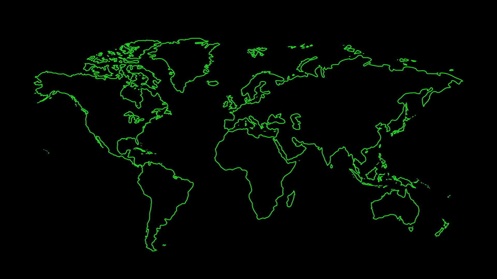
The squares and city names are dynamically drawn using php GD lib.
apt-get install apache2 php php-gd
php example:
// create image from source
$src = imagecreatefromjpeg('world.jpg');
$dest = imagecreatetruecolor(1920, 1080);
// 1920x1080
imagecopy($dest, $src, 0, 0, 0,0, 1920, 1080);
// assign color
$white = imagecolorallocate($dest, 255, 255, 255);
// rectangle example
imagerectangle($dest, $x, $y, $x2, $y2, $white);
// add text
Imagettftext($dest, 24, 0, $x, $y, $white, $font, "Text");
// set header output as image
header('Content-Type: image/jpg');
// output to browser
imagejpeg($dest);
// output to file
imagejpeg($dest, 'generatedworld.jpg');
// Free memory
imagedestroy($dest);
imagedestroy($src);
world.php is included as image, it dynamically generates the map
<?php

putenv('GDFONTPATH=' . realpath('.'));

// Name the font to be used (note the lack of the .ttf extension)
$font = 'tahoma.ttf';
$city1="";
$city2="";
$city3="";

// Create image instances
$src = imagecreatefromjpeg('world.jpg');
$dest = imagecreatetruecolor(1920, 1080);

// Copy
imagecopy($dest, $src, 0, 0, 0,0, 1920, 1080);

$green = imagecolorallocate($dest, 255, 255, 255);


$rows = file("cities.csv");
$len = count($rows);
$rand = [];
while (count($rand) < 1) {
    $r = rand(0, $len-1);
    if (!in_array($r, $rand)) {
        $rand[] = $r;
    }
}
foreach ($rand as $r) {
    $csv = $rows[$r];
    $data = str_getcsv($csv);
    $city1="$data[0]";
    $x1=$data[1];
    $y1=$data[2];
}

imagerectangle($dest, $x1-50, $y1-50, $x1+50, $y1+50, $green);
imagerectangle($dest, $x1-49, $y1-49, $x1+49, $y1+49, $green);
imagerectangle($dest, $x1-10, $y1, $x1+10, $y1-1, $green);
imagerectangle($dest, $x1, $y1-10, $x1-1, $y1+10, $green);
Imagettftext($dest, 24, 0, $x1-50, $y1-60, $green, $font, "$city1");

while($city2 == "") {

$rows = file("cities.csv");
$len = count($rows);
$rand = [];
while (count($rand) < 1) {
    $r = rand(0, $len-1);
    if (!in_array($r, $rand)) {
        $rand[] = $r;
    }
}
foreach ($rand as $r) {
    $csv = $rows[$r];
    $data = str_getcsv($csv);
    $x2=$data[1];
    $y2=$data[2];
    $deltax=abs($x2-$x1);
    $deltay=abs($y2-$y1);
}
if($data[0] != $city1 && $deltax > 100 && $deltay > 100 ){
	$city2=$data[0];
}

}


imagerectangle($dest, $x2-50, $y2-50, $x2+50, $y2+50, $green);
imagerectangle($dest, $x2-49, $y2-49, $x2+49, $y2+49, $green);
imagerectangle($dest, $x2-10, $y2, $x2+10, $y2-1, $green);
imagerectangle($dest, $x2, $y2-10, $x2-1, $y2+10, $green);
Imagettftext($dest, 24, 0, $x2-50, $y2-60, $green, $font, "$city2");


while($city3 == "") {

$rows = file("cities.csv");
$len = count($rows);
$rand = [];
while (count($rand) < 1) {
    $r = rand(0, $len-1);
    if (!in_array($r, $rand)) {
        $rand[] = $r;
    }
}
foreach ($rand as $r) {
    $csv = $rows[$r];
    $data = str_getcsv($csv);
    $x3=$data[1];
    $y3=$data[2];
    $deltax=abs($x3-$x1);
    $deltay=abs($y3-$y1);
    $deltax1=abs($x3-$x2);
    $deltay1=abs($y3-$y2);
}
if($data[0] != $city1 && $data[0] != $city2 && $deltax > 100 && $deltay > 100 && $deltax1 > 100 && $deltay1 > 100 ){
	$city3=$data[0];
}
}
imagerectangle($dest, $x3-50, $y3-50, $x3+50, $y3+50, $green);
imagerectangle($dest, $x3-49, $y3-49, $x3+49, $y3+49, $green);
imagerectangle($dest, $x3-10, $y3, $x3+10, $y3-1, $green);
imagerectangle($dest, $x3, $y3-10, $x3-1, $y3+10, $green);
Imagettftext($dest, 24, 0, $x3-50, $y3-60, $green, $font, "$city3");


// Output and free from memory
header('Content-Type: image/jpg');
imagejpeg($dest);
imagejpeg($dest, 'generatedworld.jpg');


imagedestroy($dest);
imagedestroy($src);
?>