Ben Eater Clock Module on steroids

Last Updated or created 2025-04-24

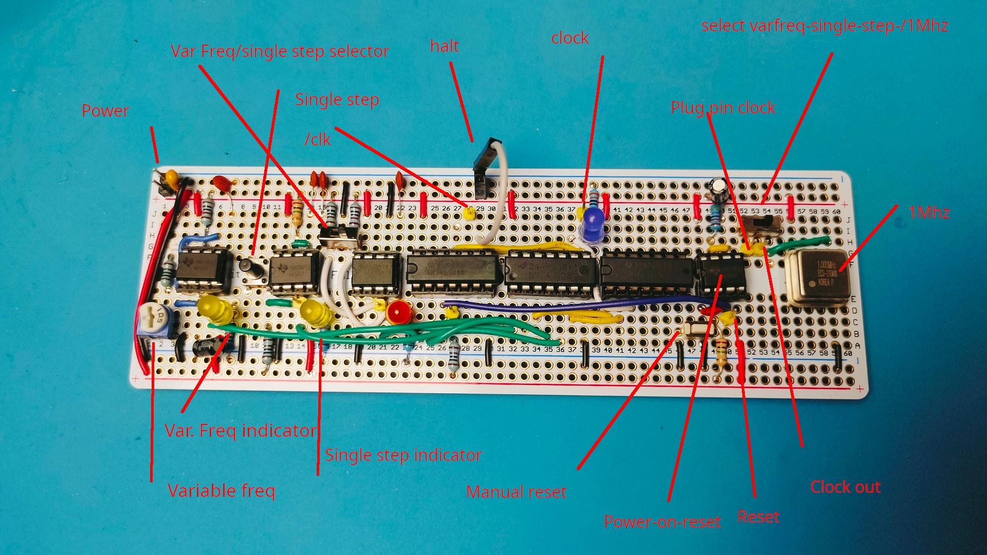
My previous build of the clock module is as Ben designed. Wellll . Not really, I added some components to change the clock range.

Okay, Ben’s design is awesome. Not because of its technical design. No, you will learn to use the NE555 chip in three ways!
Variable freq, debounce with delay and a flip-flop like switch
I added another function to it. While making my version.
I added a 555 power-on reset pulse part.

I used a perm board (which is shorter than a regular breadboard)
And I moved some components over and added some LEDs/pin headers.
While doing so, I only used 3/4 of the board.

So I added a power-on reset part with a manual push-button. (Partly like the C64 power-on)
I also added the 1Mhz crystal.

Rest of the boards will use JST connectors for the bus-connections.

I am working on big motor controllers and 3D print modelling for clients.
Busy .. work and play

Last Updated or created 2025-04-15

While working on my clients projects, I’ve been busy with other Fun stuff.

All will be posted more about soon

  • Designing 3D models for printing
  • Testing Arduino Code for RS485!
  • Creating T-shirt prints using 3D printing and bleach/paint with Vincent !
  • Transforming my Lab
  • Testing UM25C logging possibilities
  • Testing queries on overpass-turbo.eu (So much fun)
  • Playing chiptune music using Synthcart + Midi
  • Made V2 displayer on my 64×64 HUB75 led display
  • Bought a directional Wi-Fi antenna, tweaking wireshark to pinpoint rogue access points and clients.

Animatronics Tentacle Test

Last Updated or created 2025-04-15

Using 3x SG90s (metal gears).
These performed far better using my Servo tester than the cheap plastic ones.

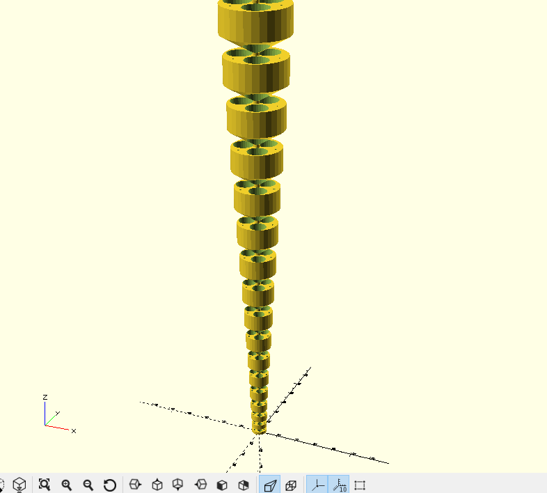
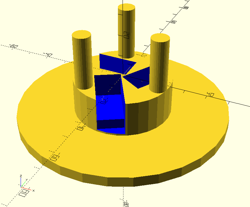
First version using Openscad, with variables to control how it looks.

This is printed using TPU.

RepeatingBit = 4;
nr = 20;
difference(){
union(){
for (a =[0:nr]) {
    translate([0,0,(a * (RepeatingBit))]) {
        translate([0,0,a*a*1.3])
        
        cylinder ( h=1+(a*1.1), r1=1,r2=7.5+(a*(a/10)), $fn=30 );
        translate([0,0,a*a*1.3+1+(a*1.1)])
        cylinder ( h=3+(a*1.5), r1=7.5+(a*(a/10)),r2=7.5+(a*(a/10)), $fn=30 );
        
        }
}
translate([0,0,0])
cylinder( h=650, r1=2,r2=4 , $fn=30 );
}

translate([5,0,-10])
rotate([0,2.5,0])
cylinder( h=1000, r1=1,r2=1 , $fn=30 );
translate([-3,4,-10])
rotate([-4/2,-3/2,0])
cylinder( h=1000, r1=1,r2=1 , $fn=30 );
translate([-3,-4,-10])
rotate([4/2,-3/2,0])
cylinder( h=1000, r1=1,r2=1 , $fn=30 );

translate([2,3,-10])
rotate([-1.4,0.6,0])
cylinder( h=1000, r1=2,r2=nr*1.3 , $fn=30 );

translate([2,-3,-10])
rotate([1.6,0.7,0])
cylinder( h=1000, r1=2,r2=nr*1.3 , $fn=30 );

translate([-3.5,0,-10])
rotate([0,-1.8,0])
cylinder( h=1000, r1=2,r2=nr*1.3 , $fn=30 );

}

Video with some organic movement

Using a Raspberry Pi, Python3 and a Servo HAT.

Bottom part

Logic Analyser (part 2)

Last Updated or created 2025-04-15

So I got the PCBs.

Contact me if you want to have one.

Testing Cmos and TTL levels!

Working perfectly!

Improvements to be made:

  • OE (Output enable per 8 bits instead of one generic)
  • Design a case!

Below some screenshots. TTL and I2C cmos with decoding.