Above a screenshot of a browser screen (Left and Right in fullscreen)
Colors are a little of (codec Red/Blue problem?)
But the setup works!
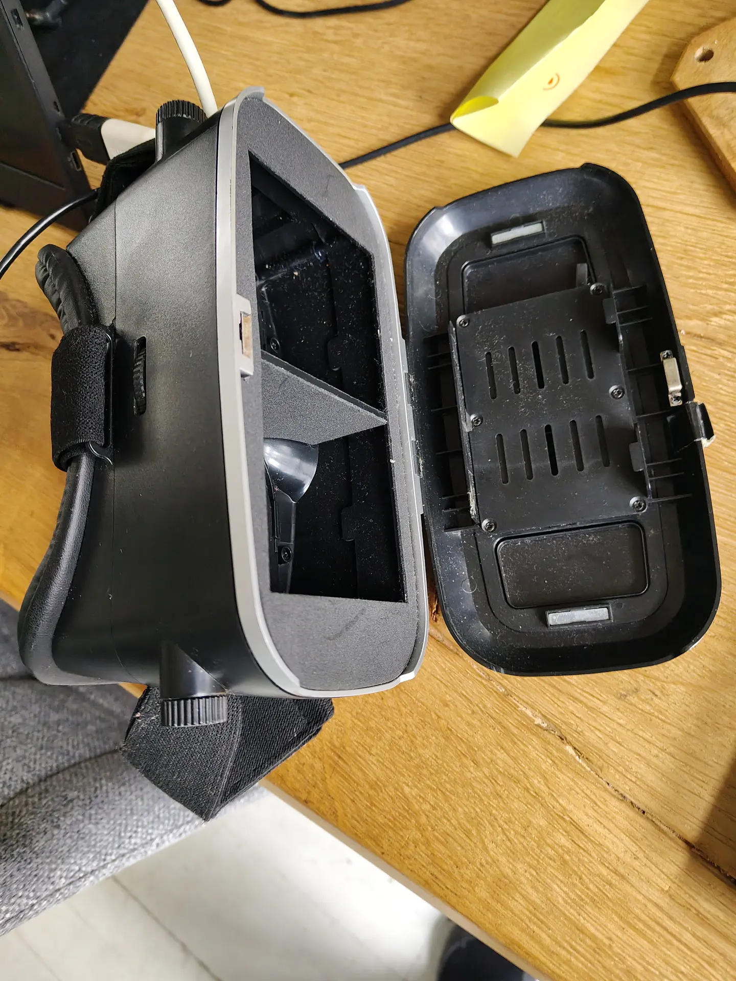
I used a android phone in above setup.
I tried a Quest 2 VR set, but I couldn’t get the browser in full screen mode. (YET)
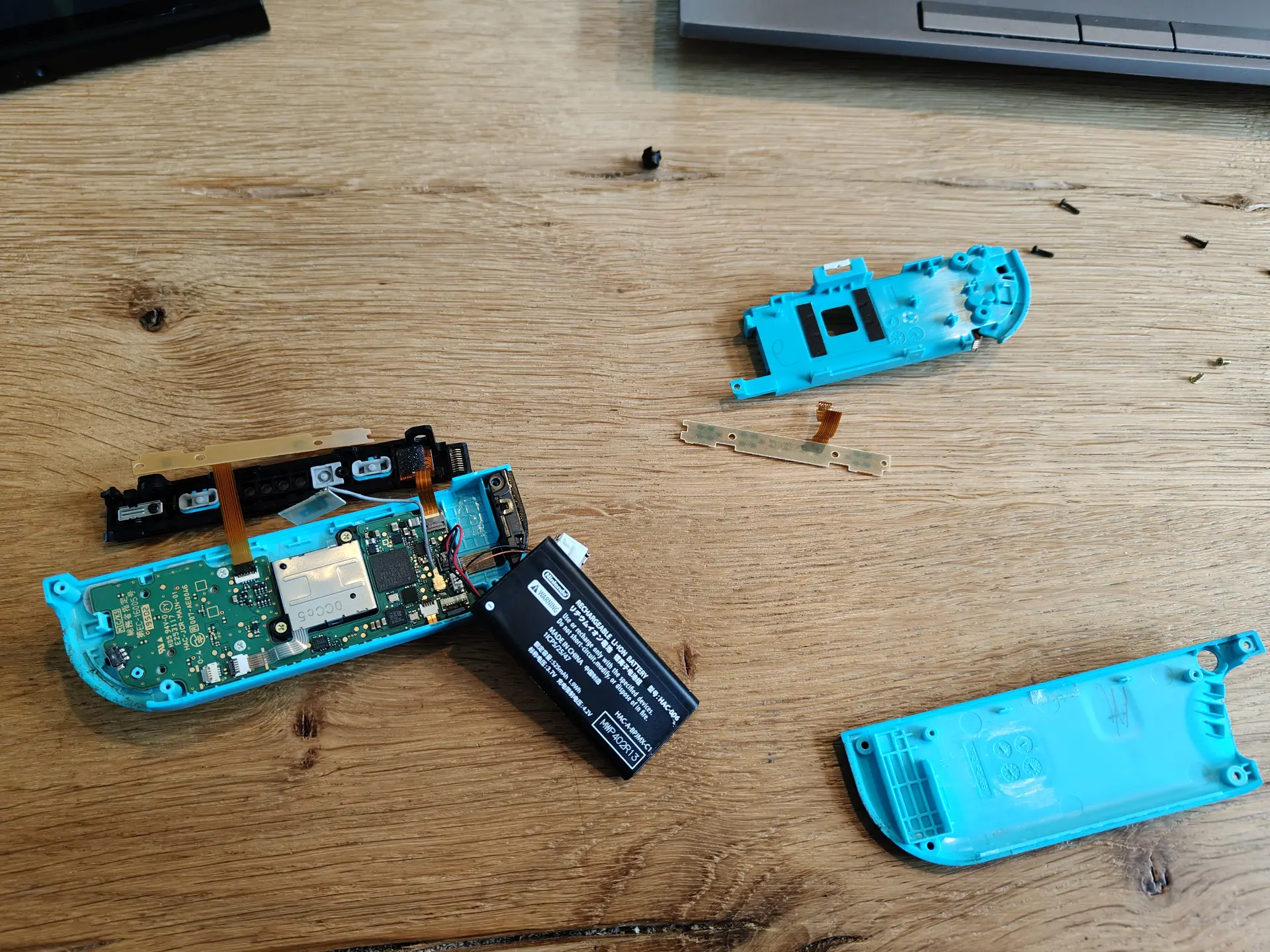
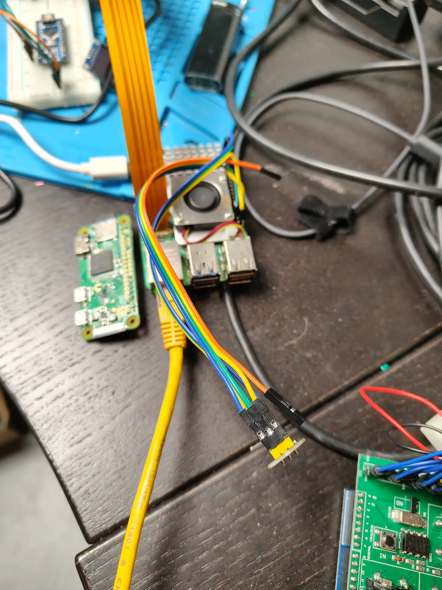
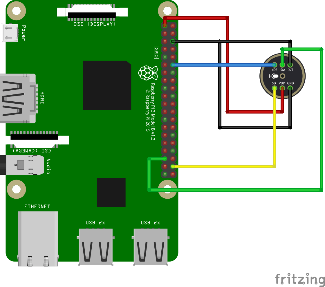
Hardware setup
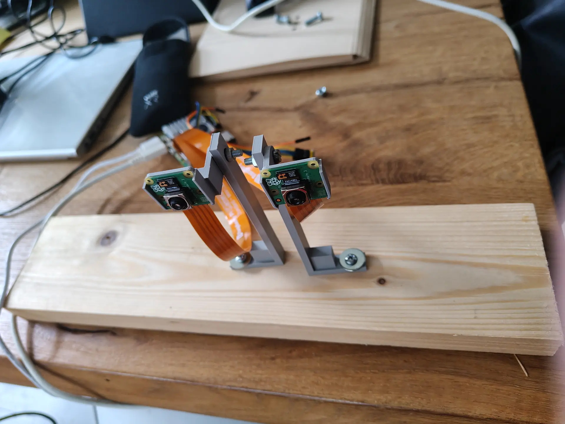
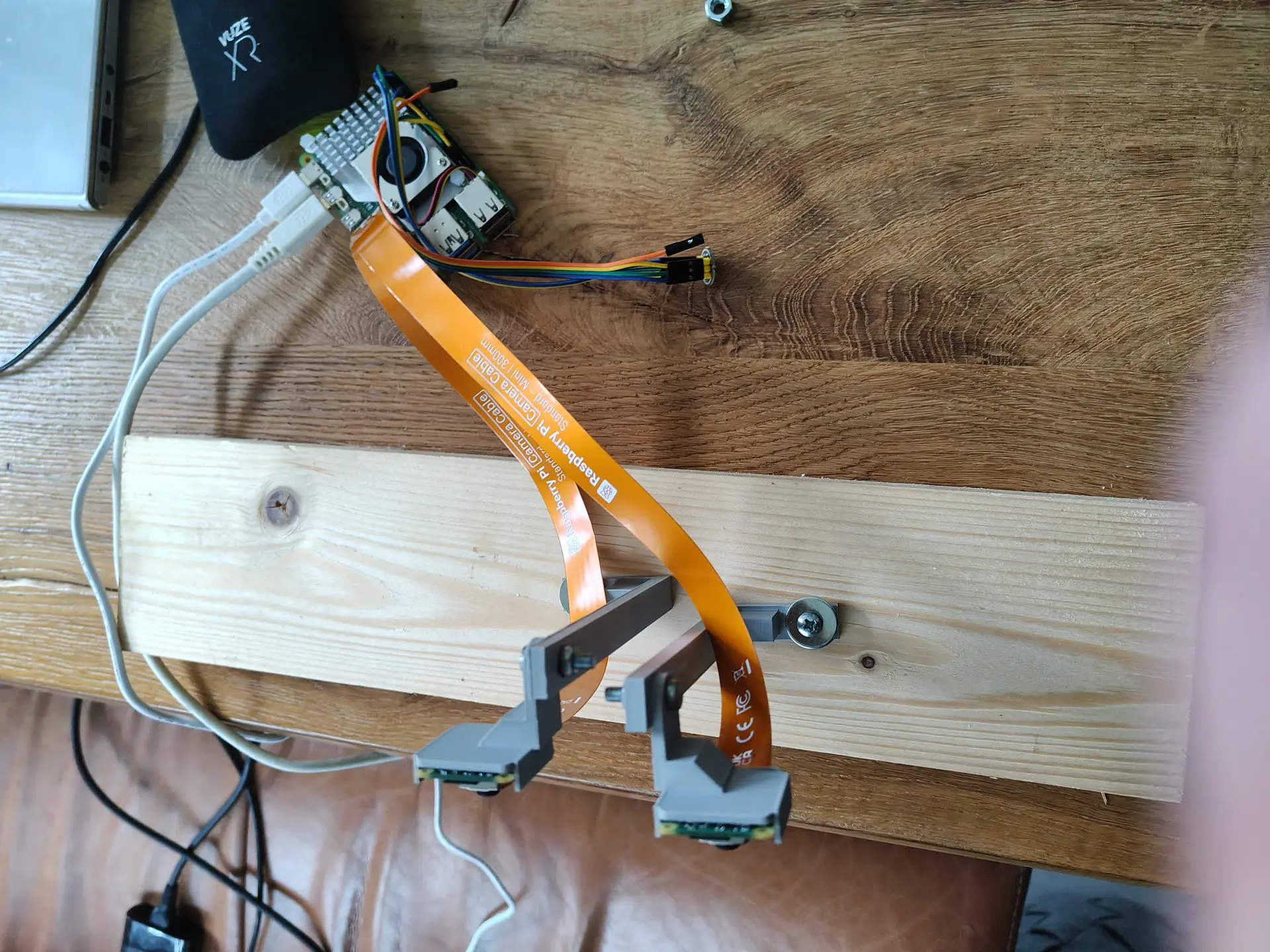
Two Raspberry Pi Camera Modules, connected via the two 4lane-MIPI DSI/CSI connectors.
Manually focussed and using some 3D printed stands on a piece of wood will do for now.
I build a RTSP NGinx proxy to test, which I previously used for OBS. But there was too much latency.
So I used below webrtc setup, with a latency below 80ms.
(I previously did some test using Janus)
CODE:
wget https://github.com/bluenviron/mediamtx/releases/download/v1.16.1/mediamtx_v1.16.1_linux_arm64.tar.gz
tar xzvf media*
cp mediamtx.yml mediamtx.org
NEW mediamtx.yml
webrtc: yes
webrtcAddress: :8889

rtmp: yes
rtmpAddress: :1935

paths:
  dualcam:
    source: publisher
run it
./mediamtx mediamtx.yml
Next make a streamer.
This Python script takes two square camera inputs, merge them side-by-side to one image and pushed the H264 frame to MediaMTX
import numpy as np
from picamera2 import Picamera2
import subprocess
import time

#WIDTH = 1280
WIDTH = 720
HEIGHT = 720
FPS = 30
BITRATE = "2500k"
RTMP_URL = "rtmp://127.0.0.1:1935/dualcam"  # MediaMTX RTMP

# FFmpeg  raw frames / H.264
ffmpeg_cmd = [
    "ffmpeg",
    "-y",
    "-f", "rawvideo",
    "-pix_fmt", "bgr24",
    "-s", f"{WIDTH*2}x{HEIGHT}",
    "-r", str(FPS),
    "-i", "-",
    "-c:v", "libx264",
    "-preset", "ultrafast",
    "-tune", "zerolatency",
    "-b:v", BITRATE,
    "-g", str(FPS),  # keyframe every second
    "-x264-params", "keyint=30:min-keyint=30:no-scenecut=1",
    "-pix_fmt", "yuv420p",
    "-f", "flv",
    RTMP_URL
]


ffmpeg = subprocess.Popen(ffmpeg_cmd, stdin=subprocess.PIPE, bufsize=0)

picam0 = Picamera2(0)
picam1 = Picamera2(1)

cfg0 = picam0.create_video_configuration(
    main={"size": (WIDTH, HEIGHT), "format": "BGR888"}, controls={"FrameRate": FPS}
)
cfg1 = picam1.create_video_configuration(
    main={"size": (WIDTH, HEIGHT), "format": "BGR888"}, controls={"FrameRate": FPS}
)

picam0.configure(cfg0)
picam1.configure(cfg1)

picam0.start()
picam1.start()

print("Streaming to MediaMTX via RTMP...")

try:
    while True:
        f0 = picam1.capture_array()
        f1 = picam0.capture_array()
        combined = np.hstack((f0, f1))
        ffmpeg.stdin.write(combined.tobytes())
        time.sleep(1/FPS)
except KeyboardInterrupt:
    print("Stopping...")
finally:
    picam0.stop()
    picam1.stop()
    ffmpeg.stdin.close()
    ffmpeg.wait()
Open using http://REMOTEIP:8889/dualcam