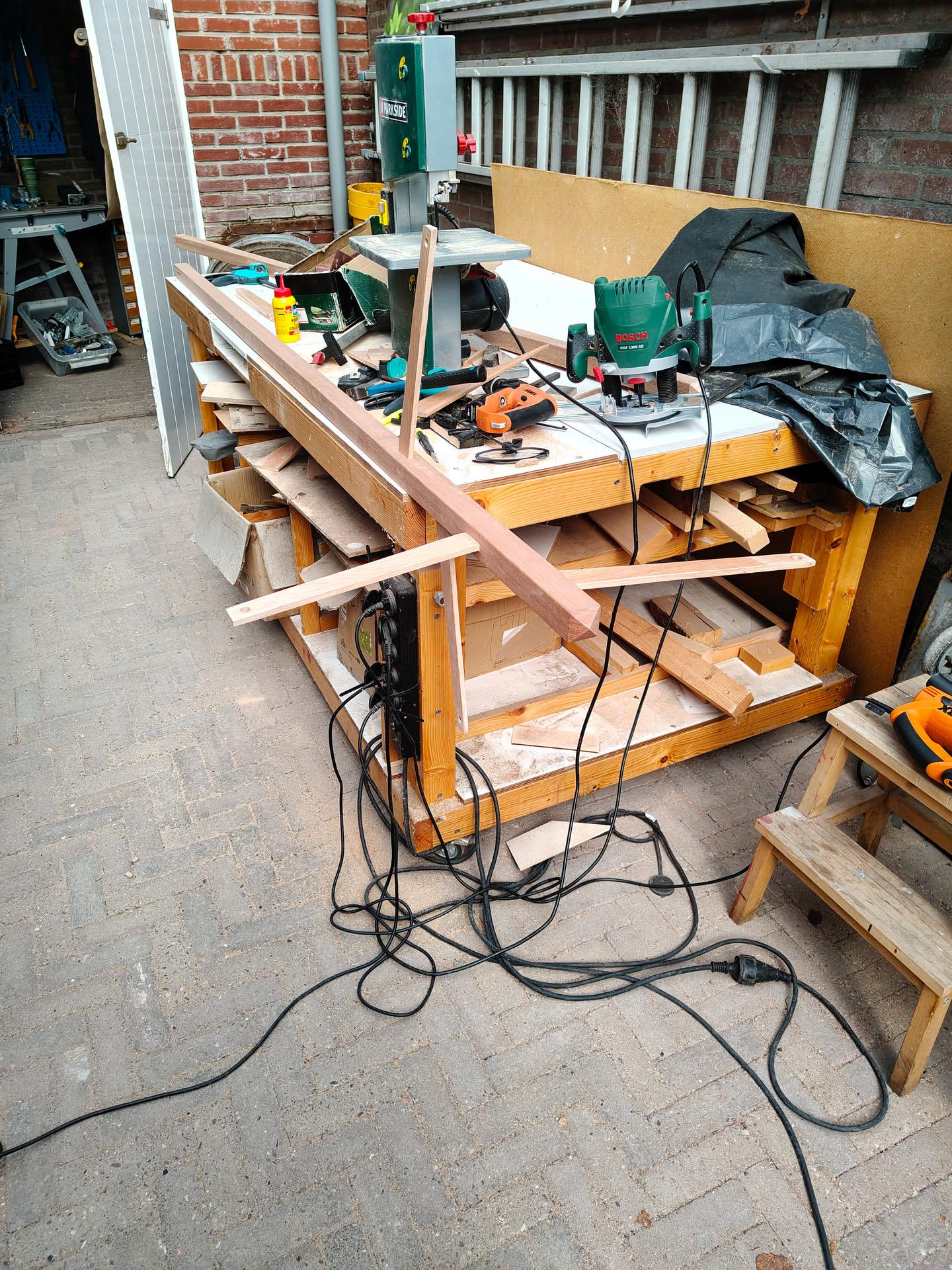
Now, I’ve made a board with 16 modified buttons and some micropython code.
White = mole, green = hit in time, red = wrong button/out of time, rainbow = bonus points.
Now i have to think of a display and select buttons, to select the game mode and see the score.
Schematic
Above is a simplified schematic. See notes below.
Led rings are 8 not in example 12 (didn’t have that part in fritzing)
Led rings have 5V, GND, DI (data in) and DO (data out)
Led rings are connected in series, python code divides by 8
GPIO for buttons (16 yellow) have internal PICO pullup resistors
Todo: Screen and mode select
Game modes : Currently I can think of four.
1 Player mode – with bonus button – works kindda
2 Player mode – Green player 1 and Blue player 2 – need testing
2 Player mode (half playfield) … todo
Above with mixed random colors, press only GREEN (or blue) .. todo
1 Player mode – all random colors + bonus .. todo
1 Player mode – with bonus button – keep bonus pressed for 5 seconds to double, so you need to single hand press others. (Missing is reset bonus?!?) … todo
Button keeps lit until pressed .. do 10 in a row. Print fastest and average time… todo
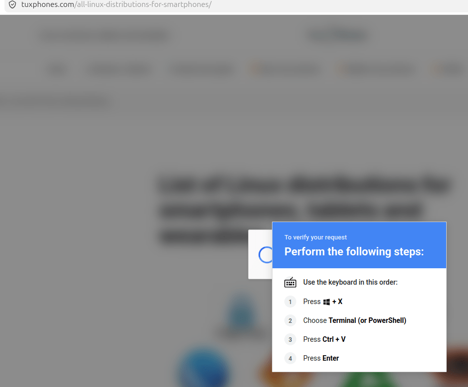
This is highly suspicious and matches a classic malware stager/downloader:
Uses XOR string obfuscation.
Hides its command-and-control URL.
Downloads code from the Internet.
Decrypts the downloaded content.
Executes it via Invoke-Expression.
Leaves the real payload invisible until runtime.
Without retrieving the content from the remote server, nobody can say exactly what the final payload does, but the code you’ve shown is unquestionably acting as a loader/stager whose job is to fetch and run additional code from a remote host. I would treat it as malicious unless proven otherwise.
Next I tried to download the payload mentioned in step 5. But the domain was not resolvable and not in archive.org wayback machine.
Maybe ChatGPT got it wrong and it was http://confitalia.it/ This one had a strange history, but no downloadable exploit any more .. case closed
I wanted to migrate the last documents I have in google drive to my own netcloud instance with wordproccessing.
I the past I tried Collabora.
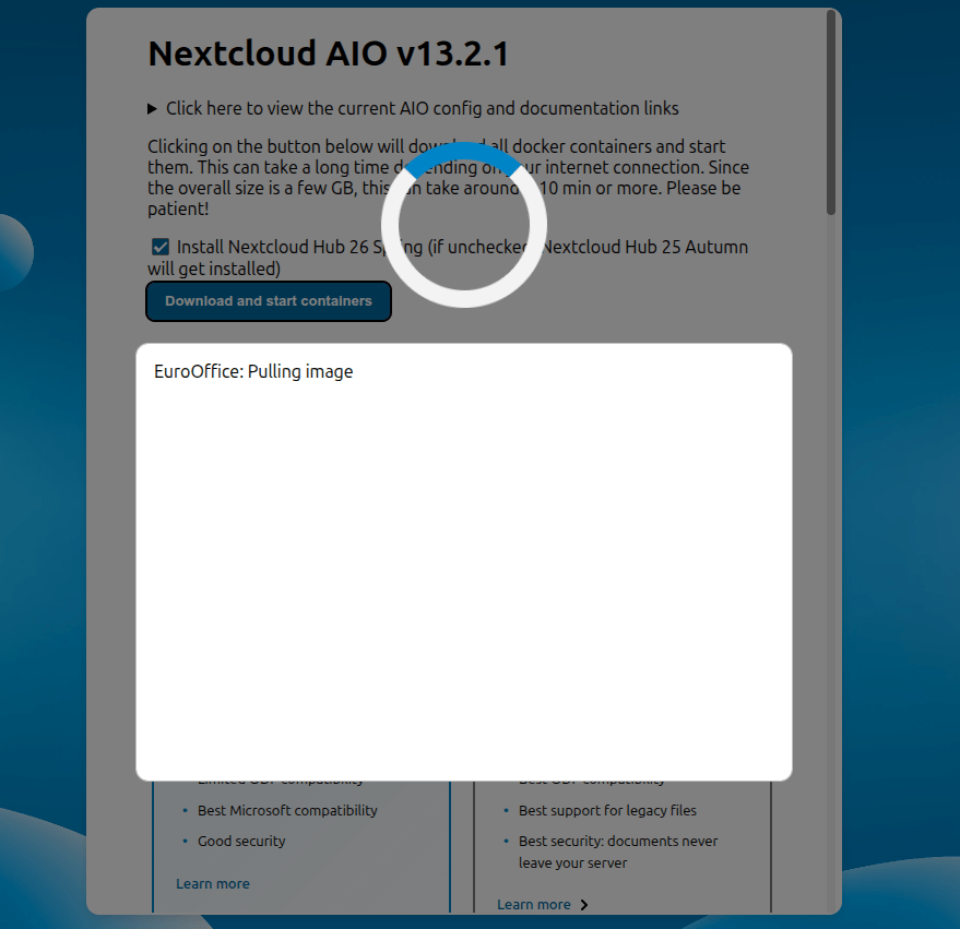
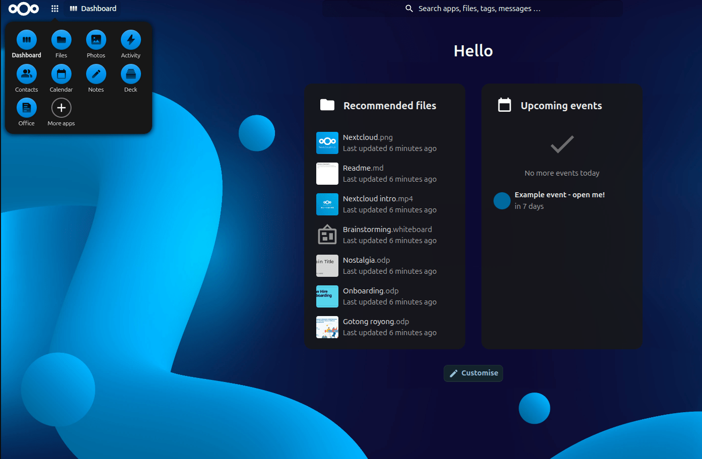
But today Nextcloud Hub 26 came out. WITH euro office!
Euro-Office is a FOSS office suite and collaborative software platform based on OnlyOffice that provides editors for documents, spreadsheets, presentations, and PDFs. The software includes web-based, desktop, and mobile applications designed for document creation, editing, and collaborative work
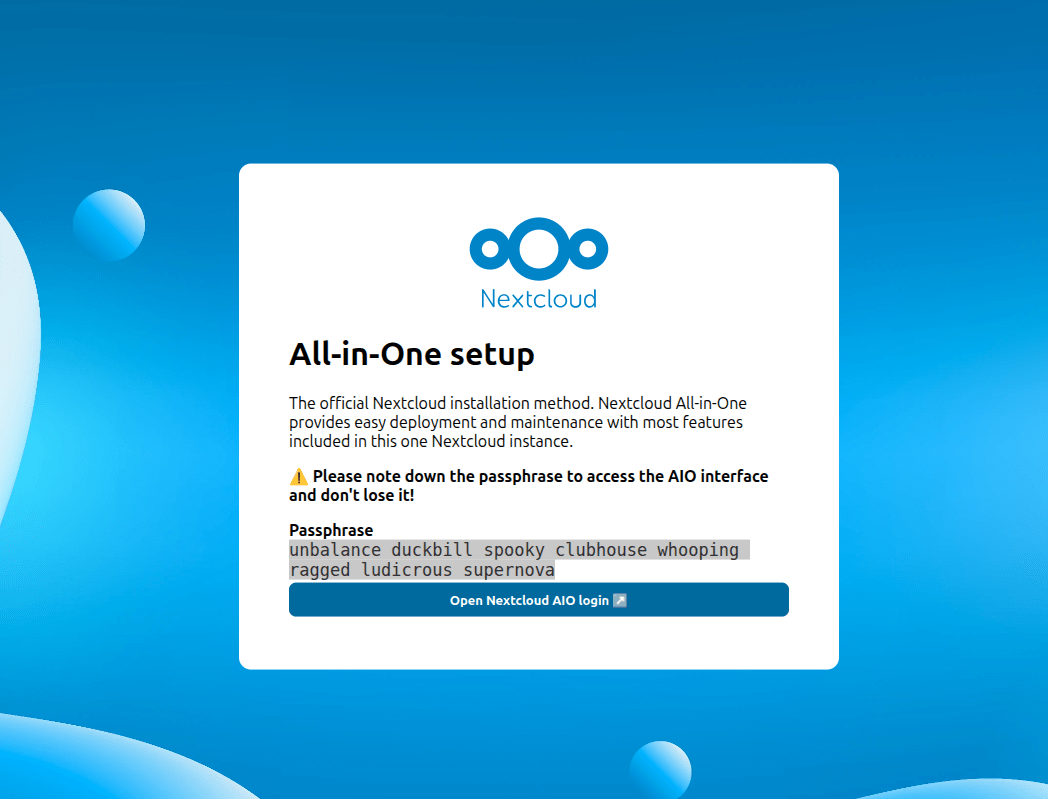
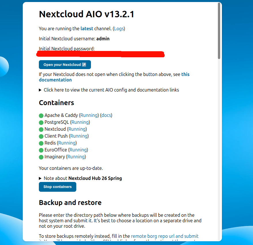
I installed Nextcloud AIO (all in one), using docker. Easy peasy.
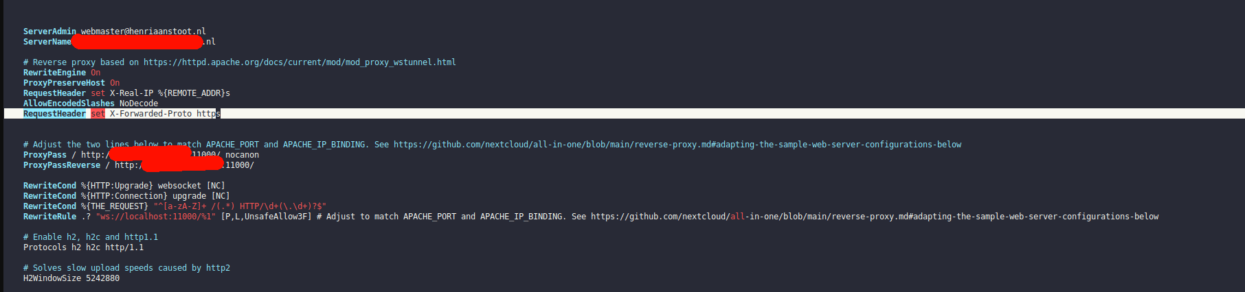
Even the configuration for reverse proxies are well documented. And almost perfect (more on this futher down this post)
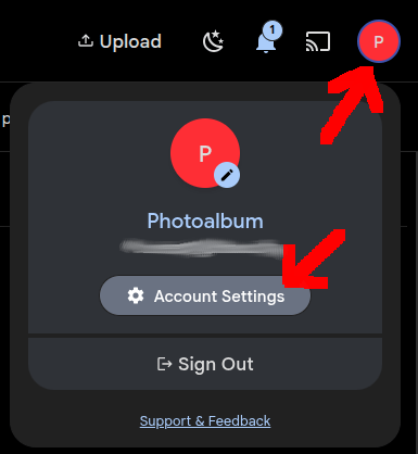
NOT MY CREDENTIALS, BUT A TEST INSTALL
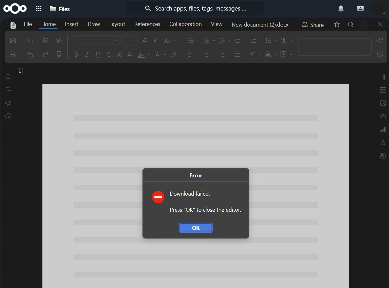
I tried to open an office document, but it gave me an error.
I’ve seen this mentioned online in forums. (The software is very new, and not well tested yet) But I found the sollution to this issue. I needed to change the configuration of my apache reverse proxy.
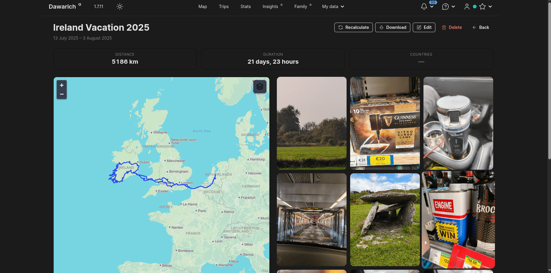
When ingesting WhatsApp media, the dates in the database will contain the ingest date. This is because the GPS/Date and other exif information are removed from the Media in WhatsApp.
NOTES:
Always import your camera media first, these will contain all exif info, if you upload WhatsApp media containing the same image it can be skipped. (Look for deduplication tip below)
WhatsApp autouploaded using the App on your phone rarely needs adjusting. (Taking a photo and uploading it the same day will fix the wrong day issue)
Luckily the WhatsApp media contains the date in the filename.
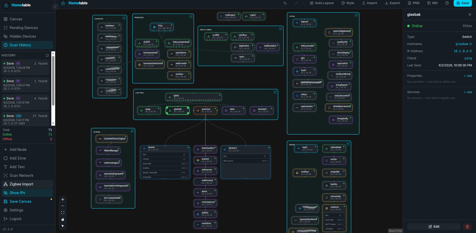
This software will connect to your immich instance, searches for ingestdates and whatsapp filenames discrepancies. And wil fix these in the immich database.
I’ve got a directory containing above code for every user, with their own .env file, and custom filters
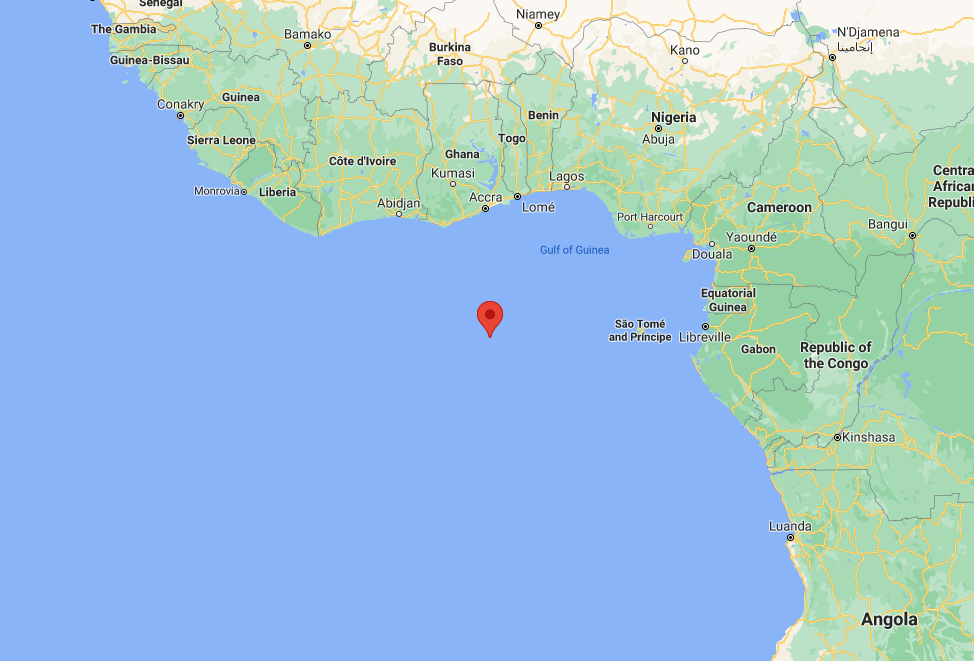
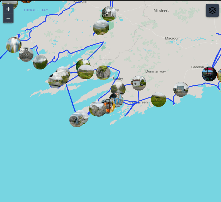
Sometimes media has a incorrect GPS location, or it is missing, or as above set as 0:0
You CAN change the location of Images using the MAP in Immich. (Select MAP > Day or image > Menu: Change location) (Also under Utilities) Immich WILL NOT change your image!, It will write a sidecar file with updated location info.
How I like to fix this: Download the images for which you want to remove the GPS information. Delete from Immich. Run below script over those images to remove Exif information and reupload.
exiftool -gps:all= FILENAME
Loads of the same images
Deduplicate? : Use Utilities > Review duplicates
Select camera instead of WhatsApp image to keep. (Most of the time bigger and has all exif information!)
Burst photos or simular photos? Use Stacking. This will show only ONE thumbnail in albums/timeline.
Manage people data in bulk : Options to update people data in bulk, and with advance filters
People Merge Suggestion : Option to bulk merge people with suggested faces based on similarity.
Update Missing Locations : Find assets in your library those are without location and update them with the location of the asset.
Potential Albums : Find albums that are potential to be created based on the assets and people in your library.
Analytics : Get analytics on your library like assets over time, exif data, etc.
Smart Search : Search your library with natural language, supports queries like “show me all my photos from 2024 of “
Bulk Date Offset : Offset the date of selected assets by a given amount of time. Majorly used to fix the date of assets that are out of sync with the actual date.
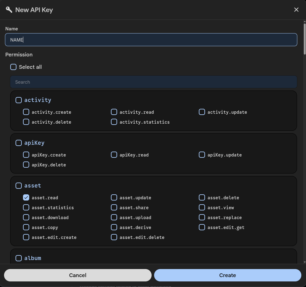
PYTHON script to download an album (with a filename filter)
NOTE: At the bottom you can remove the # comments to also REMOVE from immich
import requests
import os

IMMICH_URL = "http://192.168.1.2:2283/api"
API_KEY = "2Nk4sO4eEm001Cm1Dsnl3XXXXXXXXXXXXXXX"

ALBUM_ID = "c4ce0661-0c4c-4c49-b6c1-XXXXXXXXXXXXXXXXXXXXX"
FILENAME_PREFIX = "VID_"  # filename filter

HEADERS = {
    "x-api-key": API_KEY
}

DOWNLOAD_DIR = "./downloaded"
os.makedirs(DOWNLOAD_DIR, exist_ok=True)


def get_album_assets(album_id):
    r = requests.get(
        f"{IMMICH_URL}/albums/{album_id}",
        headers=HEADERS
    )
    r.raise_for_status()
    return r.json()["assets"]


def filter_assets(assets):
    # simulate SQL LIKE 'IMG_2023%'
    return [
        a for a in assets
        if a["originalFileName"].startswith(FILENAME_PREFIX)
    ]


def download_asset(asset):
    asset_id = asset["id"]
    filename = asset["originalFileName"]

    url = f"{IMMICH_URL}/assets/{asset_id}/original"

    r = requests.get(url, headers=HEADERS, stream=True)
    r.raise_for_status()

    path = os.path.join(DOWNLOAD_DIR, filename)

    with open(path, "wb") as f:
        for chunk in r.iter_content(8192):
            f.write(chunk)

    return path


def delete_assets(asset_ids):
    r = requests.delete(
        f"{IMMICH_URL}/assets",
        headers=HEADERS,
        json={"ids": asset_ids}
    )
    r.raise_for_status()


def main():
    print("Fetching album assets...")
    assets = get_album_assets(ALBUM_ID)

    print(f"Total assets in album: {len(assets)}")

    print("Filtering by filename...")
    filtered = filter_assets(assets)

    print(f"Matched assets: {len(filtered)}")

    downloaded = []

    print("Downloading...")
    for asset in filtered:
        try:
            path = download_asset(asset)
            downloaded.append((asset["id"], path))
        except Exception as e:
            print(f"Download failed: {asset['id']} - {e}")

    # VERIFY
    print("Verifying...")
    if len(downloaded) != len(filtered):
        print("Download mismatch. Abort delete.")
        return

    for _, path in downloaded:
        if not os.path.exists(path) or os.path.getsize(path) == 0:
            print(f"Invalid file: {path}")
            return

    print("Verification OK")

    # DELETE
    ids_to_delete = [asset_id for asset_id, _ in downloaded]

    #print("Deleting assets...")
    #delete_assets(ids_to_delete)

    print("Done!")


if __name__ == "__main__":
    main()
find -type f -iname '*.desc' -exec rm  {} \;


for f in =X*; do
    new=$(echo "$f" | sed -E 's/^=X//; s/X=(\.[0-9]+)?$/\1/')
    mv -- "$f" "$new"
done

for f in *.[0-9]*; do
    base=${f%.[0-9]*}

    if [ -f "$base" ] && cmp -s -- "$base" "$f"; then
        echo "Removing duplicate: $f"
        rm -- "$f"
    fi
done

for f in *.[0-9]*; do
    n=${f##*.}          # 1, 2, 3 ...
    base=${f%.*}        # winmail.dat
    ext=${base##*.}     # dat
    name=${base%.*}     # winmail

    mv -- "$f" "${name}-${n}.${ext}"
done

for f in -*; do
    new="${f#-}"
    mv -- "$f" "$new"
done

for f in -*; do
    new="${f#-}"
    mv -- "$f" "$new"
done

for f in *X; do
    mv -- "$f" "${f%X}"
done


mkdir -p pdf images audio text movies bww zip midi html vcf xml
mv *PDF pdf
mv *pdf pdf
mv *gif images
mv *GIF images
mv *jpg images
mv *bmp images
mv *BMP images
mv *jpeg images
mv *JPG images
mv *Jpg images
mv *png images
mv *tif images
mv *eps images
mv *PNG images
mv *Png images
mv *svg images
mv *psd images
mv *mp3 audio
mv *MP3 audio
mv *wma audio
mv *wav audio
mv *m4a audio
mv *txt text
mv *wri text
mv *doc text
mv *docx text
mv *xls text
mv *XLS text
mv *ppt text
mv *pptx text
mv *xlsx text
mv *mp4 movies
mv *MP4 movies
mv *avi movies
mv *mov movies
mv *MOV movies
mv *mpg movies
mv *MPG movies
mv *bww bww
mv *abc bww
mv *pio bww
mv *zip zip
mv *ZIP zip
mv *tgz zip
mv *tar zip
mv *rar zip
mv *mid midi
mv *html html
mv *htm html
mv *vcf vcf
mv *xml xml