Last Updated or created 2022-08-01
Started with a new Micro computer project.
Update: 20220721 .. VIA chip installed
Update: 20220801 .. changed layout, addressing and added rom, see below post.
Such a influencial little processor … Apple, Vic-20, C64 (with modifications), PET, BBC Micro, Oric, Atari and Nintendo.
Another (big brother) influencial CPU is the 68000.
(Amiga/Atari ST/ Macintosh/Sinclair)
I’ve made a 680x computer in the past, and i want to make another one.
This one will be based on a 6502, because i used to program on this cpu when i got my Vic-20.
Goals of this project:
- 6502 Cpu
- Memory and Rom
- Rom must contain a good machinecode monitor
- Adjustable clock
- Now using Ben Eatons clock diagram, but i will move this to a programmable arduino, with a display which shows the clock rate
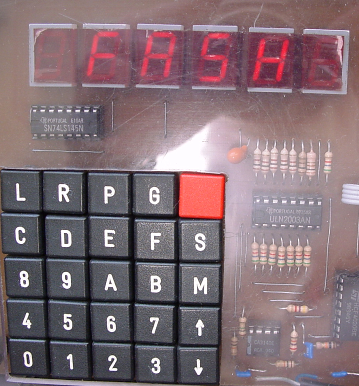
- Hex keyboard ro program the machine, just like picture below
- Display which was a resolution of at least 640×480
- It will be a slow screen, character printing and a gfx mode?
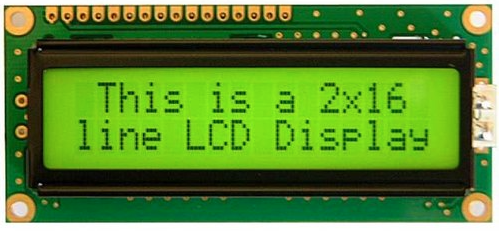
- First probably a SPLC780 HD44780, so i can enter/edit machine code.
- Hopefully using a SID chip
- Hardware monitoring of the address and data lines like movie below
- Programming via serial/usb, by halting the 6502 cpu and pushing data into memory or fake-eprom with a arduino
- Save/restore by modifying memory
- Small
Update 20220721
Via chip is on the board.
For now i’m using a old display, like this one
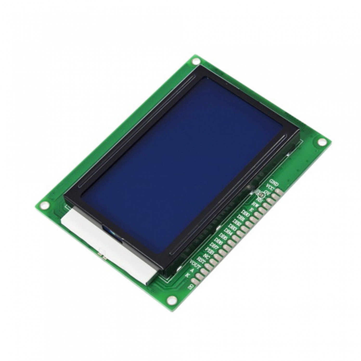
I was planning to use this one
I will reuse the schematics i’ve used for the 680x computer. (Posted above)
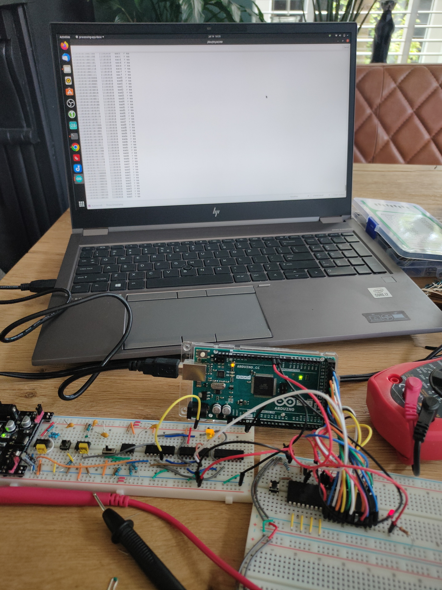
Update: 20220801
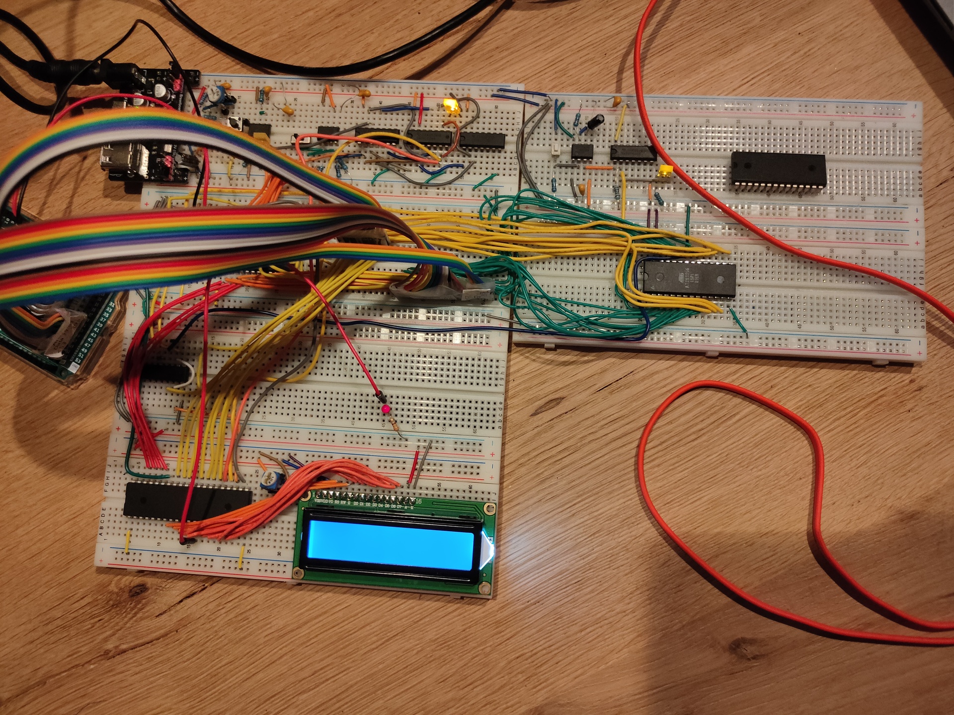
Added ROM, and changed layout.
Every breadboard has a function now.
Upper left, Ben’s Clock module (this is going to be changed to a arduino with display which shows frequency)
Upper right, power-on reset (Reused part of C64 schematic)
Second row left, the 6502
On the right the ROM, RAM i also going to install here.
3rd Row, Address decoding, this is going to be a dynamic setup using dip switches and a eeprom for decoding (i know, this kind of decoding is slow, but i don’t need speed), on the right probably the hex keyboard with its own 6522.
4rd row left, a temporary display 16X2 connected via a 6522. Here i want to have a graphical display.
4rd row right (not started this part yet) a sound device. SID or a Yamaha sound chip i still have.