Last Updated or created 2023-01-12
Way back in 2018 i was playing around with i2c and touch.
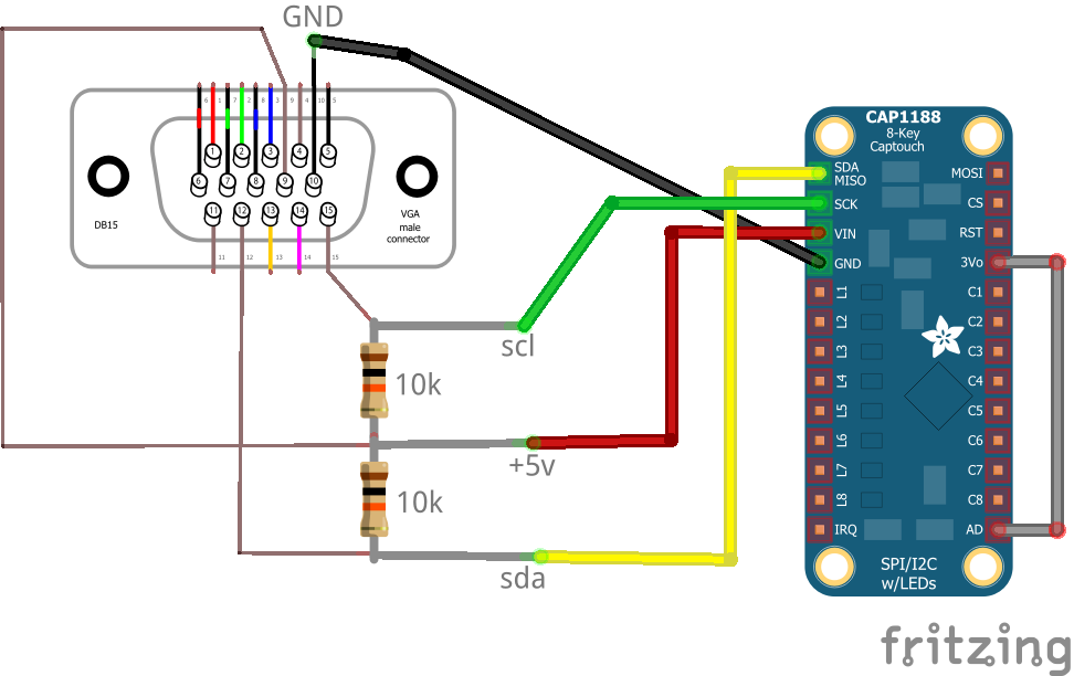
I remembered that VGA was using i2c to get information from monitors like brand/type and connection information.
I managed to access the cap1188 up to my Laptop via VGA.
The final python code i used to play with the variables and playing sound i can’t find.
But below is the test code
#!/usr/bin/python

# NOTE: i did a address scan, now i have 3v3 connected to AD, so probably the address is 0x28 !!

import smbus

bus = smbus.SMBus(1)    # 0 = /dev/i2c-0 (port I2C0), 1 = /dev/i2c-1 (port I2C1)

DEVICE_ADDRESS = 0x29
DEVICEx = 0x10
DEVICE_REG_MODE1 = 0x00
DEVICE_REG_LEDOUT0 = 0x1d

#Write a single register
bus.write_byte_data(DEVICE_ADDRESS, 0x1f, 0x3F)

#Write an array of registers
#ledout_values = [0xff, 0xff, 0xff, 0xff, 0xff, 0xff]
#bus.write_i2c_block_data(DEVICE_ADDRESS, DEVICE_REG_LEDOUT0, ledout_values)
while True:

        print bus.read_byte_data(DEVICE_ADDRESS,0x10), bus.read_byte_data(DEVICE_ADDRESS,0x11) , bus.read_byte_data(DEVICE_ADDRESS,0x12), bus.read_byte_data(DEVICE_ADDRESS,0x13), bus.read_byte_data(DEVICE_ADDRESS,0x14), bus.read_byte_dat
a(DEVICE_ADDRESS,0x15), bus.read_byte_data(DEVICE_ADDRESS,0x16), bus.read_byte_data(DEVICE_ADDRESS,0x17)
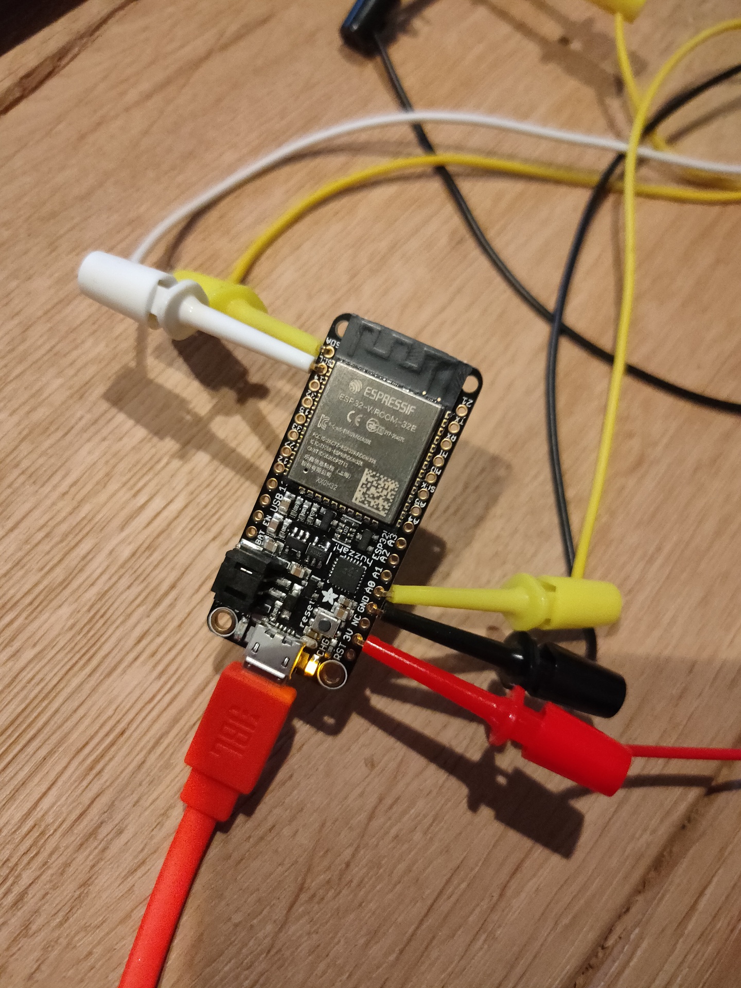
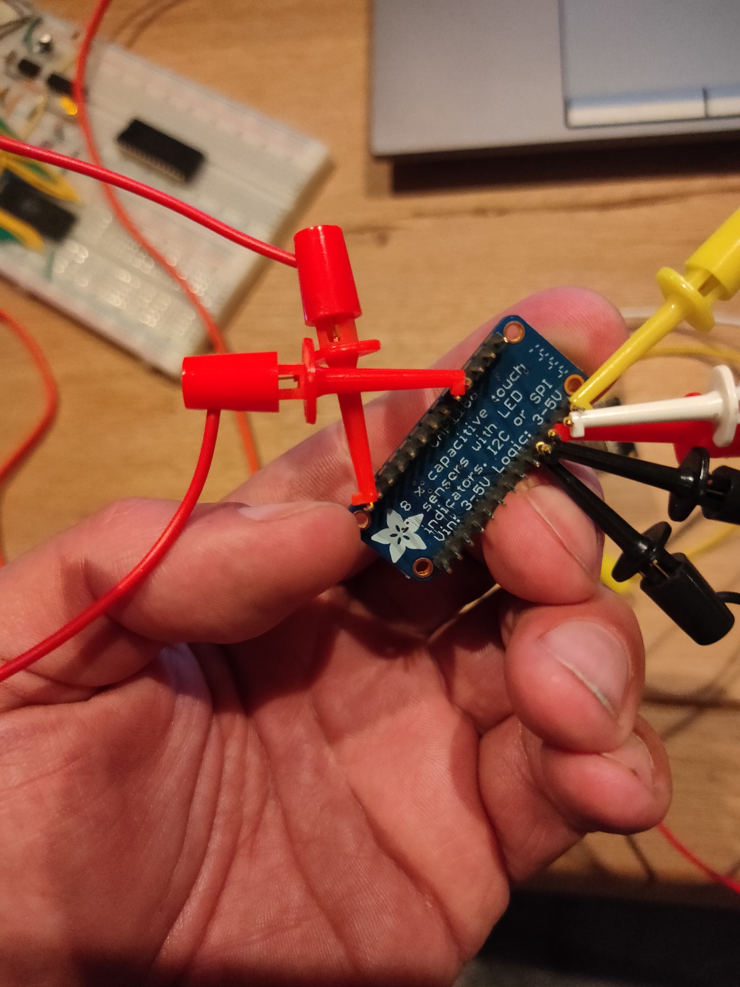
Today i connected the cap1188 to a ESP32 and a piezo buzzer.
/*** Based on below library ***/
/*** Changed pins and added sound ***/

/***************************************************
  This is a library for the CAP1188 I2C/SPI 8-chan Capacitive Sensor

  Designed specifically to work with the CAP1188 sensor from Adafruit
  ----> https://www.adafruit.com/products/1602

  These sensors use I2C/SPI to communicate, 2+ pins are required to
  interface
  Adafruit invests time and resources providing this open source code,
  please support Adafruit and open-source hardware by purchasing
  products from Adafruit!

  Written by Limor Fried/Ladyada for Adafruit Industries.
  BSD license, all text above must be included in any redistribution
 ****************************************************/

#include <Wire.h>
#include <SPI.h>
#include <Adafruit_CAP1188.h>

const int TONE_OUTPUT_PIN = 26;
const int TONE_PWM_CHANNEL = 0;
int freq = 0;


// Reset Pin is used for I2C or SPI
#define CAP1188_RESET  9

// CS pin is used for software or hardware SPI
#define CAP1188_CS  10

// These are defined for software SPI, for hardware SPI, check your
// board's SPI pins in the Arduino documentation
#define CAP1188_MOSI  11
#define CAP1188_MISO  12
#define CAP1188_CLK  13

// For I2C, connect SDA to your Arduino's SDA pin, SCL to SCL pin
// On UNO/Duemilanove/etc, SDA == Analog 4, SCL == Analog 5
// On Leonardo/Micro, SDA == Digital 2, SCL == Digital 3
// On Mega/ADK/Due, SDA == Digital 20, SCL == Digital 21

// Use I2C, no reset pin!
Adafruit_CAP1188 cap = Adafruit_CAP1188();

// Or...Use I2C, with reset pin
//Adafruit_CAP1188 cap = Adafruit_CAP1188(CAP1188_RESET);

// Or... Hardware SPI, CS pin & reset pin
// Adafruit_CAP1188 cap = Adafruit_CAP1188(CAP1188_CS, CAP1188_RESET);

// Or.. Software SPI: clock, miso, mosi, cs, reset
//Adafruit_CAP1188 cap = Adafruit_CAP1188(CAP1188_CLK, CAP1188_MISO, CAP1188_MOSI, CAP1188_CS, CAP1188_RESET);

void setup() {
  Serial.begin(9600);
  Serial.println("CAP1188 test!");
  ledcAttachPin(TONE_OUTPUT_PIN, TONE_PWM_CHANNEL);


  // Initialize the sensor, if using i2c you can pass in the i2c address
  if (!cap.begin(0x28)){
  //if (!cap.begin()) {
    Serial.println("CAP1188 not found");
    while (1);
  }
  Serial.println("CAP1188 found!");
}

void loop() {
  uint8_t touched = cap.touched();

  if (touched == 0) {
    // No touch detected
    return;
  }

  for (uint8_t i=0; i<8; i++) {
    if (touched & (1 << i)) {
      Serial.print(touched); Serial.print("\t");
      freq = (i * 100);
      ledcWriteTone(TONE_PWM_CHANNEL, freq);
      delay(100);
    }
  }

  Serial.println();
  delay(50);
}
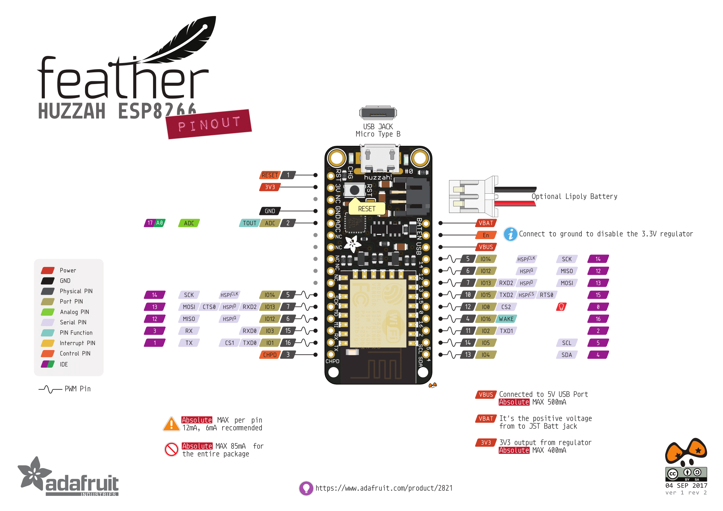
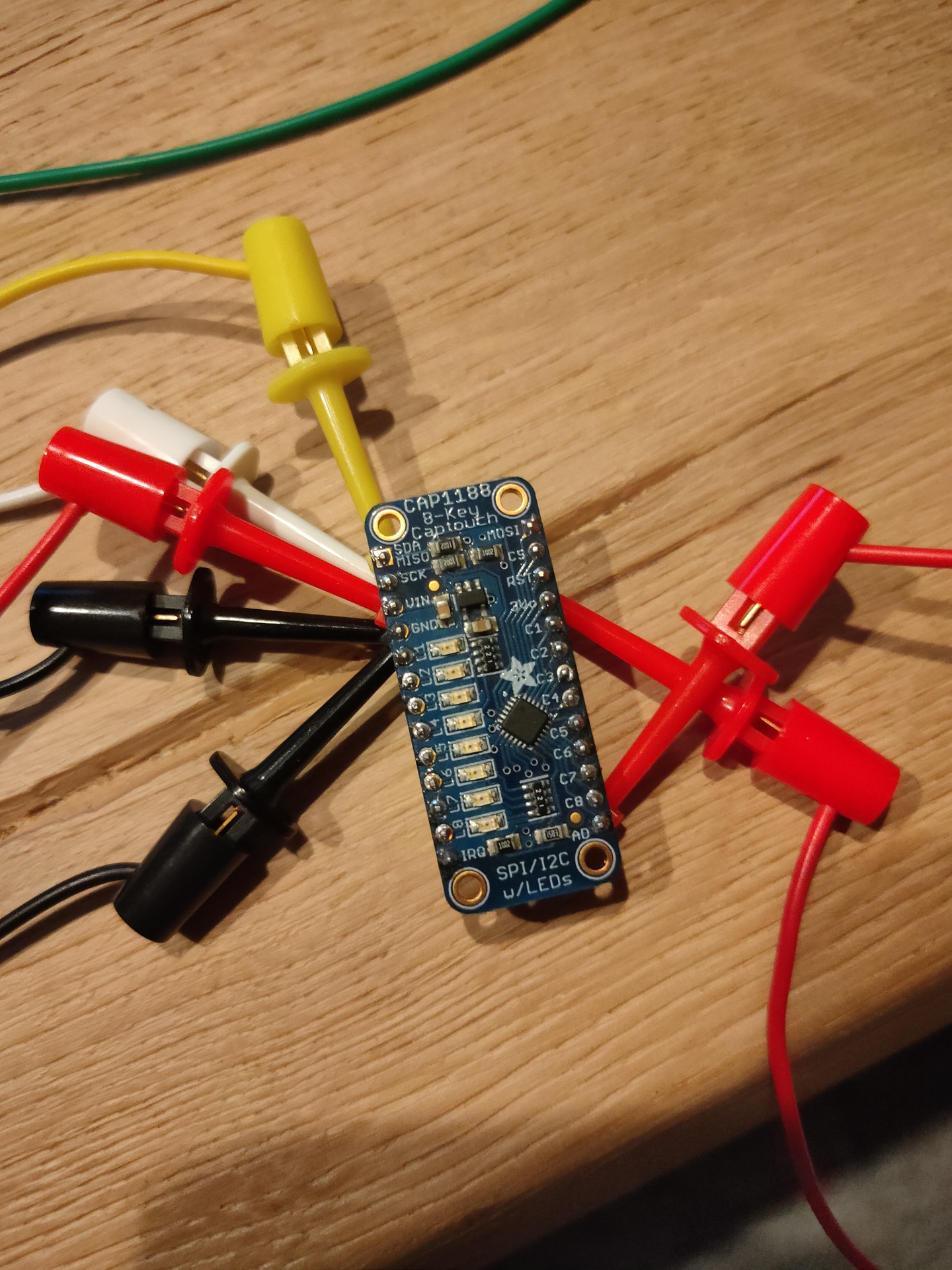
Finding the right pins or above pinout was the hardest part.
The sketch reads the pins binary so value 129 is first and last bit.
Now i have to get the sound sounding a little better and add frequencies and fingersettings to the sketch to get a minimal electronic bagpipe. (V3 it is .. )
To be continued ..