(Live real time using text (code) to make music and visuals)
Last week, I discovered Strudel. I was playing around with it and thought: “This would be perfect for Tyrone”. He is/was the main musical artist in our Group.
Strudel REPL is a web-based, live coding environment for creating music, based on the Tidal Cycles pattern language. It allows users to write and edit code in a browser to instantly hear the music it produces, with features like visual feedback and an interactive tutorial to help beginners and experts. The “REPL” stands for Read-Eval-Print Loop, a common term for interactive programming environments where you can type code, and the system immediately evaluates it and prints the result.
I can make some simple patterns, but I discovered that it can be used multiuser with realtime synthesizer named Hydra. I’m better doing visuals, than creating realtime digital music. Check out https://www.henriaanstoot.nl/?s=shaders – for my previous shader programming posts. (I love playing real instruments, let’s keep it that way.)
Hydra video synth is a free, open-source, live-coding environment for creating real-time visuals that runs in a web browser. It uses JavaScript and WebGL to allow users to “patch” together different visual sources and transformations, similar to an analog modular synthesizer, to generate effects like video feedback, generative patterns, and audio-reactive visuals.
It is JavaScript being compiled to WebGL
So using https://flok.cc we can start a multiuser session with realtime live coding.
So the first test session, learning to use Hydra and Strudel together over the internet. Plan is to do a live session for others using a screen projector.
Left Tyrone (Strudel) right me with Hydra.
In the last few days, I made some examples using hydra.
These examples use Microphone for sound reactive, and Webcam for embedded effects. NOTE: These are only in your browser session, nothing is being recorded/stored.
While doing stuff like, making our home a little greener. Smoking meat. Working on diorama’s and my Escape game. I found time to make this little maze game.
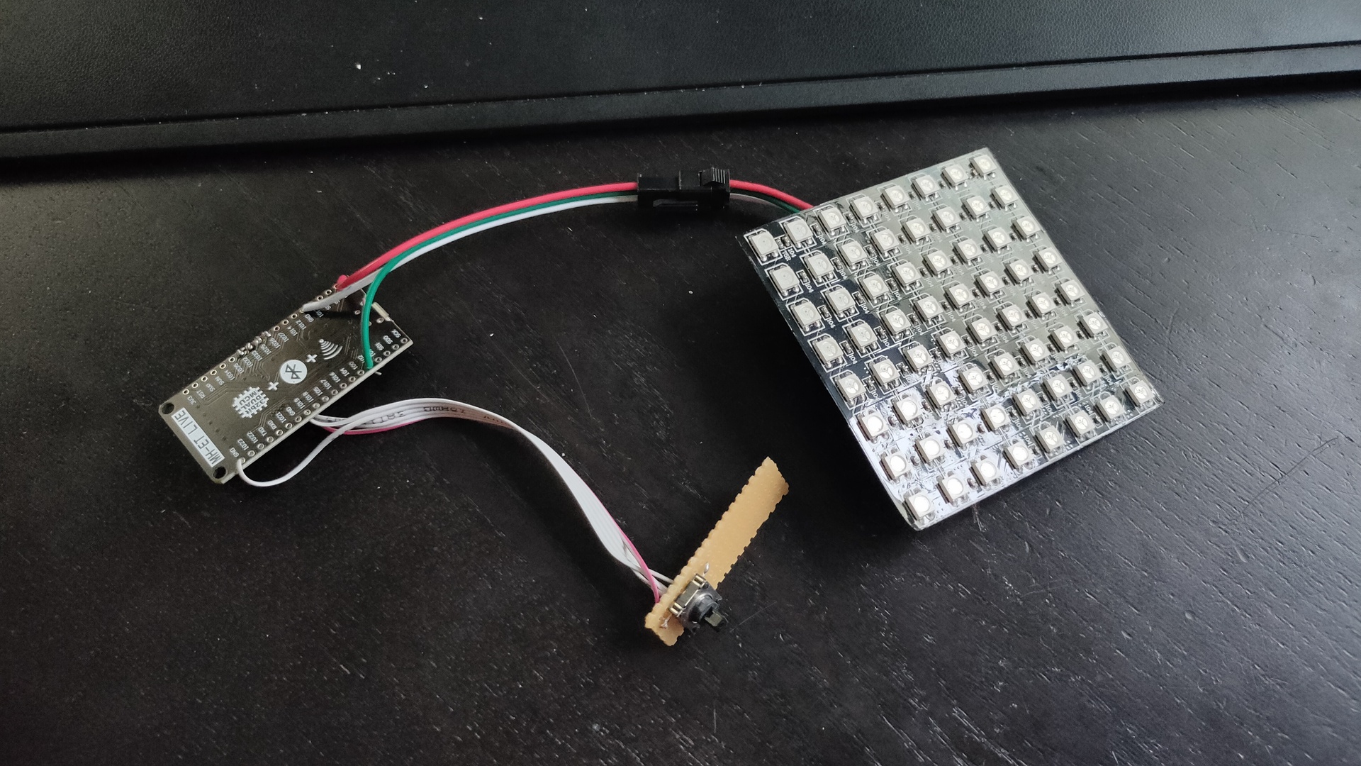
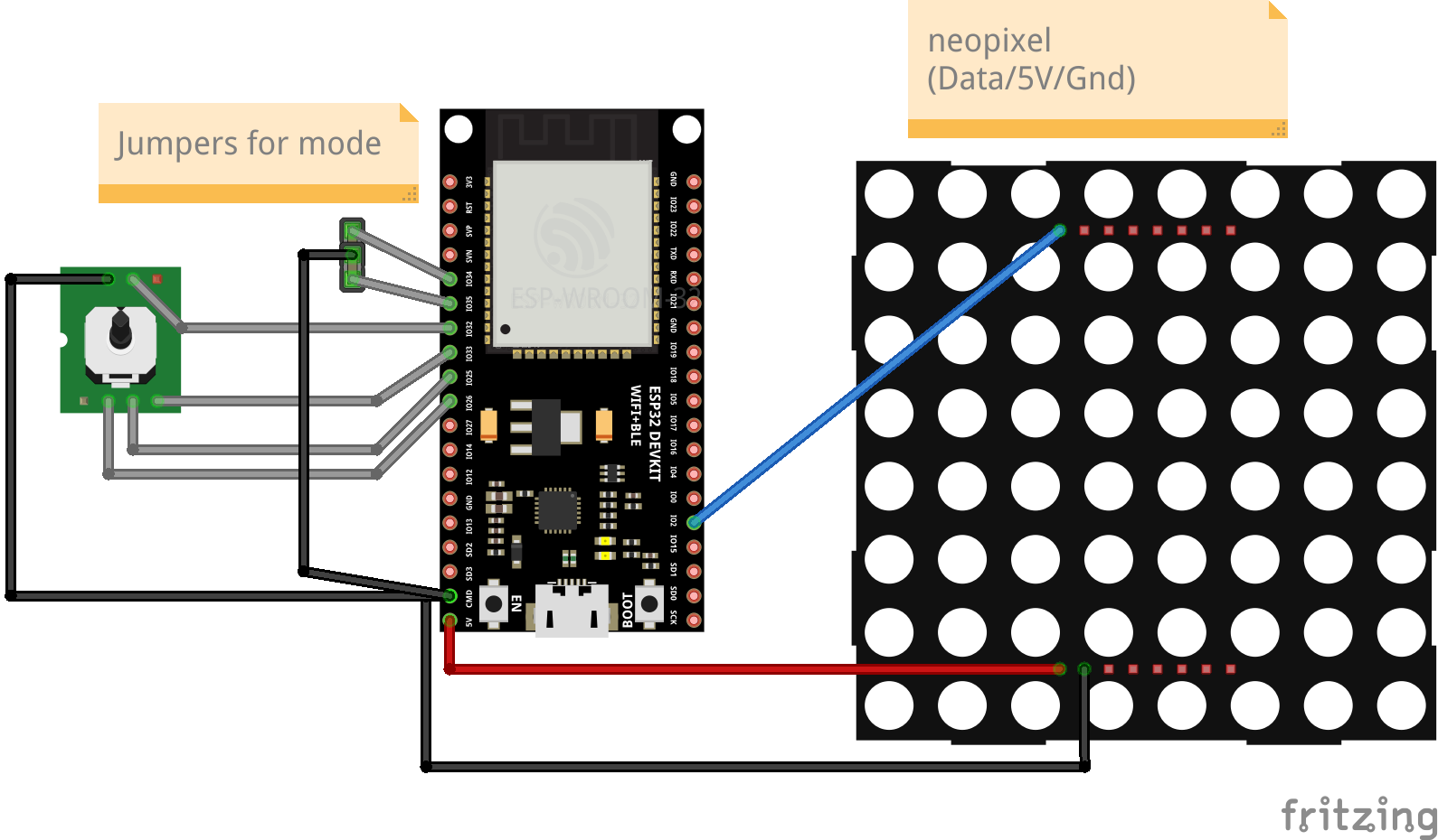
Using an ESP32, mini joystick and a 8×8 led matrix. The objective is to get to the other side of the invisible maze.
It is a blind maze, so you have to figure out the path by trail and error. I found it quite fun and entertaining. (Coline had a hard time finishing the mode 3 maze)
I’ve got 3 settings on the maze: 0 – There is a trail where you have been. 1 – No trail, but only red leds showing walls. 2 – No trail, red reds and a reset to square 0,0 .. so you have to remember the path you previously took.
I’ll add code and schematics tomorrow …
Light blue shows you where you have been
Mode 2 game, reset when hitting a wall
Hitting the end block!
Maze is static at the moment, i’m planning to implement a “Recursive division method” to generate the maze.
Code
#include <Arduino.h>
#include <Adafruit_NeoPixel.h>

// joystick pins
int up=33;
int down=25;
int left=32;
int right=26;
int cursor=32;

// 0 easy = trail // 1 only red walls // 2 = reset to 0.0
int mode=2;

//int trail=32;
int trail=0;

// Which pin on the Arduino is connected to the NeoPixels?
#define LED_PIN    2

// How many NeoPixels are attached to the Arduino?
#define LED_COUNT 64

// Declare our NeoPixel strip object:
Adafruit_NeoPixel strip(LED_COUNT, LED_PIN, NEO_GRB + NEO_KHZ800);

// bits set opening in square
//    2
//   -----
// 1 |   | 4
//   -----
//     0
// so 5 is a passage from left to right (1+4)

int maze[8][8] = {
  4,5,3,6,5,5,5,3,
  6,5,11,12,5,3,6,9,
  14,1,12,5,3,10,12,1,
  12,5,5,3,10,12,5,3,
  2,6,5,9,14,5,1,10,
  10,10,6,5,9,6,5,9,
  12,11,10,6,1,10,6,1,
  4,9,12,13,5,13,13,1,
  };

int displaymatrix[8][8] = {
{ 0,1,2,3,4,5,6,7 },
{ 15,14,13,12,11,10,9,8 },
{16,17,18,19,20,21,22,23},
{31,30,29,28,27,26,25,24},
{32,33,34,35,36,37,38,39},
{47,46,45,44,43,42,41,40},
{48,49,50,51,52,53,54,55},
{63,62,61,60,59,58,57,56}
};

int x = 0;
int y = 0;

void setup() {
// joy
  pinMode(32, INPUT_PULLUP);
  pinMode(33, INPUT_PULLUP);
  pinMode(25, INPUT_PULLUP);
  pinMode(26, INPUT_PULLUP);

// mode set with jumpers
  pinMode(34, INPUT_PULLUP);
  pinMode(35, INPUT_PULLUP);

  Serial.begin(115200);

  strip.begin();
  strip.show(); // Initialize all pixels to 'off'
  strip.setBrightness(10);
// set begin and end pixel
  strip.setPixelColor(displaymatrix[x][y], 0, 0, 255);
  strip.setPixelColor(displaymatrix[7][7], 0, 255, 0);

  strip.show();
//mode select
 if (digitalRead(34) == 0) {
 mode=0;
 if (digitalRead(35) == 0) {
 mode=2;
 } else {
 mode=1;
 }
// finish effect
uint32_t Wheel(byte WheelPos) {
  WheelPos = 255 - WheelPos;
  if(WheelPos < 85) {
    return strip.Color(255 - WheelPos * 3, 0, WheelPos * 3);
  }
  if(WheelPos < 170) {
    WheelPos -= 85;
    return strip.Color(0, WheelPos * 3, 255 - WheelPos * 3);
  }
  WheelPos -= 170;
  return strip.Color(WheelPos * 3, 255 - WheelPos * 3, 0);
}

// reset to start (mode 2)
void reset2start() {
      strip.setPixelColor(displaymatrix[x][y], 0, 0, 0);
    strip.show();
  x = 0;
  y = 0;
  strip.begin();
  strip.show(); // Initialize all pixels to 'off'
  strip.setBrightness(10);
  strip.setPixelColor(displaymatrix[x][y], 0, 0, 255);
  strip.setPixelColor(displaymatrix[7][7], 0, 255, 0);
  strip.show();

}
// finish effect
void rainbow(uint8_t wait) {
  uint16_t i, j;
  for(j=0; j<256; j++) {
    for(i=0; i<strip.numPixels(); i++) {
      strip.setPixelColor(i, Wheel((i+j) & 255));
    }
    strip.show();
    delay(wait);
  }
}

void loop() {
    int isUp = (bitRead(maze[x][y], 1));
    int isRight = (bitRead(maze[x][y], 2));
    int isDown = (bitRead(maze[x][y], 3));
    int isLeft = (bitRead(maze[x][y], 0));
if (digitalRead(up) == 0) {
  if (isUp == 1){
  strip.setPixelColor(displaymatrix[x][y], 0, 0, trail);
  x++;
  if ( x > 7) { x=7;}
  strip.setPixelColor(displaymatrix[x][y], 0, 0, 255);
  strip.show();
  } else {
    strip.setPixelColor(displaymatrix[x][y], 255, 0, 0);
    strip.show();

    if (mode == 2){
      delay(1000);
      reset2start();
    }
  }
}
if (digitalRead(down) == 0) {
  if (isDown == 1){
  strip.setPixelColor(displaymatrix[x][y], 0, 0, trail);
  x--;
  if ( x < 0) { x=0;}
  strip.setPixelColor(displaymatrix[x][y], 0, 0, 255);
  strip.show();
  } else {
    strip.setPixelColor(displaymatrix[x][y], 255, 0, 0);
    strip.show();

    if (mode == 2){
      delay(1000);
      reset2start();
    }
  }
}
if (digitalRead(left) == 0) {
  if (isLeft == 1){
  strip.setPixelColor(displaymatrix[x][y], 0, 0, trail);
  y--;
  if ( y < 0) { y=0;}
  strip.setPixelColor(displaymatrix[x][y], 0, 0, 255);
  strip.show();
  } else {
    strip.setPixelColor(displaymatrix[x][y], 255, 0, 0);
    strip.show();
    if (mode == 2){
      delay(1000);
      reset2start();
    }
  }
}
if (digitalRead(right) == 0) {
  if (isRight == 1){
  strip.setPixelColor(displaymatrix[x][y], 0, 0, trail);
  y++;
  if ( y > 7) { y=7;}
  strip.setPixelColor(displaymatrix[x][y], 0, 0, 255);
  strip.show();
  } else {
    strip.setPixelColor(displaymatrix[x][y], 255, 0, 0);
    strip.show();

    if (mode == 2){
      delay(1000);
      reset2start();
    }
  }
}
if (x ==7 && y == 7){
  strip.begin();
  strip.show(); // Initialize all pixels to 'off'
  rainbow(20);
}
delay(200);

}
MCH2022 is a nonprofit outdoor hacker camp taking place in Zeewolde, the Netherlands, July 22 to 26 2022. The event is organized for and by volunteers from the worldwide hacker community.
Knowledge sharing, technological advancement, experimentation, connecting with your hacker peers and hacking are some of the core values of this event.
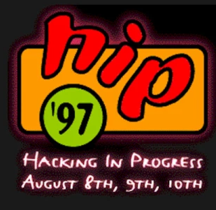
MCH2022 is the successor of a string of similar events happening every four years since 1989. These are GHP, HEU, HIP, HAL, WTH, HAR, OHM and SHA.
I’ve bin to several of these big events. Besides these big events are many different smaller events (wannull, ne2000 etc).
First one i’ve been was HIP97. I went with Bigred at that time. I had to get the tickets at that time, he didn’t had a handle at that time. It was Monique who came up with his new nick.
After HIP97 there was HAL2001 WTH2005 and OHM2013 which i was present. HAL2001 the whole ICEcrew was present, WTH a part of them, OHM a few and i was with a few PRUTS friends.
Now i was with my girlfriend, AND with Bigred again! Loads of fun and memories. Had not seen Bigred since a inbetween hacker party at my place. So ’97 and now ’22 .. jeez 25 years!
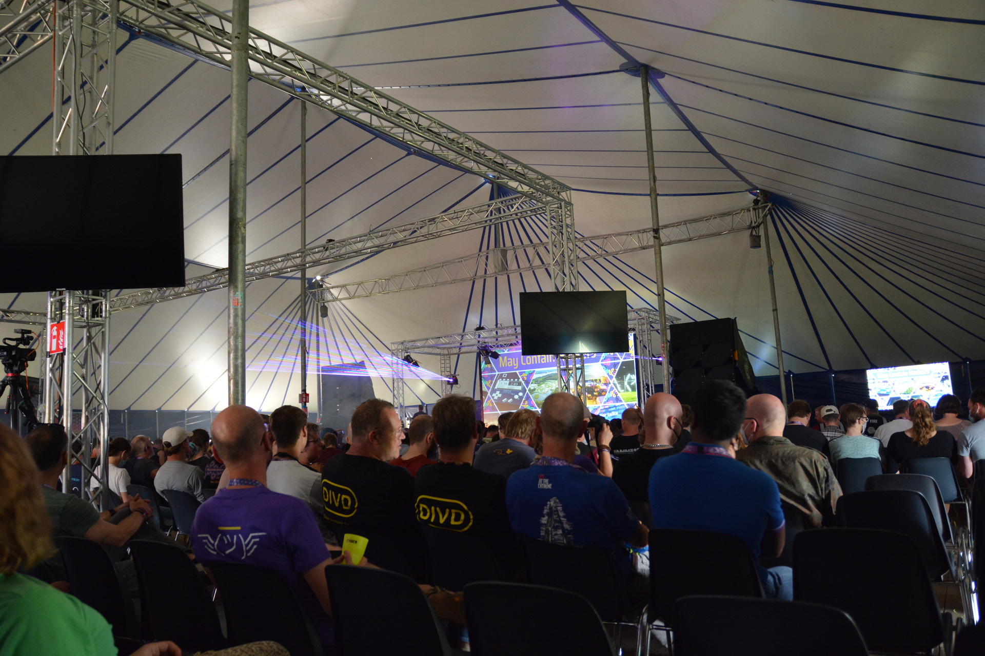
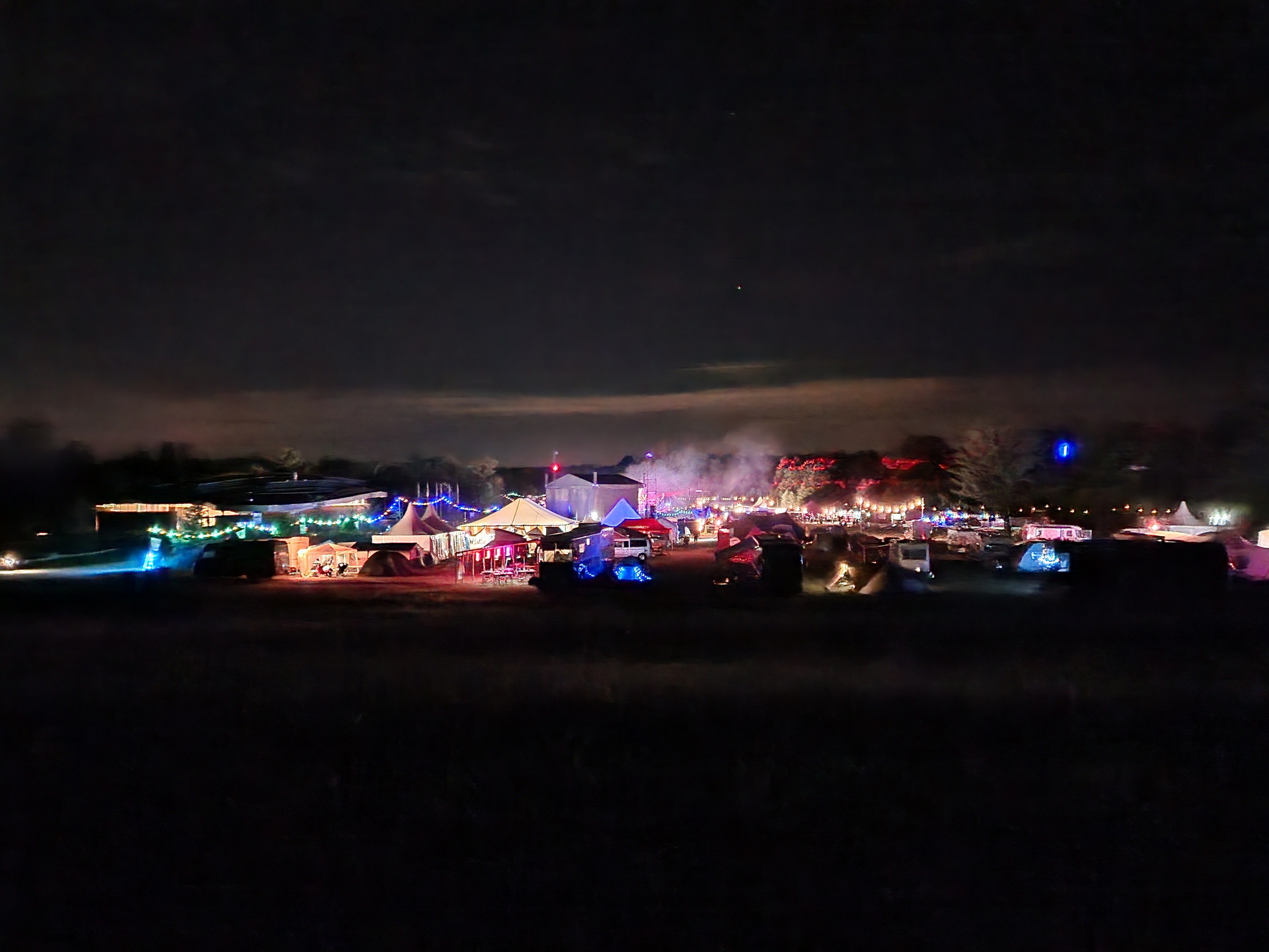
So MCH, it was great again. Loads of stuff to do and to see. Weather was … okay. Two days where really hot, one day some light rain but a load of wind. Our neighbours tent collapsed, beer tents where reenforced. First campsite with a supermarket! Music stage was awesome, lasers and fire!
I went to a lot of talks, even my girlfriend found some she was interested in.
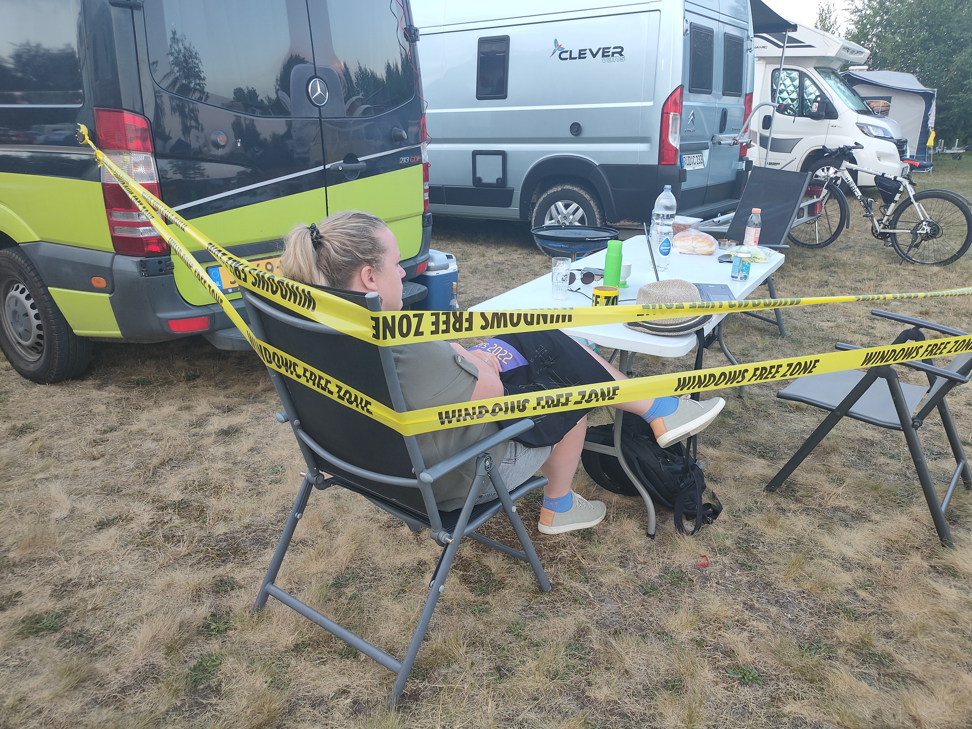
OpeningAt nightLast time my tapeTinkeringtar cz ourstuff.tgz
This was the last time i’ve brought my “Windows free zone tape” This big roll of tape was used on many occasions. I got this roll somewhere < 2000, I did a search but couldn’t find anything mentioning it on the web. Maybe some archive.org entry?
Starting a Home Computer Museum (which i almost did in the past)
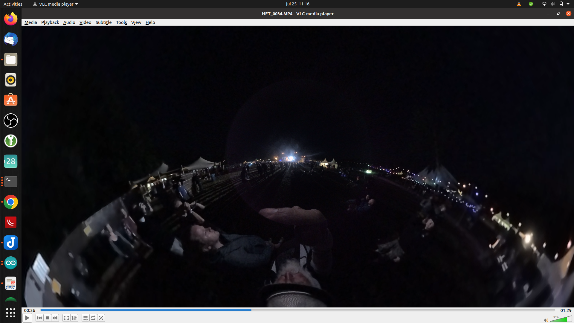
streaming 360 video (going to try this with my Vuze XR Camera)
Non-Euclidean Doom: what happens to a game when pi is not 3.14159… (Really enjoyed this one)
Hacking the genome: how does it work, and should we?
And more
Besides the talks i’ve done some workshops:
Micropython on the badge (see my other post)
Kicad – PCB designing
Meanwhile we where looking at all the villages and hackerspaces. Loads of interesting people to meet. Like our neighbour two tents futher, he was also a home-brewer, and he brought a minifridge with beer taps connected to it.
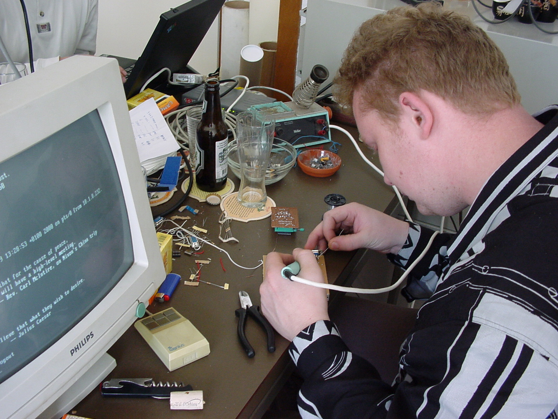
When back at our tent or Bigreds Campervan, we talked about differences now and then. New technology, what we’ve been upto in the last years and tinkering, loads of tinkering.
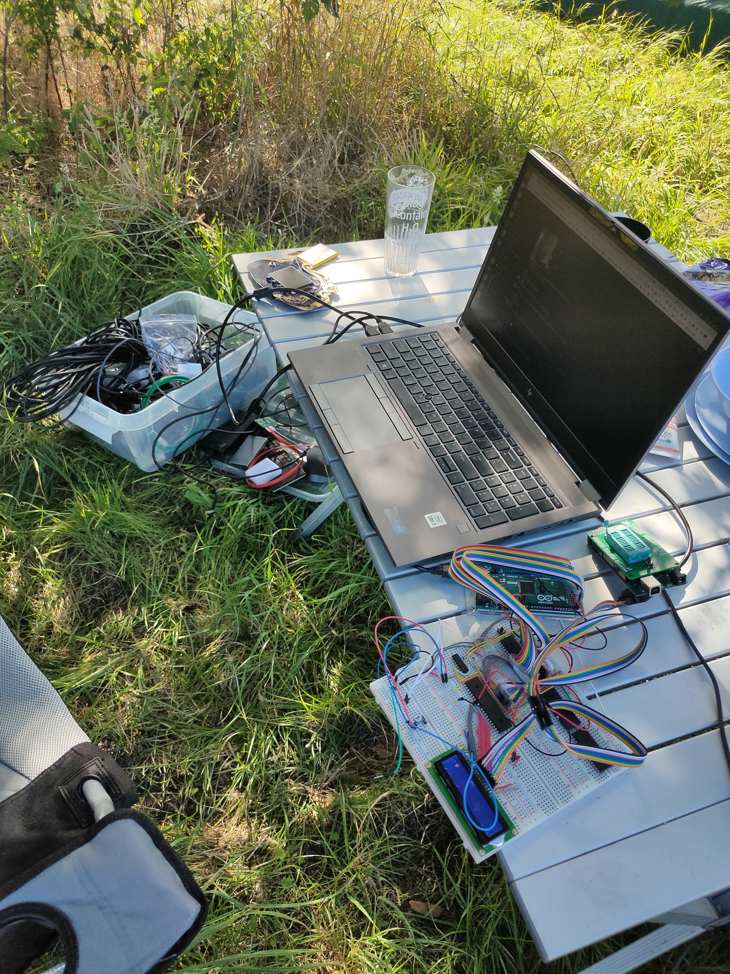
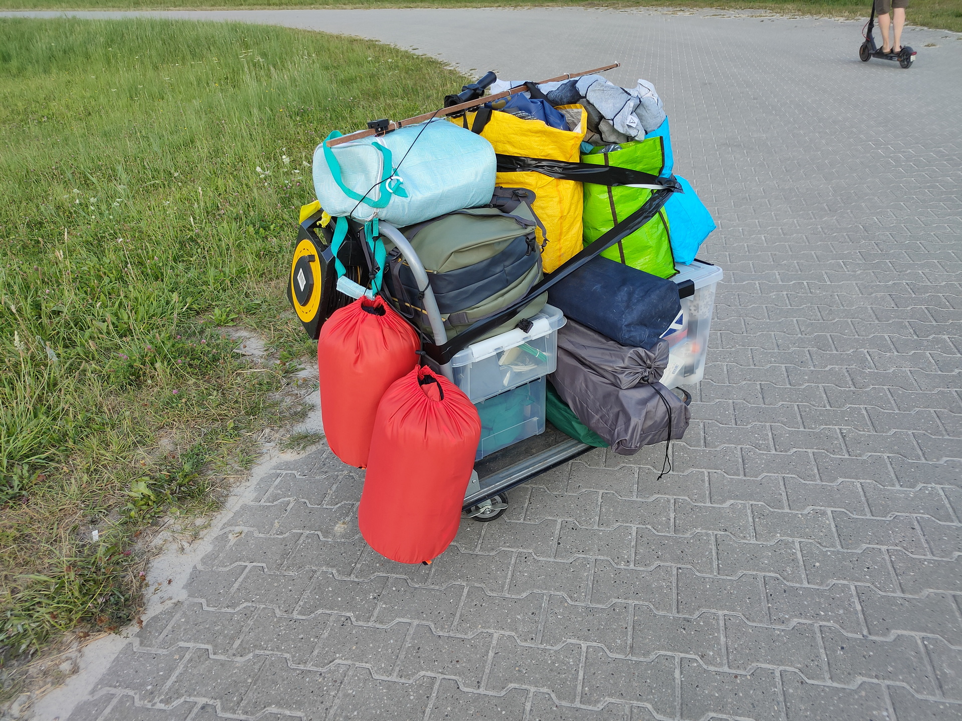
I’ve brough a big plastic container with .. ehh “things to do ….”
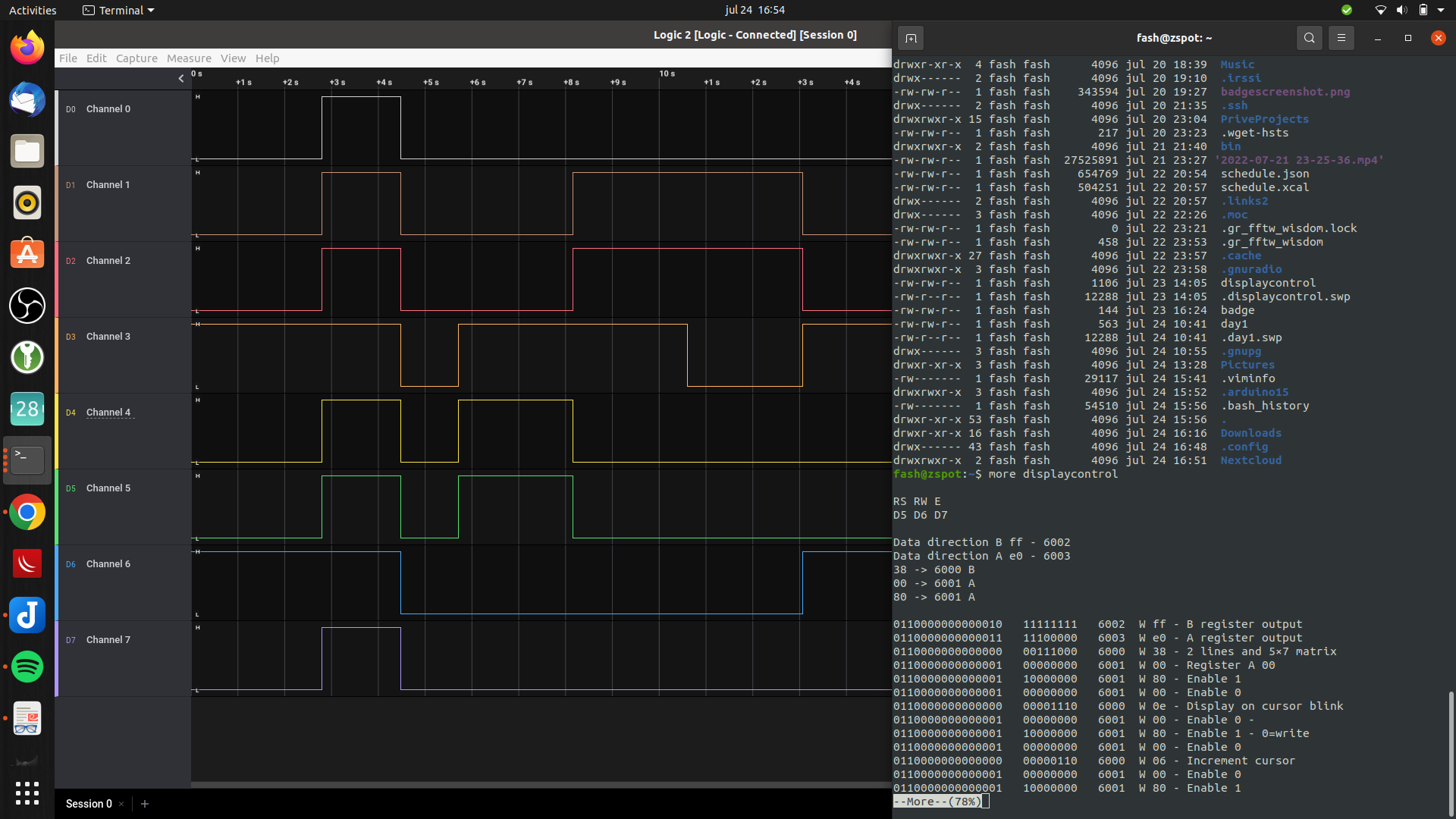
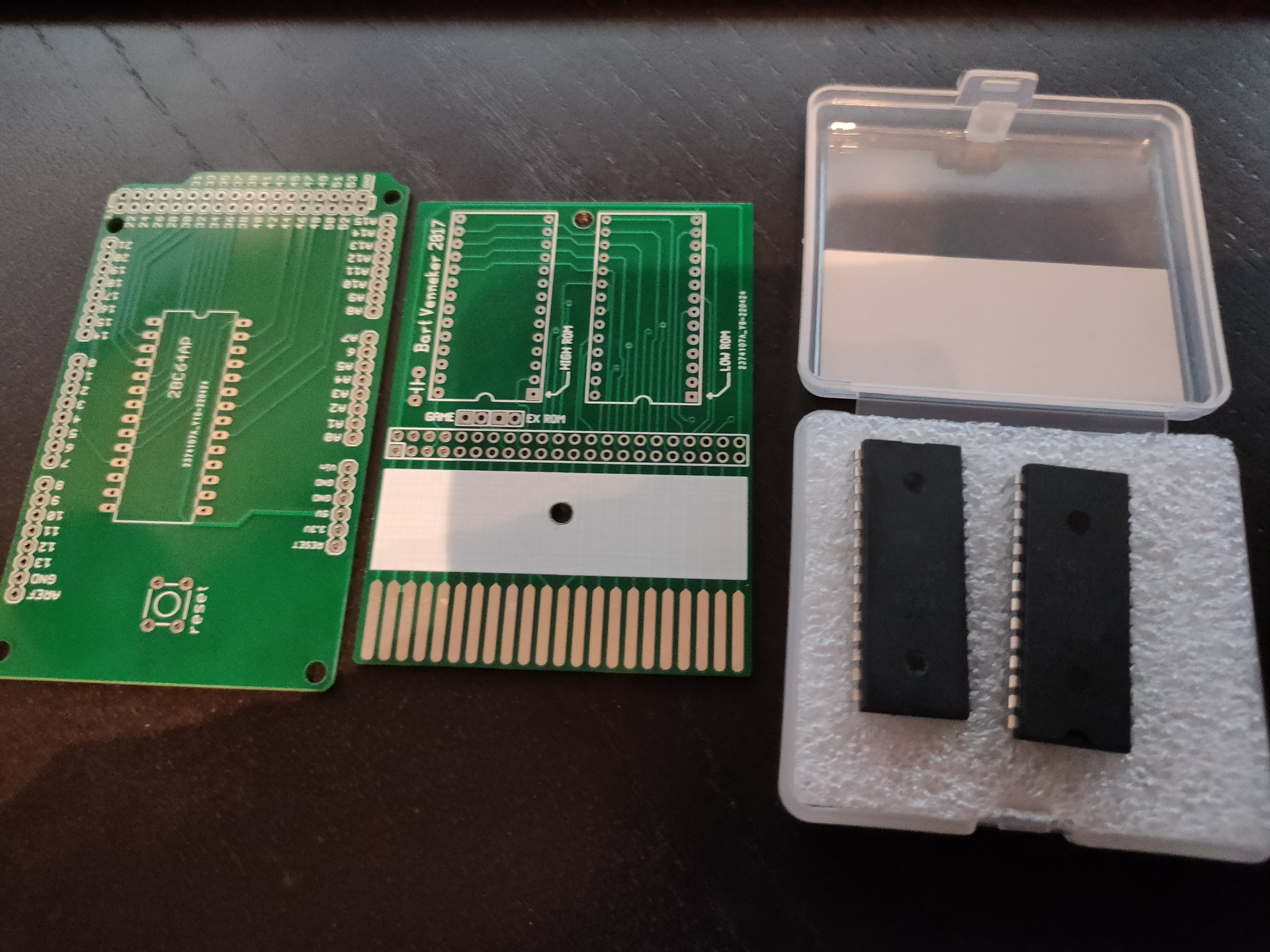
My 6502, bigred helped me debugging the 16*2 display. (Luckily his campervan was packed with electronics!) We cannibalized one of his projects for a display, and re-flashed his eeprom programming arduino to test my display. ( The arduino i had to reflash later to program a rom he had given me for my 6502. ) Other toys he gave me: Print for the programmer, and a C64 Cartridge print for Exrom and Game.
Mini C64 with a little screen and raspberry zero.
5050 ledstrip (didn’t had time to reprogram this for our mood-light)
Handheld gamehat: Bigred found some old games he played when he was young
Mikrotik router, because i wanted to make a dmz for my girlfriends laptop. (MS)
Playing around with my Vuze XR camera
Huskycam, which i’m planning to use on a racetrack
DVB-T DAB FM Stick, got some hints and tips from Bigred. (Note to myself … fix the antenna!)
My Arduino touch bagpipe player with i2c
The wifi deauther, which has a display which i wanted to use to make a programmable clock for my 6502. Using a rotary encoder and the display to control the speed in Hz.
I spend many hours playing with the Badge and Kicad
Wrote some 6502 assembly, arduino sketches, php, bash and micropython.
While playing around with the badge i got some things working easily. Spinning logo and blinky leds. Next goal to achieve was, to get the gyroscope to control the angle of spinning. Most of the code worked, but the gyro values stayed zero! (After many hours …. you have to start/enable the chip/measurements on the bno055 first! .. duh! )
I didn’t had my dev directory from my main battlestation synced in my nextcloud, so changing things for the 6502 was a b*tch. Used vasm and acme to generate a bin file to use to fill the rom. Didn’t like the eeprom programmer program, because i could not easily check the rom contents. Have to look into that later on.
While learning to use Kicad, which i only had been using to draw schematics (besides fritzing) , i learned to create a pcb. Which gave me the idea to make a print for the power-on-reset for the 6502. Which is going to be the first PCB by ordering, instead of the old skool messing around with DIY print making. (see next post)
….. Oh, why my display was not working? I even connected my 8bit logic analyzer to the pins of the display.
Everything was correct. But i didn’t use a variable resistor for the contrast. Just a simple resistor i could find. Luckily … bigreds stash. All those hours debugging, all for one resistor! (I have to mention, we had a suspicion halfway. But it was too hot and we where too lazy to go to Bigred’s campervan, to get a potentiometer. )
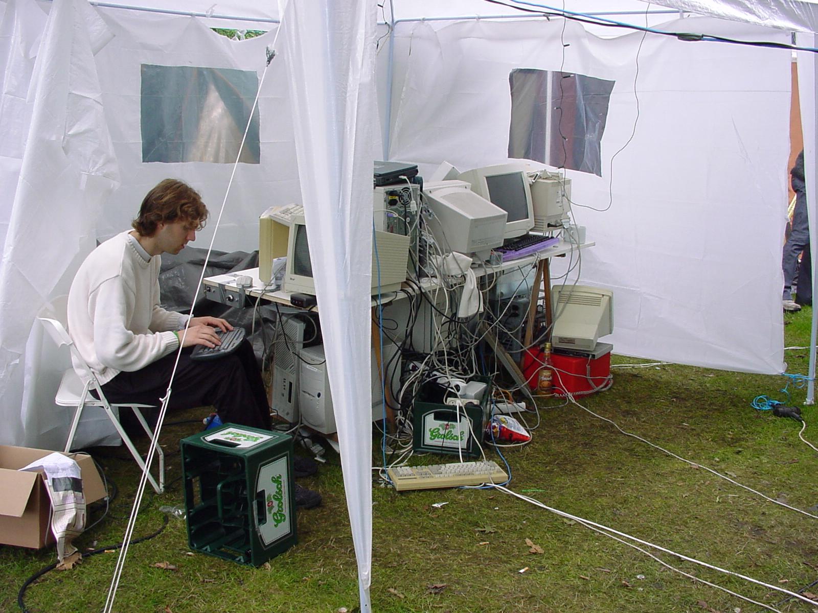
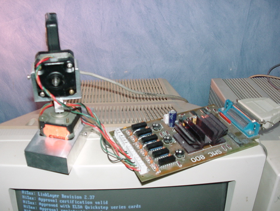
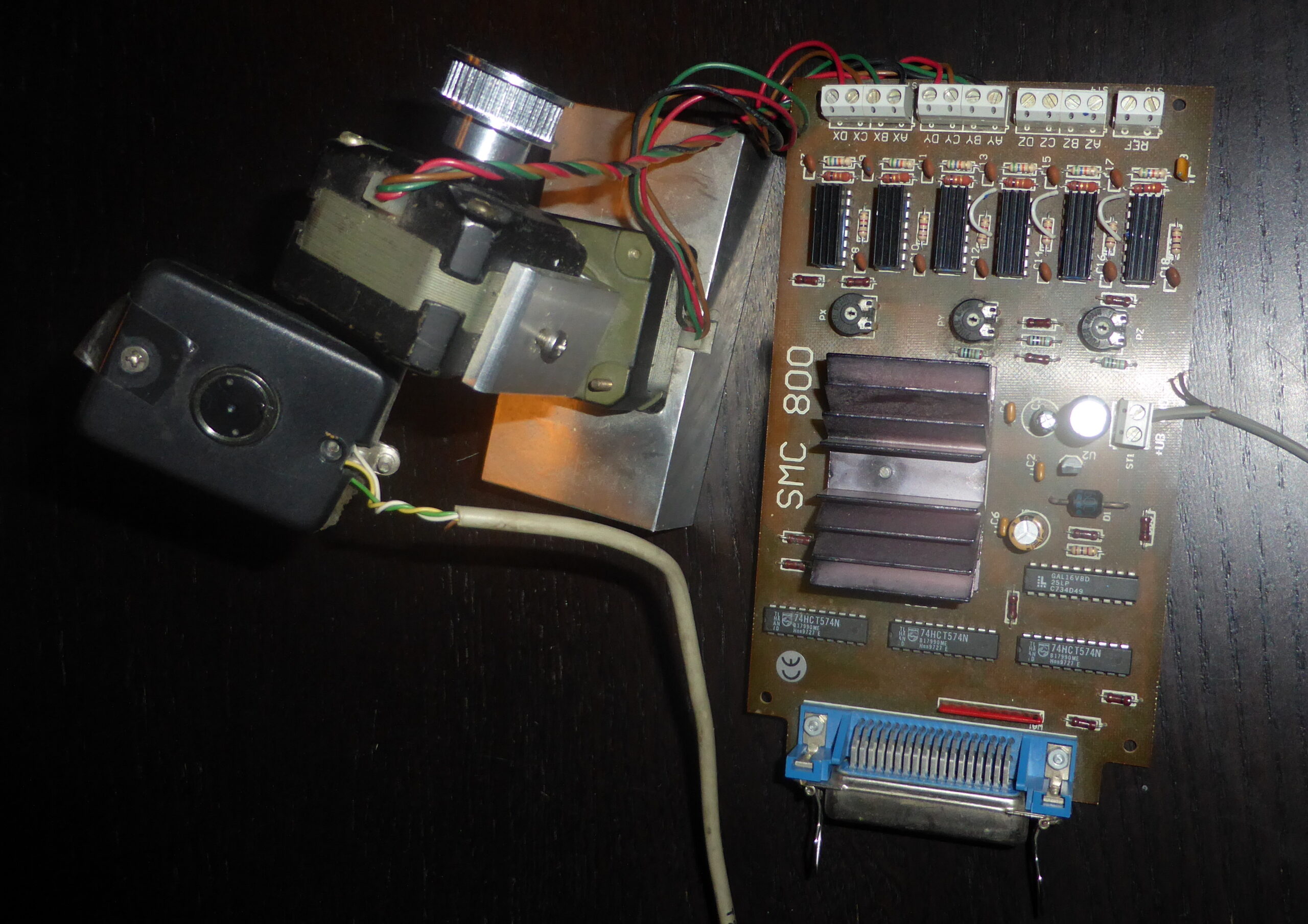
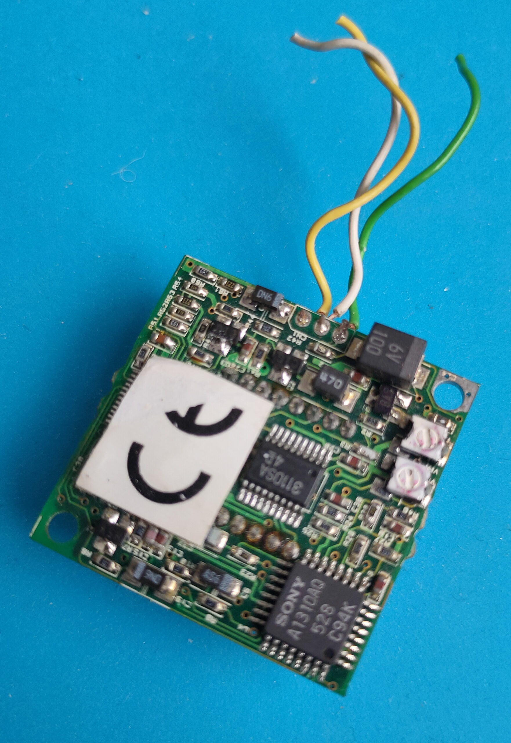
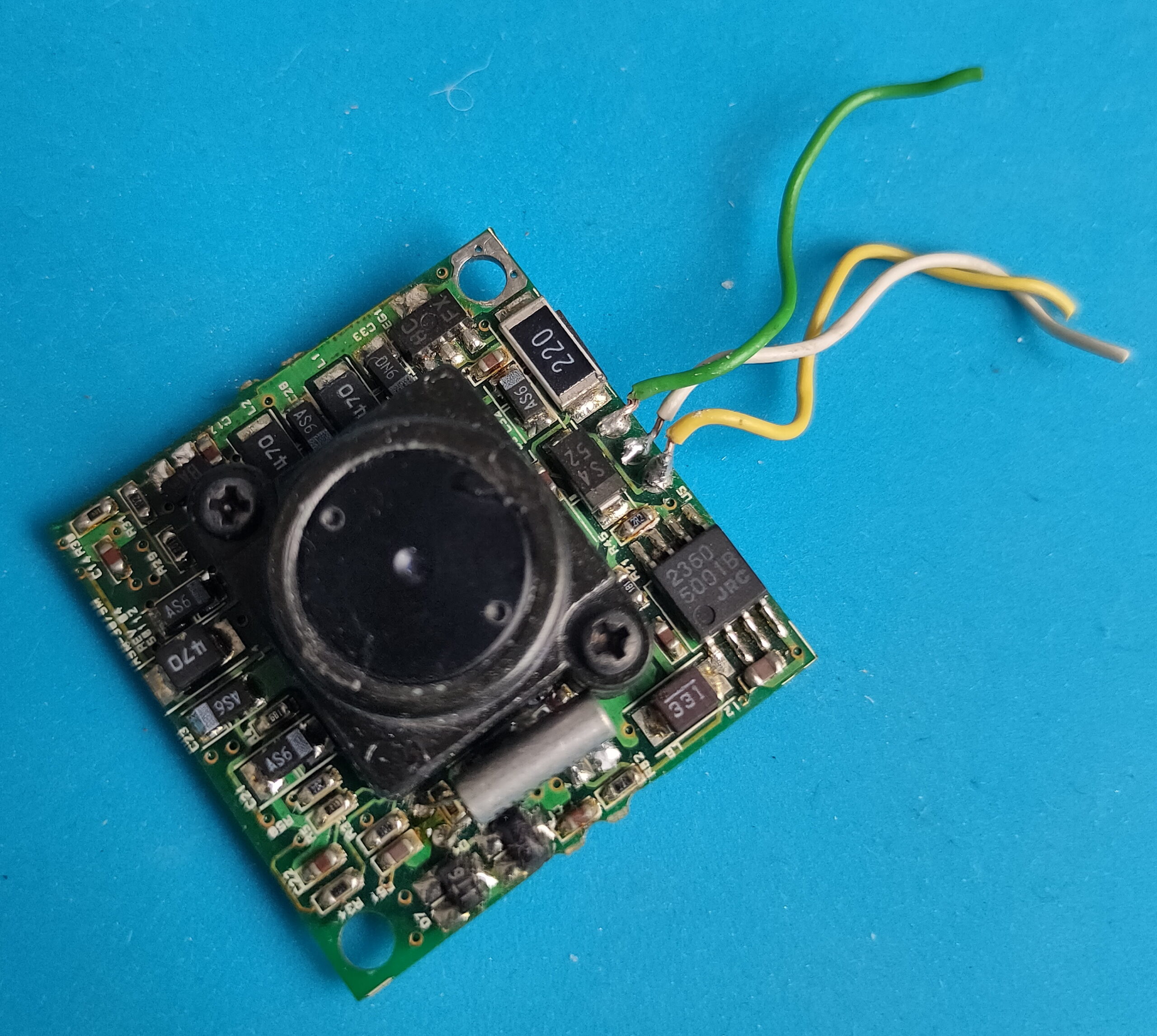
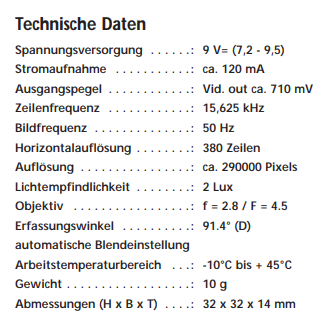
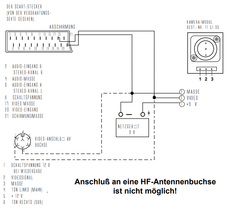
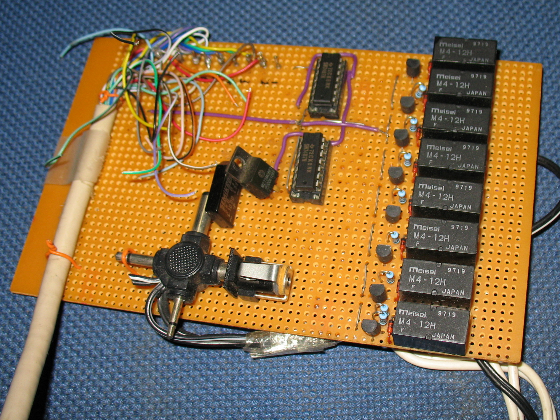
Using a steppermotor controller with two motors. A video capturing device (videoblaster) and a mini B/W camera.
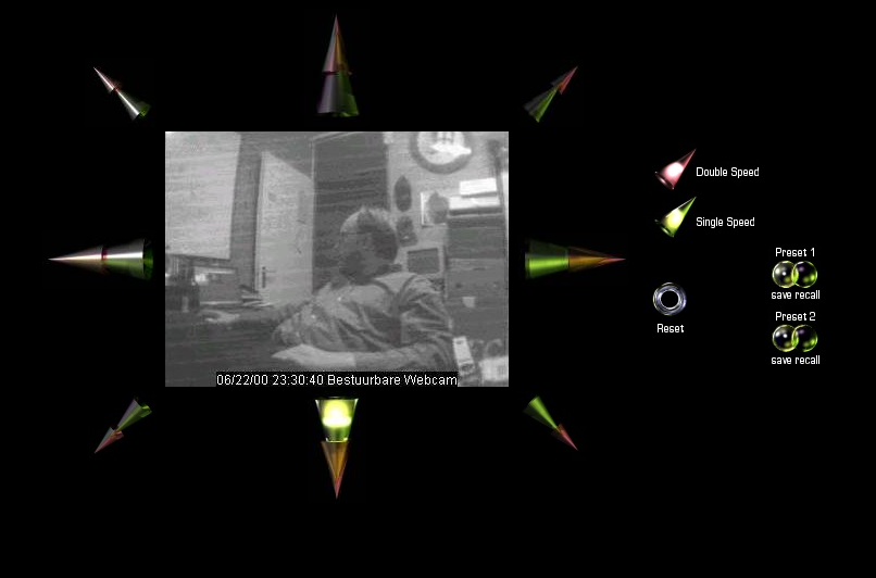
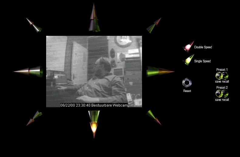
Web interface with glassbuttons effects which i rendered using Bryce.
Up/down/left/right and diagonal
Red double speed green single speed
Reset view
2 Presets with save and recall
Setup with parallel cable
Written software in html and some CGI scripts. Perl and C.
#include <asm/io.h>

# C Code for moving left

int main(int agrc,char agrv[])
{
  int i,wachten;
  int richting1[8]={0x27,0x2d,0x1c,0x0d,0x03,0x09,0x38,0x29};
  int richting2[8]={0x29,0x38,0x09,0x03,0x0d,0x1c,0x2d,0x27};
  ioperm(0x378,3,1);
  ioperm(0x37a,3,1);
  wachten=100;


for (i=0; i<=7; i=i+1)
        {
        outb(richting2[i], 0x378);
        outb(1, 0x37a);
        usleep(wachten);
        outb(0, 0x37a);
        usleep(wachten);
        outb(1, 0x37a);
        usleep(wachten);
        }

 return(0);
}
#!/usr/bin/perl
# Perl CGI script

# Uses 204 no content trick to stay on same page
use LWP::Simple;
my $img = get ('http://10.1.0.1/cgi-bin/left.cgi');
print "Status: 204 No content\n\n";
Streaming video was done using progressive JPG push. Later i used the capturing command in the loop below.
#!/bin/sh

# push jpg, and update after 1sec
# output mime header

echo Content-type: multipart/x-mixed-replace;boundary=--WebcamRules\n
echo
echo --WebcamRules

# create stream

while true; do
   echo Content-type: image/jpeg
   echo
   cat /var/lib/httpd/htdocs/webcam.jpg
   echo
   echo --WebcamRules

   sleep 1
done
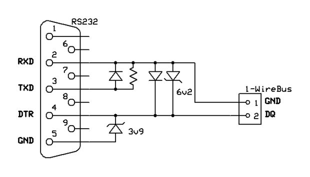
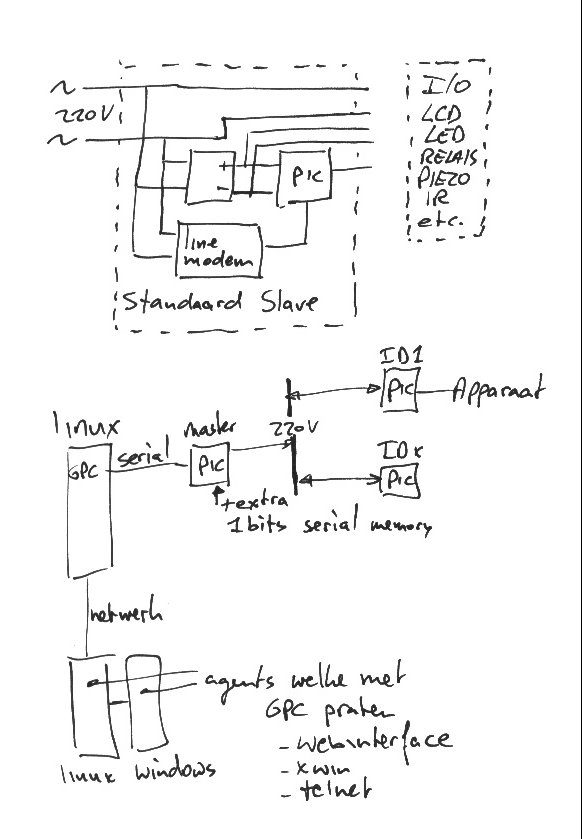
The date of this post is when we worked on GMC’s GPC, but i’ll post some other own made hardware related to domotica.
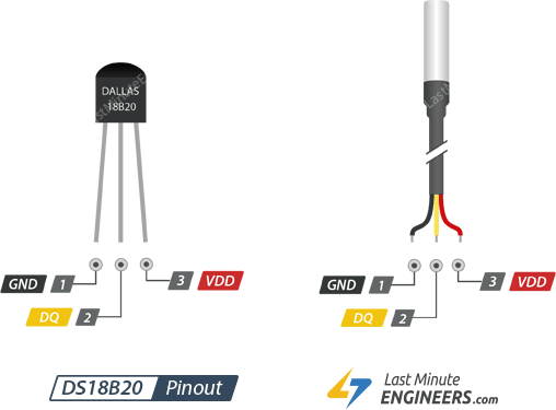
Relais card + one wire temperature sensor (rs232)1Wire to RS232DS18B20
GPC Original Page: https://gpc.metro.cx/gpc/README
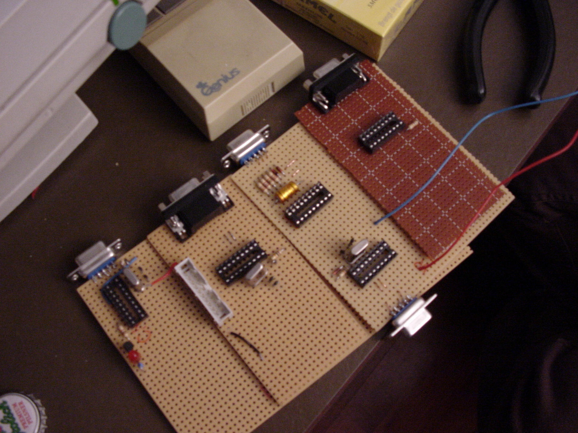
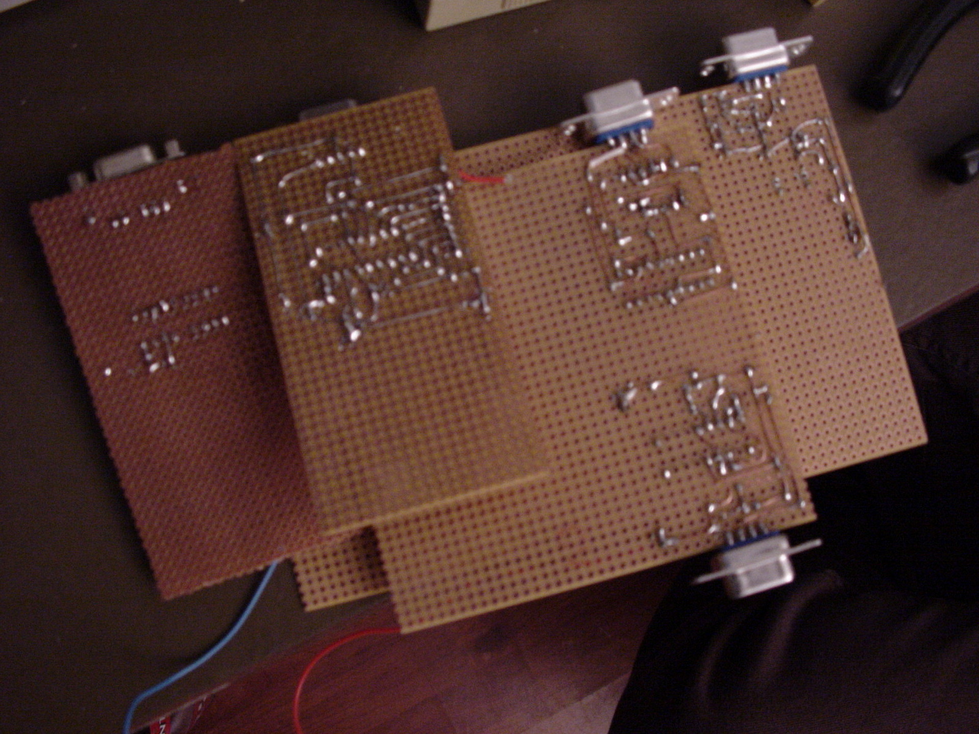
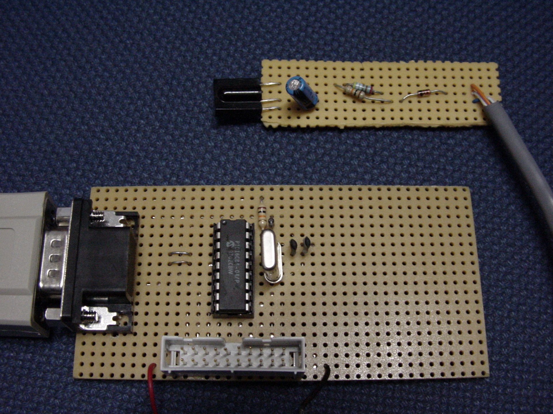
This DIY home automation was written by GMC in C. Later we made little microcontroller prints, which could control/switch lights and more.
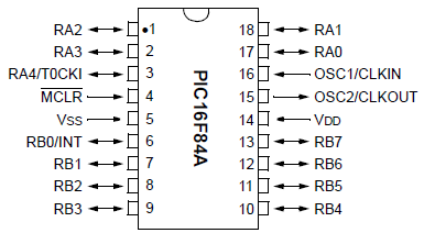
PIC16x84
We uses GPASM as assembler
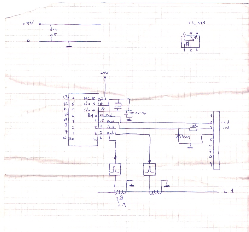
Bigred soldering PIC boards like control units and pic-programmers Below a Infrared receiver (Using Lirc)SchematicPower partPIC Print
One of my schematics
What is this?
=============

 This is the Global Premises Control package. It is intended to be a
complete solution to the DIY home automation. It provides you with a
daemon which will centralize all control functions, and some custom
programs for sound, remote control and things like that.
 The first steps to realizing the goal was made by Koen Martens. He wrote
the first daemon and made the first support programs. Other people got
interested and ported the GPC package to their homes. Since then it seemed
wise to coordinate development to prevent from having three different
versions of the package. It is currently under development and is far from
complete.

History
=======

 15-03-98 - The first initiative
	    With the help of Henri Aanstoot and Marco Geels the first
	    cables were mounted in the ceiling at Waalstraat 136. This
            involved re-dedicating some high voltage lines for the low
	    voltage used by GPC equipment.
	    The next few days Koen Martens spend his time writing software
	    to switch on the lights (which was not possible without
	    software anymore :). This software was very rudimentry and
	    did not feauture the daemon yet.
 28-03-98   Version 1.0 was born.
	    The need for a global way to control the premises arose, and
	    Koen Martens decided to write a daemon which would control the
	    input and output lines, with support programs for the logic.
	    This resulted in global, the gpc daemon.
	    Running on different servers there were programs to control
	    lights and lightswitches (light_control), sound (sound) and
	    the alarm clock (wakeup).
 10-06-98   Version 2.0 (r0.2.0) was born.
	    The support programs containing any logic had vanished,
	    instead the daemon had all the logic encoded in it.
 03-07-98   Version 2.0 still.
	    - Added remote control receiver code.
 29-11-98   GPC r0.3.0
	    - Started coordinated development
 11-12-98   GPC r0.3.1
	    - Security support included, providing a (basic) interface
	      for protecting variables with passwords on a security level
	      clearance basis.
	    - Global notify protocol added, clients can now register one
	      or more variables. This makes the old (0.3.0) polling method
	      obsolete thus reducing the network load dramatically.
	    - Logging library added.

Development
===========

 The development is done on the following beta sites:

 - Subnet
	Location	: Waalstraat 136, Enschede, Netherlands
	Site coordinator: Koen Martens AKA gmc (gmc@freemail.nl)
	Site description: Single floor appartment
			  3 occupants (1 human, 2 rats)
			  P60 32MB RAM running linux
			  486 8MB RAM running FreeBSD
			  486 8MB RAM running linux
			  DEC Writer
			  WYSE terminal
			  The 486 linux machine has the daemon, and is
			  hooked up to the premises.
			  The P60 has a sound card and a RC receiver.
 - Lip-on-ice
	Location	: Lipperkerkstraat 321, Enschede, Netherlands
	Site coordinator: Willem-Jan Faber AKA aloha AKA xtz ( And Henri Aanstoot AKA Fash)
			  (w-jfaber@freemail.nl)
	Site description: Three floor house
			  Four occupants (3 male, 1 female)
			  Connected to three other premises.
			  Computer list not yet in!

 - Venom
	Location	: P. Mondriaanstraat ??, Almelo, Netherlands
	Site coordinator: Sebastiaan Smit AKA venom (wssmit@freemail.nl)
	Site description: Three floor house
			  Three occupants
			  4 computers

 If you would like to join the development, mail me at gmc@freemail.nl.


In progress
===========

 The following projects are in progress right now:
	- A script language to describe the control logic for the daemon
		Koen Martens
	- An cgi interface for the http connectivity
	- Support for sharing variables on multiple daemons

Usage
=====

 Use is for your own risk. We can not be held responsible for any damage
resulted from running any of this software.
 Keeping that in mind, usage is very simple but work needs to be done on
the documentation :)
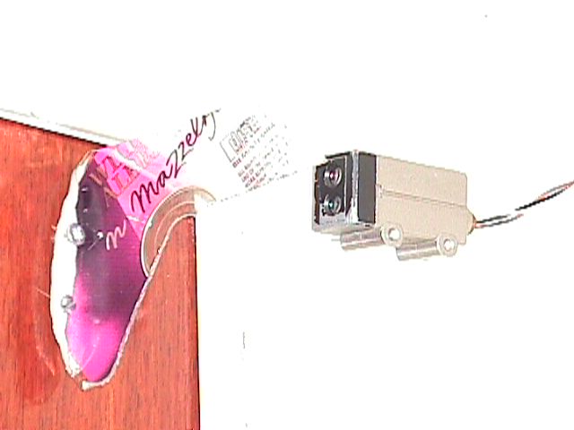
DIY door sensor using a bend CDROM and a sensor i got
I’d would send a signal to our computers and playing a sound sample on our sound system. Also a IRCbot named (lampje) would mention “Backdoor open” in our own channel. (We where running our own IRC servers, interconnected .. because we can. A average of 3 Clients per server sound the way to go .. LOL ) Lampje the IRCbot also controlled the livingroom light and more.
"If something is worth doing, it's worth overdoing."