DISCLAIMER: Do this at own risk, I’m not responsible for loss of data!
Today is the second time I fixed a dead hard disk.
A few years ago, I fixed one containing a university assignment. It took a while, but I managed to get it running long enough to make a backup of the data.
Today, a friend asked me to get the data from a drive containing family pictures.
Below the way I did this.
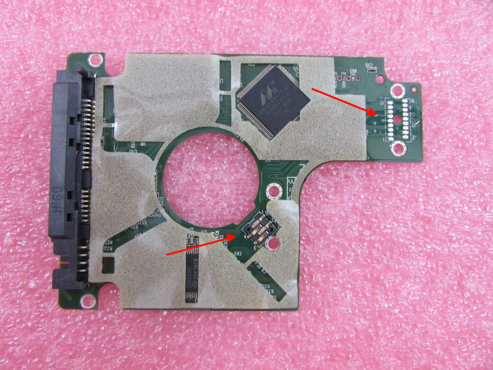
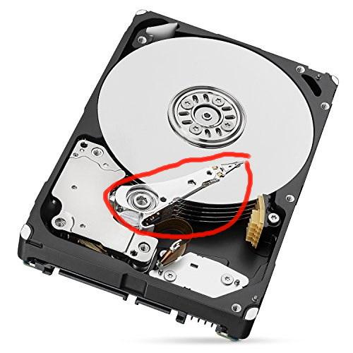
First thing to try: See if PCB has contact problems. Unscrew pcb and clean contacts with ISOPropanol. See red arrows.
If this fails, the head can be stuck. Do below, but be carefull.
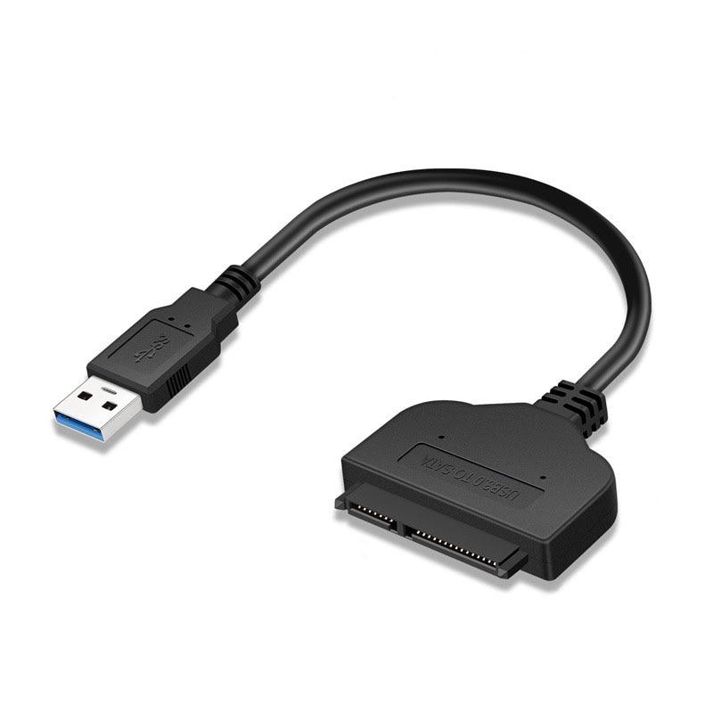
Use a Sata Adaptor so you can move the harddisk around.
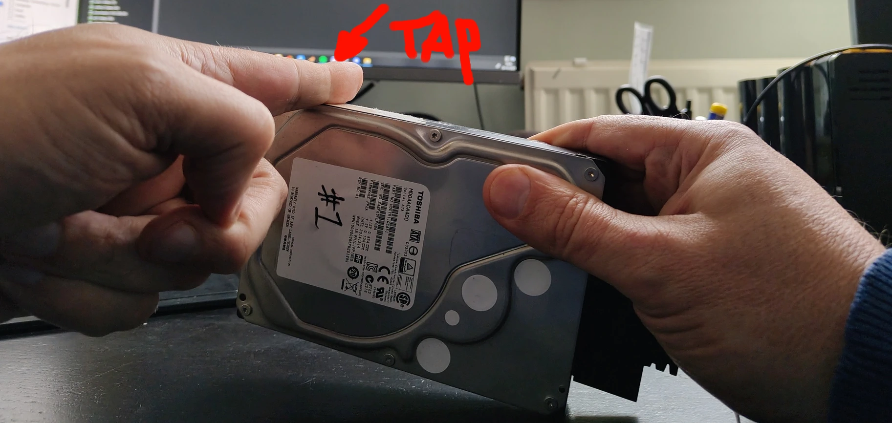
Try to figure out which way the actuator arm is pointing. (Thingy with the read sensor)
Do below while powered up. Point the hard disk with this arm upward. And let it fall vertically on the desk. (Perfectly vertical! Else you may risk head clashing against platters)
When you have a smaller hard disk you can tap the side.
In both cases I managed to get most data from these drives!
substitutions:
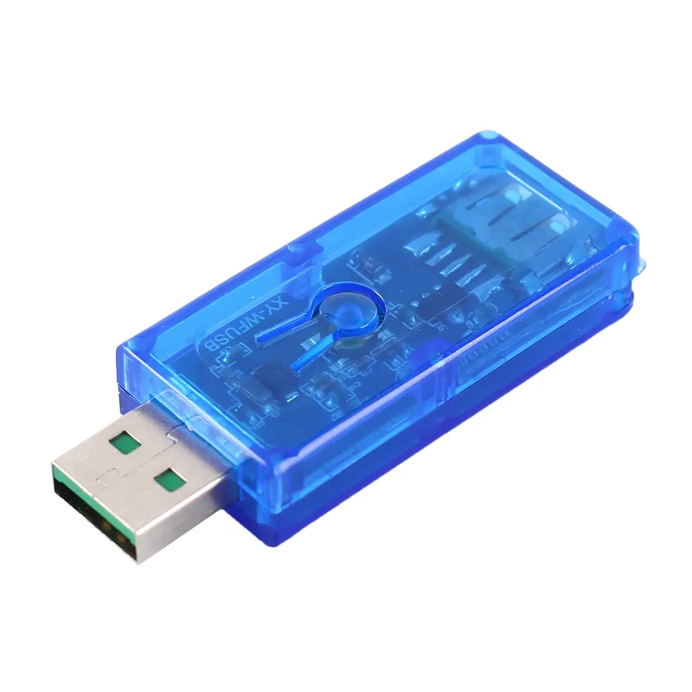
name: usb-relay
friendly_name: "USB Relay"
default_state: "RESTORE_DEFAULT_OFF"
esphome:
name: xyusb1
friendly_name: xyusb1
esp8266:
board: esp01_1m
# Enable logging
logger:
# Enable Home Assistant API
api:
encryption:
key: "ndm8xxxxxxxxxxxxxxxxxjlvrggJv3a1BkY="
ota:
- platform: esphome
password: "12cc9xxxxxxxxxxxxxxxxfb6a01e672"
wifi:
ssid: !secret wifi_ssid
password: !secret wifi_password
# Enable fallback hotspot (captive portal) in case wifi connection fails
ap:
ssid: "Xyusb1 Fallback Hotspot"
password: "xxxxxxxxxxx"
captive_portal:
time:
- platform: homeassistant
# Blue LED
status_led:
pin:
number: GPIO16
# Relay
switch:
- platform: gpio
id: switch_relay
pin: GPIO5
# Green LED
- platform: gpio
pin: GPIO14
id: green_led
inverted: true # start on
# Switch template to link relay and green LED states
# LED is on when relay is off
- platform: template
id: relay
name: "${friendly_name}"
lambda: |-
if (id(switch_relay).state) {
return true;
} else {
return false;
}
turn_on_action:
- switch.turn_on:
id: green_led
- switch.turn_on:
id: switch_relay
turn_off_action:
- switch.turn_off:
id: green_led
- switch.turn_off:
id: switch_relay
# Button
binary_sensor:
- platform: gpio
id: hardware_button
pin:
number: GPIO04
mode: INPUT_PULLUP
inverted: True
on_press:
- switch.toggle: relay
# WiFi Signal Sensor
sensor:
- platform: wifi_signal
name: "WiFi Status"
update_interval: 60s
# Restart button
button:
- platform: restart
name: "Restart"
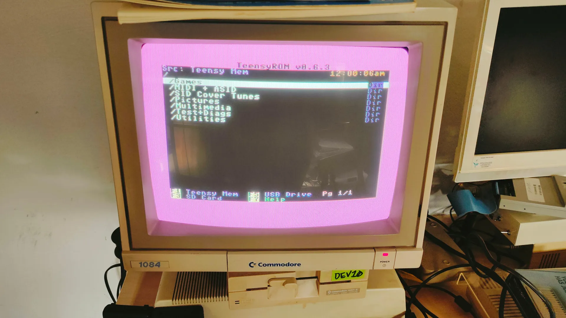
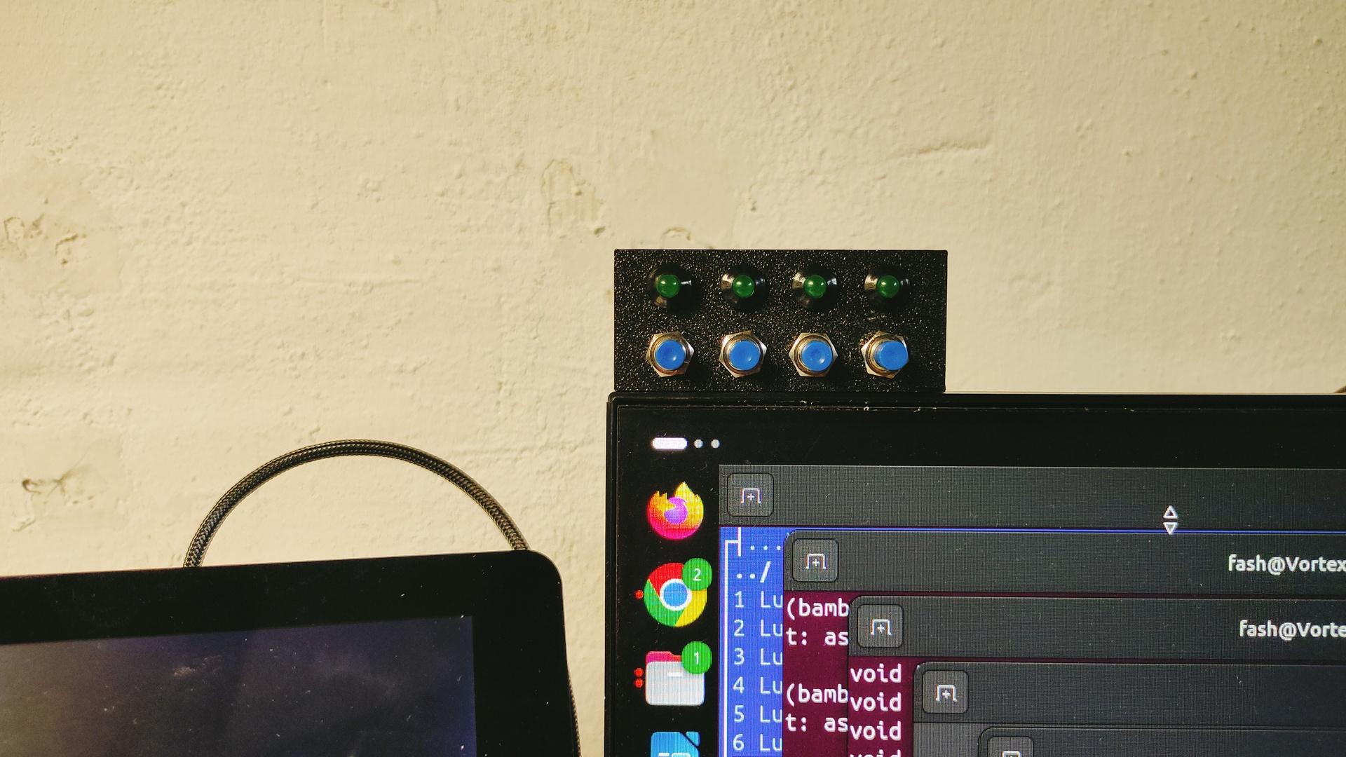
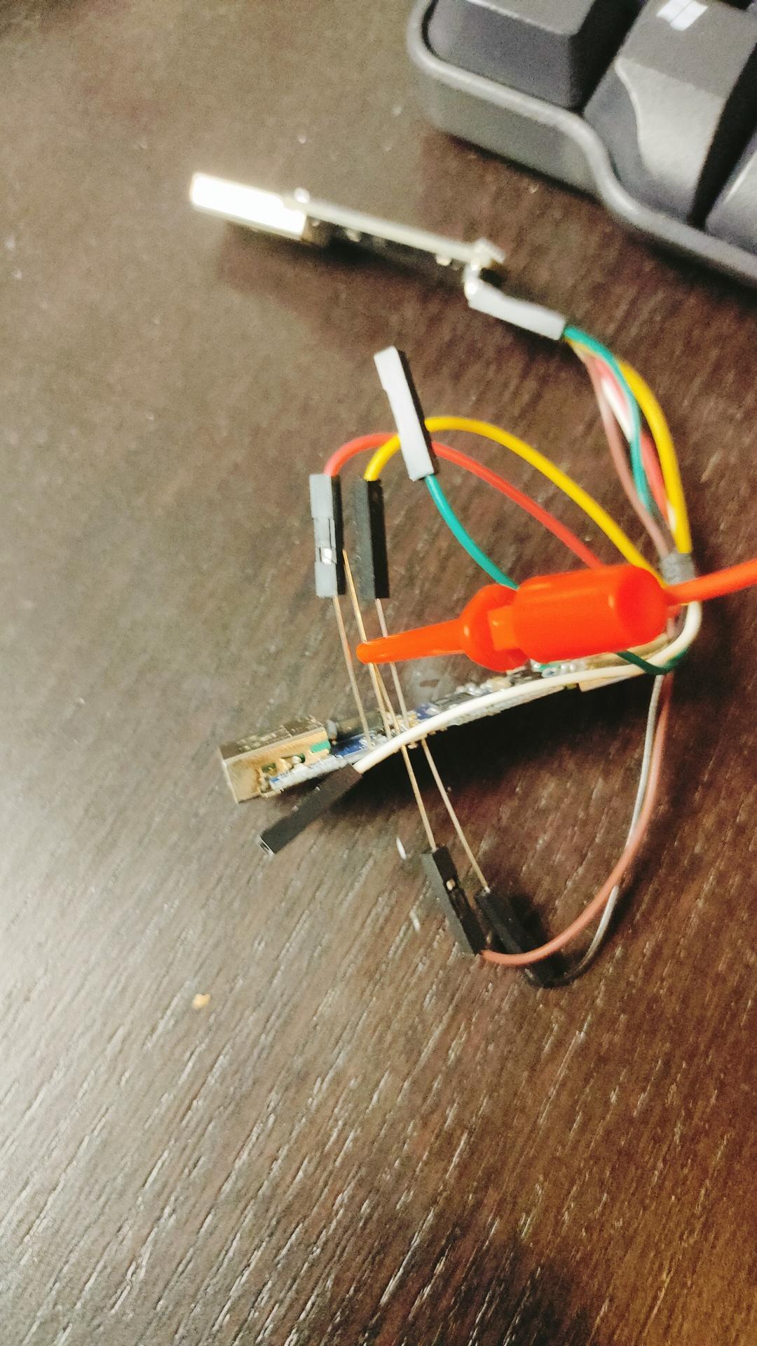
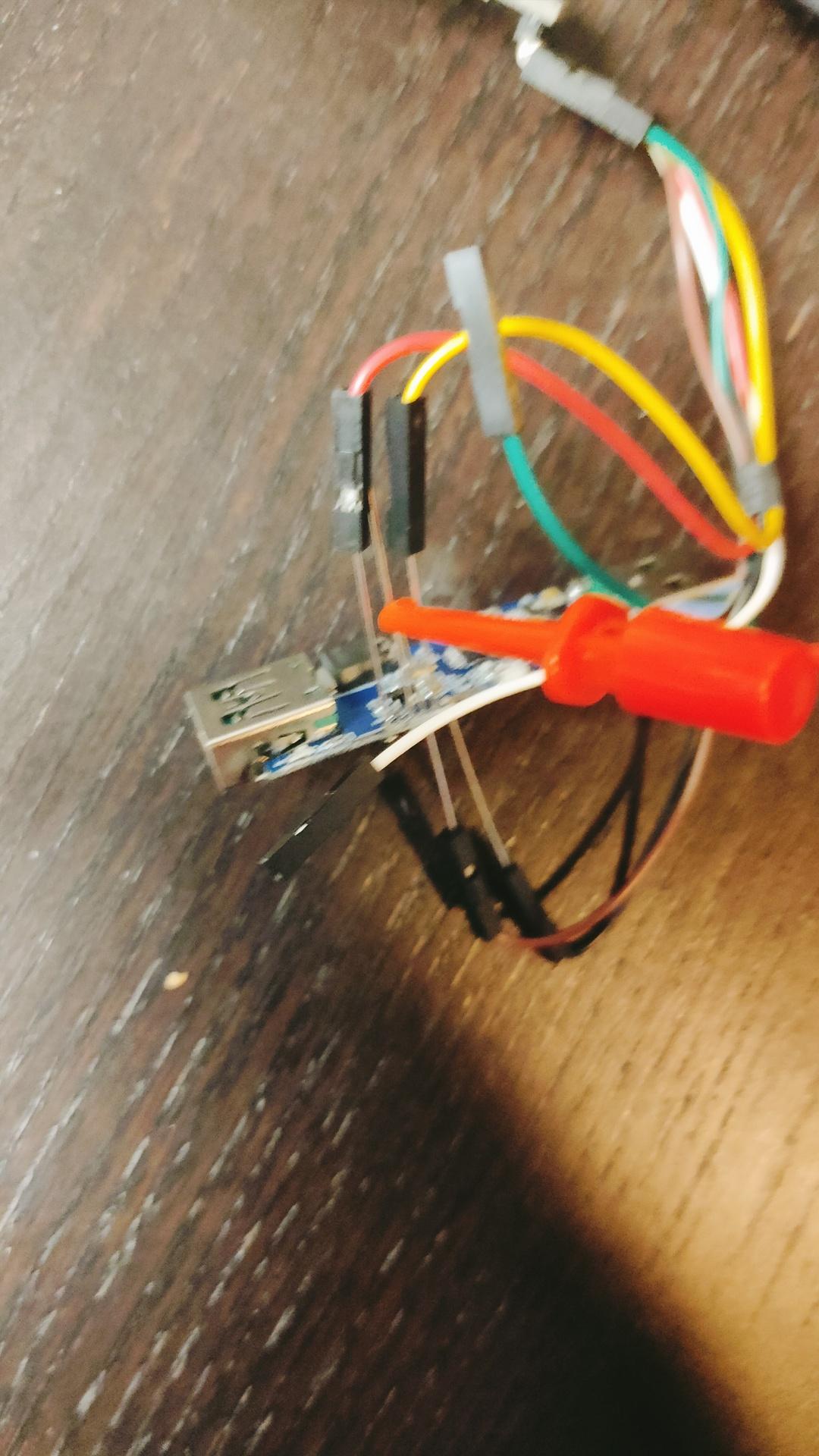
Reflashed my USB Volume button and added a LED-Ring.
Example is green and blue.
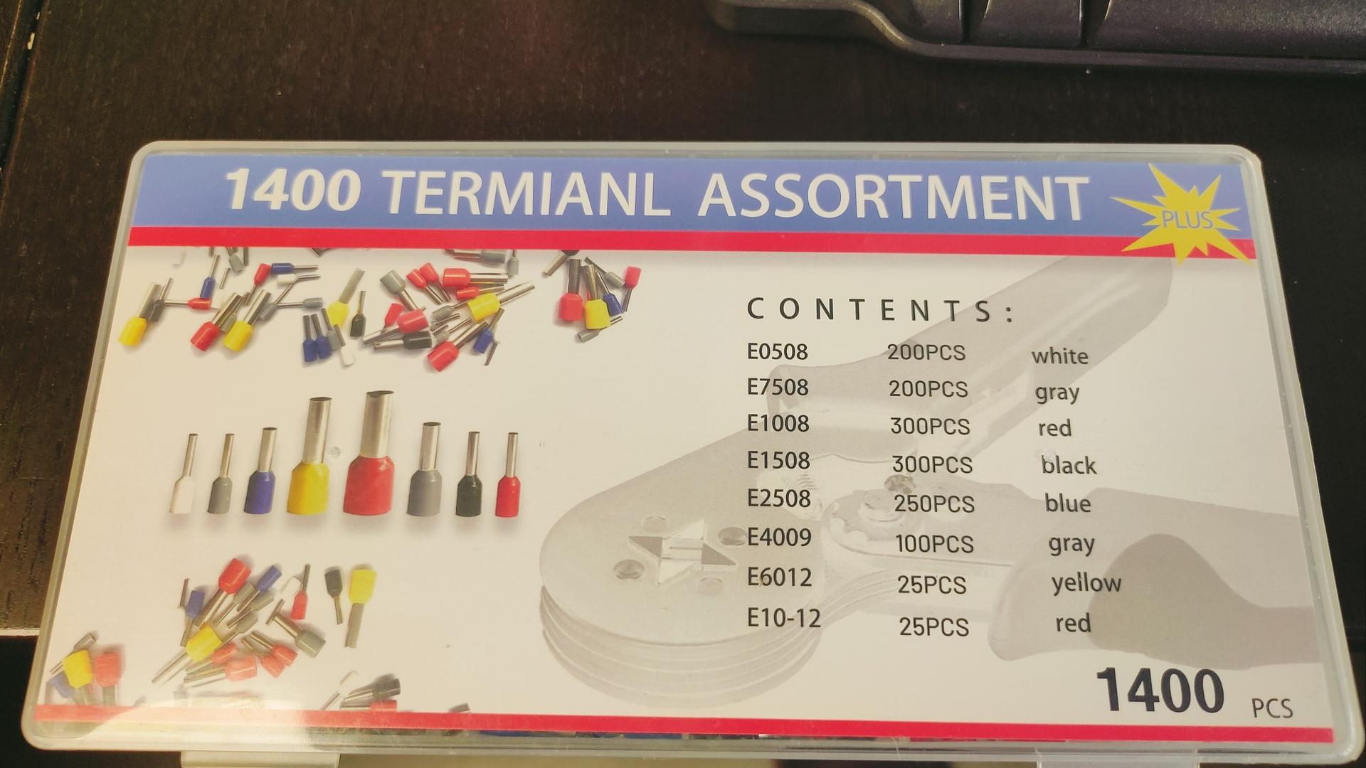
Funny text on box
What is a termianl assortment? LOL
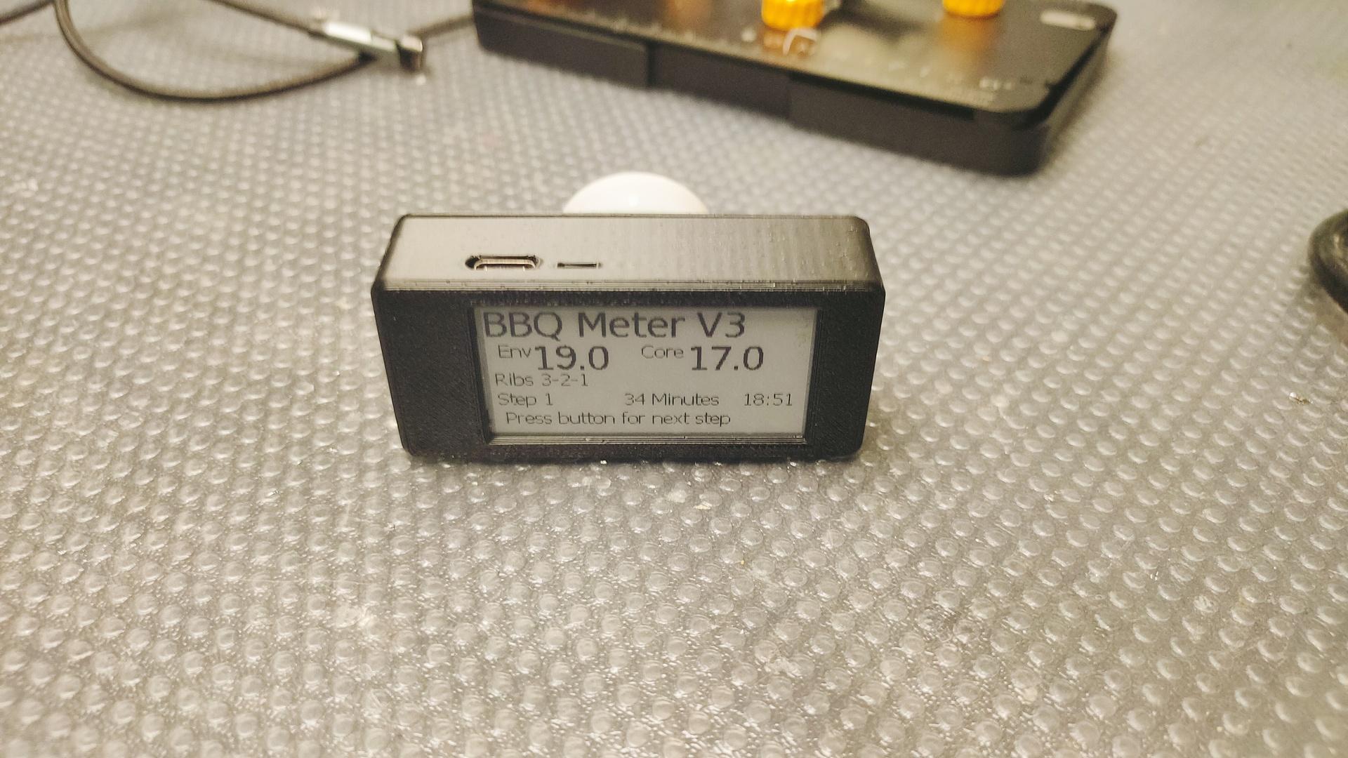
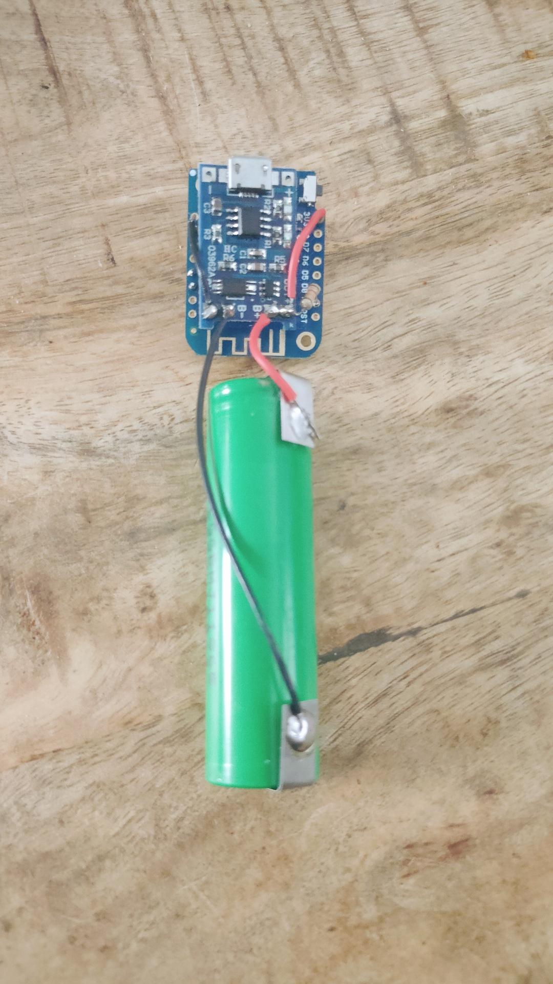
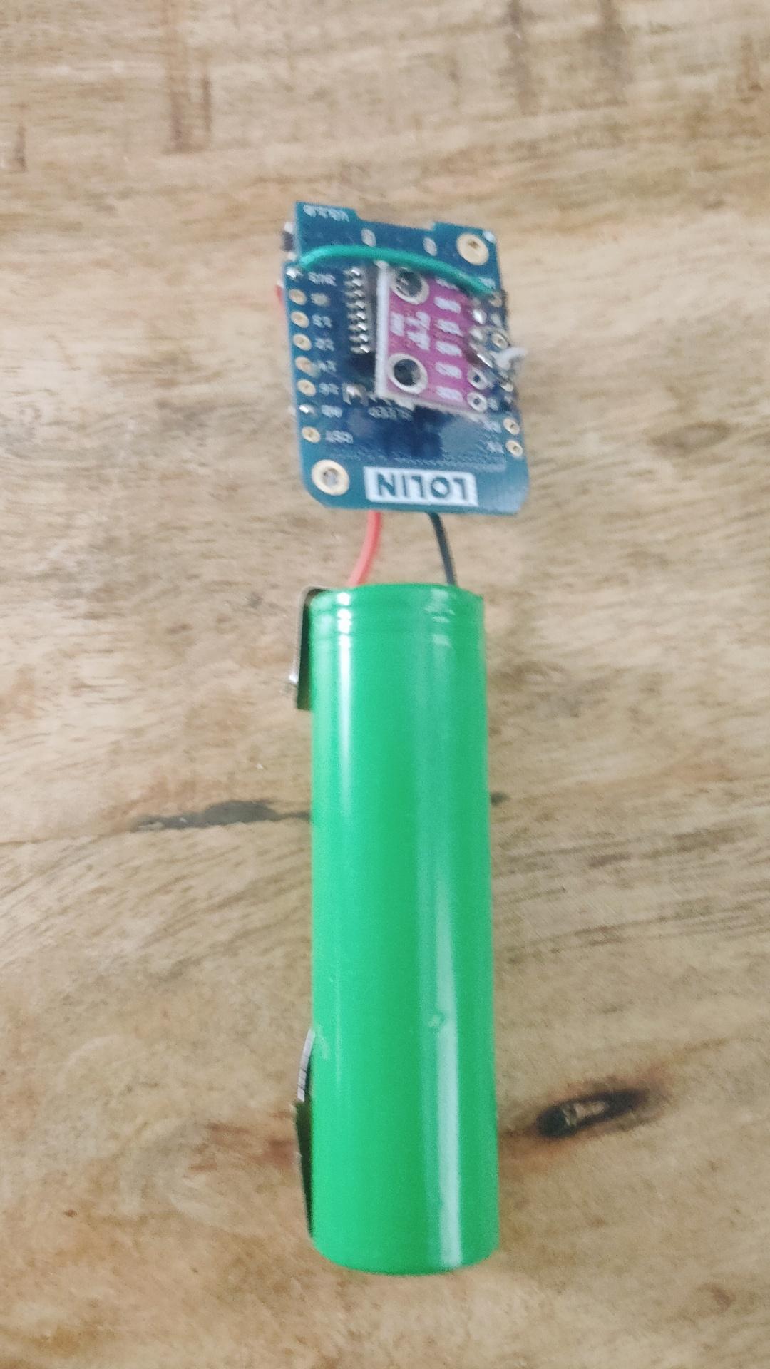
Wireless Temperature/Humidity sensor for ESPHome.
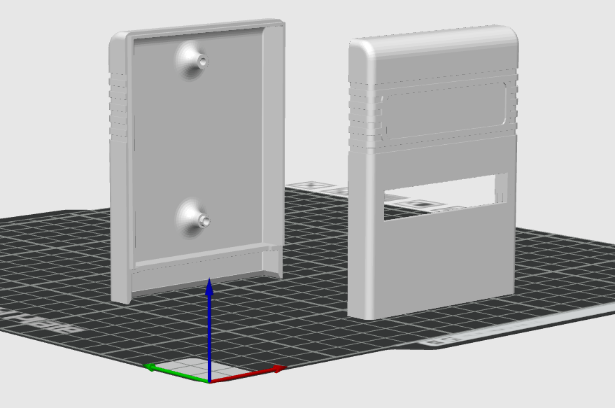
Wemos D1 mini with deep sleep, voltage monitoring using A0 line. BME280 Temperature/Humidity sensor. And a 18650 battery with TP4065 battery manager. Now 3D print a little case.
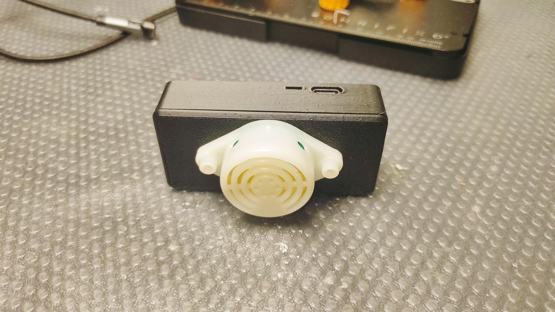
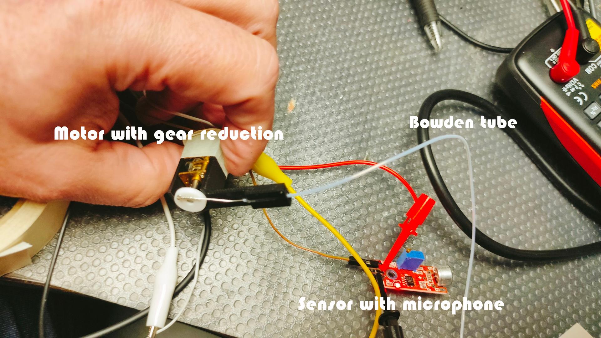
Using a bowden tube (PTFE tube 1mm) with a 3d printed holder. (ptfe is very smooth)
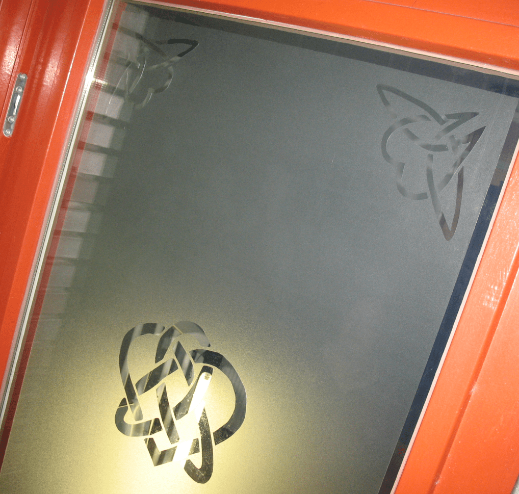
This is a test setup. I’ve removed arms and the flute on the bottom picture using AI. Then printed backpicture and top on sticky paper and stuck it on sturdy heavy paper.
I want to make a moving picture which moves our band members when there is sound (music). (Guitar, Harp, Bagpipes and Flute)
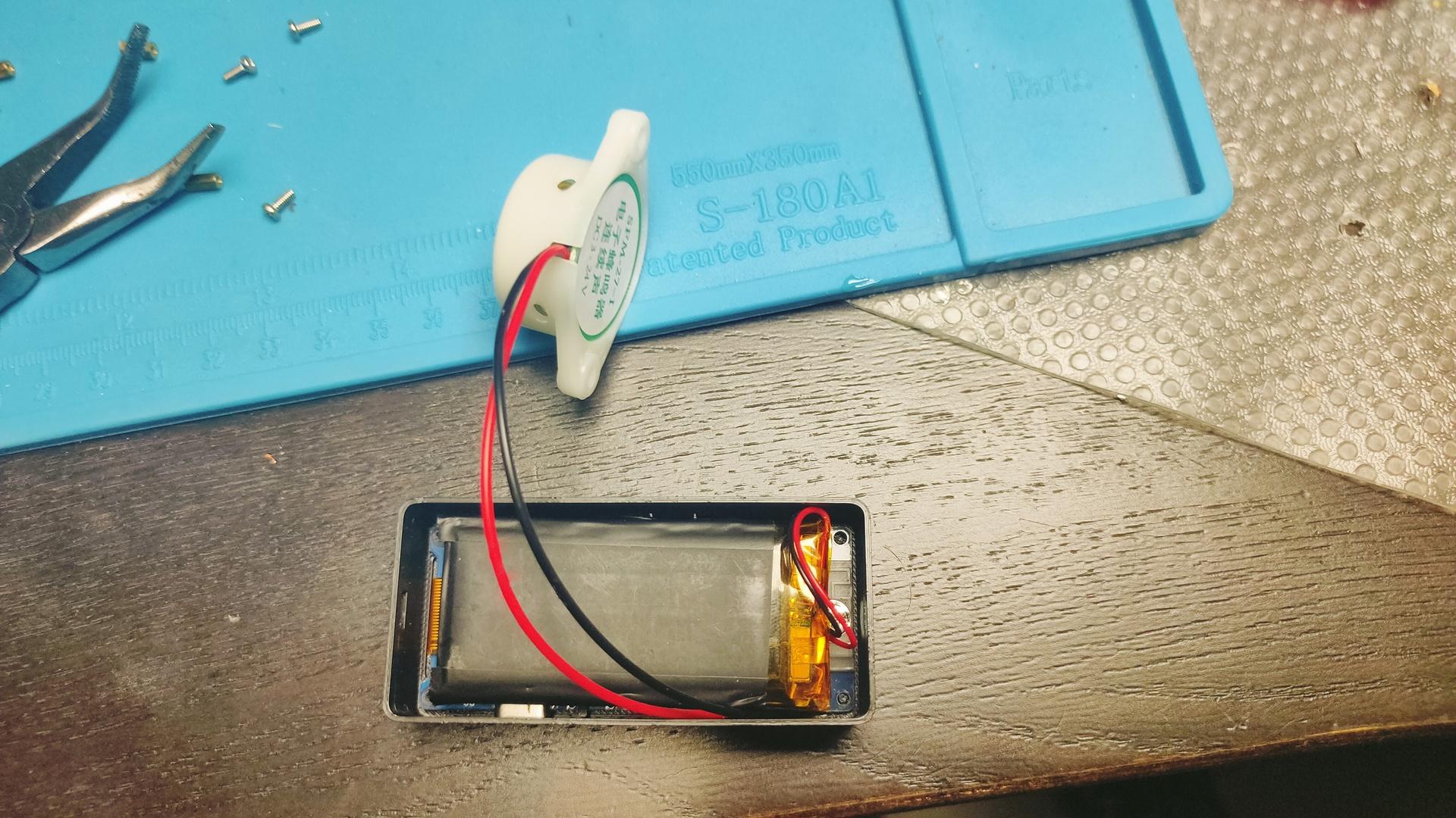
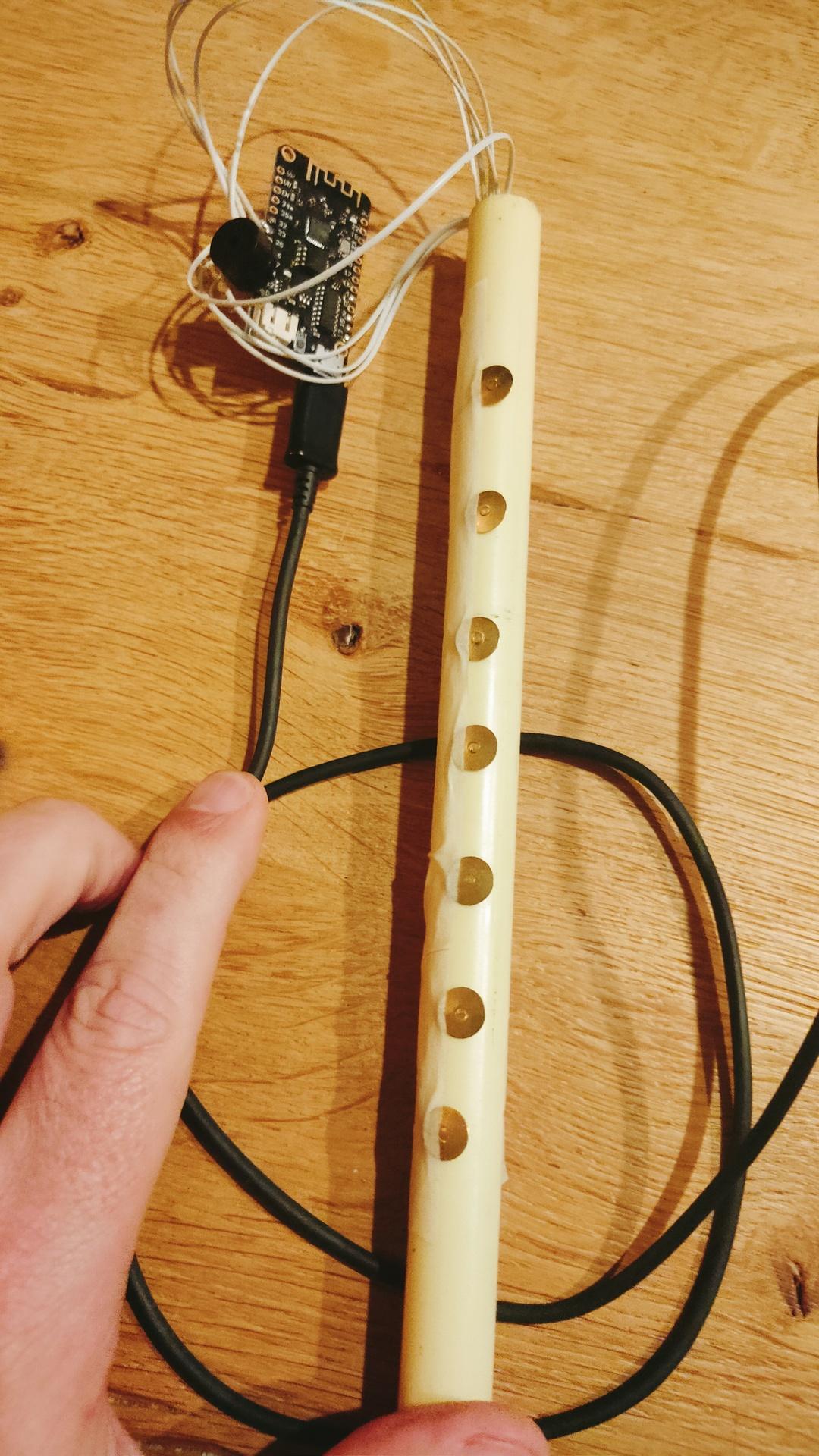
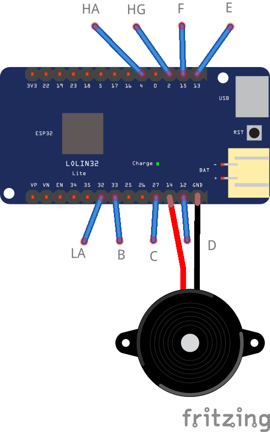
My proof of concept to build an electronic chanter for less than 4 euros.
It uses a Lolin32 Lite and a buzzer. (No libraries needed) (Some wires, thumbtacks and a PVC tube.)
I still have to glue the thumbtacks
Plays accidentals (false fingering) Vibrato Has serial console debugging Need other frequencies? Just edit the source.
CODE
int prevnote = 0;

// Note freq table
int ha = 880;
int hg = 783;
int fs = 739;
int f = 698;
int e = 659;
int d = 587;
int cs = 554;
int c = 523;
int b = 493;
int as = 466;
int la = 440;
int lg = 391;
int mute = 0;

// 8 Bits to note, luckly not 9 fingers :)
// 0 (00000000) = all fingers off = mute
// bottom hand top hand
//     0111 011
//             1
// 01110111 = 119 = E
// 255 (11111111) = all fingers on = lg
// below per 10 all 255 posibilities
// Look at position 175
// custom frequency to get vibrato on D
// using bottom hand middle finger.

int data[] = {
mute,hg,ha,fs,ha,hg,ha,e,ha,hg,ha,
f,ha,hg,ha,d,ha,hg,ha,fs,ha,
hg,ha,e,ha,hg,ha,f,ha,hg,ha,
c,ha,hg,ha,f,ha,hg,ha,e,ha,
hg,ha,f,ha,hg,ha,d,ha,hg,ha,
f,ha,hg,ha,e,ha,hg,ha,f,ha,
hg,ha,b,ha,hg,ha,f,ha,hg,ha,
e,ha,hg,ha,f,ha,hg,ha,d,ha,
hg,ha,f,ha,hg,ha,e,ha,hg,ha,
e,ha,hg,ha,c,ha,hg,ha,f,ha,
hg,ha,e,ha,hg,ha,f,ha,hg,ha,
d,ha,hg,ha,fs,ha,hg,ha,e,ha,
hg,ha,f,ha,hg,ha,la,ha,hg,ha,
f,ha,hg,ha,e,ha,hg,ha,f,ha,
hg,ha,d,ha,hg,ha,f,ha,hg,ha,
e,ha,hg,ha,f,ha,hg,ha,cs,ha,
hg,ha,f,ha,hg,ha,e,ha,hg,ha,
f,ha,hg,ha,580,ha,hg,ha,f,ha,
hg,ha,e,ha,hg,ha,f,ha,hg,ha,
as,ha,hg,ha,f,ha,hg,ha,e,ha,
hg,ha,f,ha,hg,ha,d,ha,hg,ha,
f,ha,hg,ha,e,ha,hg,ha,f,ha,
hg,ha,c,ha,hg,ha,fs,ha,hg,ha,
e,ha,hg,ha,f,ha,hg,ha,d,ha,
hg,ha,fs,ha,hg,ha,e,ha,hg,ha,
fs,ha,hg,ha,lg };

void setup() {
  pinMode(14, OUTPUT);

  Serial.begin(115200);
  delay(1000);
  }

void loop() {
  int t1=touchRead(4);
  int t2=touchRead(2);
  int t3=touchRead(15);
  int t4=touchRead(13);
  int t5=touchRead(12);
  int t6=touchRead(27);
  int t7=touchRead(33);
  int t8=touchRead(32);

int note = 0;

// Debug reading
//Serial.println(t1);
// My readings are near zero and above 50
// So I chose 30 (adjust when needed)

if ( t1 < 30) {
  bitSet(note, 0);
}
if ( t2 < 30) {
  bitSet(note, 1);
}
if ( t3 < 30) {
  bitSet(note, 2);
}
if ( t4 < 30) {
  bitSet(note, 3);
}
if ( t5 < 30) {
  bitSet(note, 4);
}
if ( t6 < 30) {
  bitSet(note, 5);
}
if ( t7 < 30) {
  bitSet(note, 6);
}
if ( t8 < 30) {
  bitSet(note, 7);
}

//Serial.println(note);
  if (note == 0 && note != prevnote) {
    noTone(14);
    prevnote = 0;
  }

if (note != prevnote) {
  tone(14,data[note]);
  // debug
  //Serial.print("Note number : ");
  //Serial.println(note);
  //Serial.print("Freq : ");
  //Serial.println(data[note]);

  prevnote = note;
  }
}
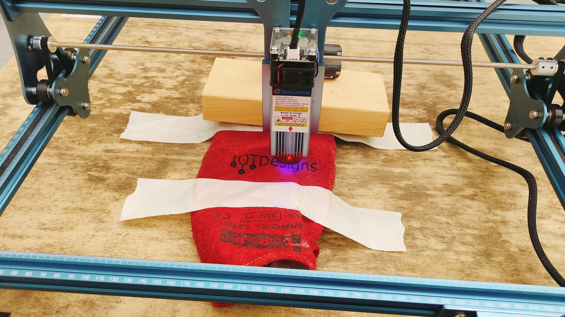
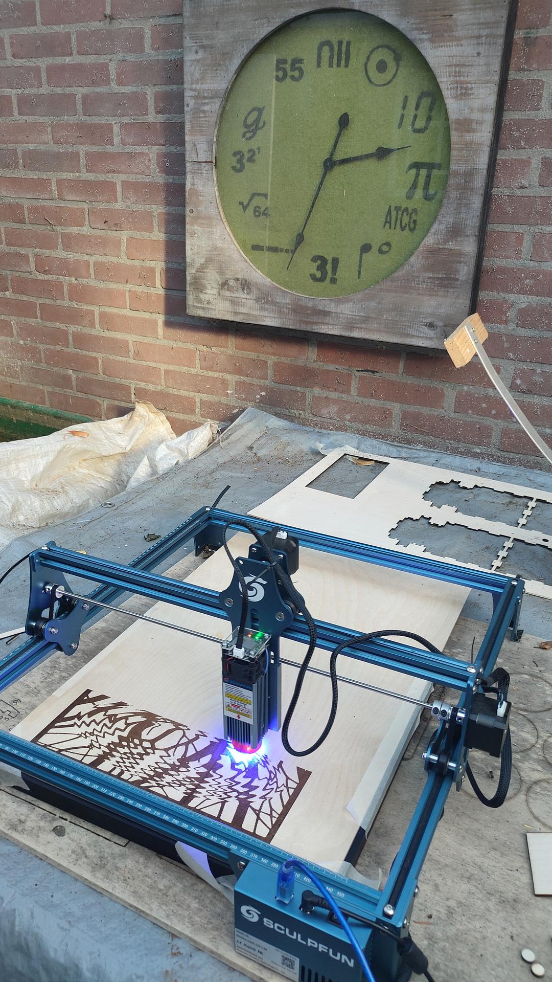
I’ve got a SculpFun Laser Cutter. I’m using this a lot … as lasercutter.
But you can also use a laser cutter as a Plotter or vinyl cutter!
Just remove the laser head, and replace it with a pen or knife! (360 swivel blade)
First : replace laserhead and make a controllable pen holder.
My Laser Cutter can be controlled using G-codes real-time. Example my etch a sketch. Now I just have to add a Z axis controller to control pen up/down.