Tag Archives: 6502

IRQ redirect for other programs

I’ve got a ROM in my 6502 which can load programs at $0200.
When running own programs i want to use IRQ’s, but my rom is also using IRQ routines.
So i was wondering if i could ‘hijack’ this IRQ for own program purposes.

So i’ve altered the rom to use a vector in userspace.

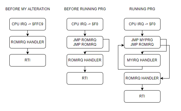
  • CPU starts, getting vector from FFFC
  • Goto $8000 main ROM program
  • Setting a jmp routine on zero page $F0
    • 4C C9 FF
    • 4C C9 FF ; second time, first one will redirect
  • Running my program on $0200
  • Change first jmp C9 FF to my own IRQ part
    • Changed jmp vectors
    • 4C 6E 02 ; jmp $026E (myprg)
    • 4C C9 FF ; jmp $FFC9 (rom)
  • Run rest of program

All seems fine and dandy … buzzer is sounding, but no blinky leds.
When flashing the rom with only my program, everything works ..
So whats going on? .. anyone?

00000000  78 a9 6e 85 f1 a9 02 85  f2 58 a9 ff 8d 03 50 8d  |x.n......X....P.| ; sei , lda #$6e, store $f1, lda #$02, store $f2 - so address $026e
00000010  02 50 a9 00 8d 01 50 8d  00 50 85 04 20 45 02 a9  |.P....P..P.. E..|
00000020  77 8d 04 50 a9 07 8d 05  50 20 2f 02 4c 29 02 38  |w..P....P /.L).8|
00000030  a5 00 e5 04 c9 19 90 0c  a9 40 4d 00 50 8d 00 50  |.........@M.P..P|
00000040  a5 00 85 04 60 a9 00 85  00 85 01 85 02 85 03 a9  |....`...........|
00000050  c0 8d 0b 50 a9 a0 8d 0e  50 a9 0e 8d 08 50 a9 27  |...P....P....P.'|
00000060  8d 09 50 a9 00 8d 04 50  8d 05 50 58 60 40 48 a9  |..P....P..PX`@H.| ; at $6e opcode 48 (pha) 
00000070  0e 8d 08 50 a9 27 8d 09  50 e6 00 d0 0a e6 01 d0  |...P.'..P.......|
00000080  06 e6 02 d0 02 e6 03 68  4c f3 00                 |.......hL..|

ROM parts

MYIRQ = $F0                                     ; Own IRQ vector <=================== my additions/alterations

; Below definitions for VIA 1 my loadable program uses VIA 2
PORTB = $6000                                   ; VIA port B 
PORTA = $6001                                   ; VIA port A
DDRB = $6002                                    ; Data Direction Register B
DDRA = $6003                                    ; Data Direction Register A

-------------8<------- snip

PROGRAM_LOCATION = $0200                        ; memory location for user programs

    .org $8000

main:                                           ; boot routine, first thing loaded
    ldx #$ff                                    ; initialize the stackpointer with 0xff
    txs

; ISR redirect code  <=================== my additions/alterations
    sei
    lda #$4C
    sta MYIRQ
    sta MYIRQ + 3
    lda #<ISR
    sta MYIRQ + 1
    sta MYIRQ + 4
    lda #>ISR
    sta MYIRQ + 2
    sta MYIRQ + 5
    cli

; End ISR redirect <=================== till here

; below this the standard rom routines

-------------8<------- snip
    .org $FFC9                                  ; as close as possible to the ROM's end

ISR:                                                  <====================== Whole ISR not my code
CURRENT_RAM_ADDRESS = Z0                        ; a RAM address handle for indirect writing
    pha
    tya
    pha
    lda ISR_FIRST_RUN                           ; check whether we are called for the first time
    bne .write_data                             ; if not, just continue writing
    lda #1                                      ; otherwise set the first time marker
    sta ISR_FIRST_RUN                           ; and return from the interrupt
    jmp .doneisr
.write_data:
    lda #$01                                    ; progressing state of loading operation
    sta LOADING_STATE                           ; so program_ram routine knows, data's still flowing
    lda PORTB                                   ; load serial data byte
    ldy #0
    sta (CURRENT_RAM_ADDRESS),Y                 ; store byte at current RAM location
                                                ; increase the 16bit RAM location
    inc CURRENT_RAM_ADDRESS_L
    bne .doneisr
    inc CURRENT_RAM_ADDRESS_H
.doneisr
    pla                                         ; restore Y
    tay
    pla                                         ; restore A
    rti

    .org $fffc
    .word main                                  ; Main ROM program
    .word MYIRQ                                 ; Redirect to OWN irq vector <=================== my additions/alterations

RAM Program

; Second VIA stuff
PORTB = $5000
PORTA = $5001
DDRB = $5002
DDRA = $5003
;------------------8<-------------

; Vector pointer on zero page
MYIRQ = $F0 

ticks = $00 ; 4 Bytes
toggle_time = $04 ; 1 Byte

    .org $0200

start:
; IRQ REDIRECT
    sei               ; irq masked
    lda #<irq         ; get low byte IRQ routine address 
    sta MYIRQ + 1     ; store at $F1

    lda #>irq         ; get high part of address
    sta MYIRQ + 2     ; store at $F2
    cli               ; irq enabled
; IRQ END REDIRECT

; init of program part
    lda #%11111111
    sta DDRA
    sta DDRB
        lda #$00
    sta PORTA
    sta PORTB
    sta toggle_time
    jsr init_timer
    lda #$77
    sta T1CL
    lda #$07
    sta T1CH

loop:                       ; loop 
    jsr update_led          ; update led routine
    jmp loop

update_led:
    sec
    lda ticks
    sbc toggle_time
    cmp #25
    bcc exit_update_led
    ; Toggle led
    lda #%01000000
    eor PORTB
    sta PORTB
    lda ticks
    sta toggle_time
exit_update_led:
    rts

;-----------------------------8<------------- snip

irq:
    pha
    lda #$0e
    sta T2CL
    lda #$27
    sta T2CH
    inc ticks
    bne end_irq
    inc ticks + 1
    bne end_irq
    inc ticks + 2
    bne end_irq
    inc ticks + 3
end_irq:
    pla
    jmp MYIRQ + 3           ; jmp to vector which points to ROM routine ; should be $FFC9

6502 update

  • New amplifier part using a LM386
  • Buzzer and led on VIA 2, blinky and sound timed by the internal timers of the 6522
  • ACIA testing still going on, writing software
  • Mini matrix keyboard removed, and used the temporary cursor buttons for the test with a rom which allows for a 8bits upload method using a arduino and the 6522. (I’m working on the big keyboard)

Work in progress code

PORT2B = $5000 		; VIA PORTB
PORT2A = $5001 		; VIA PORTA
DDR2B = $5002  		; Data direction register
DDR2A = $5003  		; Data direction register

PORTB = $6000 		; display
PORTA = $6001 		; control display + matrix keyboard
DDRB = $6002  		; data direction register
DDRA = $6003  		; data direction register
SID = $7000   		; sid base address

E  = %10000000		; enable bit
RW = %01000000		; RW bit 
RS = %00100000		; Register Select bit 
HOME = %00000010 	; VIA PORTB HOME command
DADDR = %00010000 	; VIA DADDRESS

LINENO = $0200		; temp address linenumber (move to other location)
NEXTLINE = 40		; 2x16 Chars but internally 40


  .org $8000

reset:
  ldx #$ff
  txs		; reset stack

; ###################################################
; #                 DISPLAY CONTROL                 #
; ###################################################
; VIA Setup

  lda #%11111111 	; Set all pins on port B to output
  sta DDRB
  lda #%11100000 	; Set top 3 pins on port A to output
  sta DDRA

; DISPLAY Setup
  lda #%00111000 	; Set 8-bit mode; 2-line display; 5x8 font
  jsr lcd_instruction
  lda #%00001110 	; Display on; cursor on; blink off
  jsr lcd_instruction
  lda #%00000110 	; Increment and shift cursor; don't shift display
  jsr lcd_instruction
  lda #$00000001 	; Clear display
  jsr lcd_instruction

; ###################################################
; #             PRINT MESSAGE LINE NO 0             #
; ###################################################
  lda #0  		; set line number
  sta LINENO      	; store for subroutine
  jsr gotoline		; move cursor

  ldx #0		; message index pointer
print:
  lda message0,x 	; start of message
  beq nextprint      	; stop when null in message (asciiz <- Zero padded)
  jsr print_char	; print char
  inx			; incr index
  jmp print		; resume print
; ###################################################
; #             PRINT MESSAGE LINE NO 1             #
; ###################################################
nextprint:
  lda #1  		; set line number
  sta LINENO      	; store
  jsr gotoline
  ldx #0  		; index pointer                 
print2:
  lda message1,x  	; absolute address message + x in A
  beq sidsound        	; if x is 0, end of message     
  jsr print_char  	; jump subroutine
  inx             	; increment x
  jmp print2      	; loop print2


; ###################################################
; #             SID SOUND                           #
; ###################################################
sidsound:
  lda #0		
  sta SID+$5		; attack/decay duration
  	
  lda #250
  sta SID+$6		; sustain level/release duration
  	
  lda #$95		; frequency voice 1 low byte
  sta SID+$0
  	
  lda #$44		; frequency voice 1 high byte
  sta SID+$1
  
  lda #%00100001	; sawtooth + gate
  sta SID+$4		; control register voice 1
  
  lda #$0f		; filter mode and volume (bits 3-0 main volume)
  sta SID+$18		; filter mode and volume


; ###################################################
; #             2ND VIA                             #
; ###################################################
  lda #%11111111 	; set port A output
  sta DDR2A

  lda #%11111111	; all ones!
  sta PORT2A
; ###################################################
  lda #%11111111 	; set port A output
  sta DDR2A

  lda #%11111111	; all ones!
  sta PORT2A


; ###################################################
; #             MAIN PROGRAM LOOP                   #
; ###################################################
loop:
  jmp loop
;                   1234567812345678
message0: .asciiz  "VIA 1,2 SID TEST"
message1: .asciiz  "   FASH  2022   "

; ###################################################
; #             ONLY SUBROUTINES                    #
; ###################################################

; ###################################################
; #             Subroutine gotoline                 #
; # Moves character placement position on display   #
; # Needs : $LINENO ADDRESS                         #
; # Exit values : -                                 #
; # Destroys registers: -                           #
; ###################################################

gotoline:
  pha                             ; store a
  txa
  pha                             ; store x
  ldx LINENO
  lda #HOME                       ; cursor down
  jsr lcd_instruction
  lda #$80
nextline:
  ldx LINENO
  cpx #00
  beq endnextlines
loopline:
  adc #40
  jsr lcd_instruction
  dex
  stx LINENO
  jmp nextline
endnextlines:
  pla                             ; pop a
  tax                             ; a to x
  pla                             ; pop a
  rts


; ###################################################
; #             LCD SUBROUTINES                     #
; ###################################################
lcd_wait:
  pha
  lda #%00000000  ; Port B is input
  sta DDRB
lcdbusy:
  lda #RW
  sta PORTA
  lda #(RW | E)
  sta PORTA
  lda PORTB
  and #%10000000
  bne lcdbusy
  lda #RW
  sta PORTA
  lda #%11111111  ; Port B is output
  sta DDRB
  pla
  rts
lcd_instruction:
  jsr lcd_wait
  sta PORTB
  lda #0         ; Clear RS/RW/E bits
  sta PORTA
  lda #E         ; Set E bit to send instruction
  sta PORTA
  lda #0         ; Clear RS/RW/E bits
  sta PORTA
  rts
print_char:
  jsr lcd_wait
  sta PORTB
  lda #RS         ; Set RS; Clear RW/E bits
  sta PORTA
  lda #(RS | E)   ; Set E bit to send instruction
  sta PORTA
  lda #RS         ; Clear E bits
  sta PORTA
  rts

nmi:
  rti

irq:
  rti

  .org $fffa
  .word nmi
  .word reset
  .word irq
;  .word $0000

6502 news

Divers new additions to the 6502 project

Above is my design for a hex keyboard to enter opcodes in hex using a simple monitor program.
i used a 74ls922 which can decode a 4×4 matrix. I’d rather had a 74ls723 which can encode 20 keys.

Nowhere to be found. So i have to think of a new plan.

Now it is configured as follows:

CDEF
89AB
4567
0123

When pressing the alternate key

addr
(to implement)
run
(1/2 implemented)
reset
(to implement)
step instruction
(to implement)
memory next
memory previous
PCB design for matrix hexboard with place for notes

Meanwhile i’ve ordered new keys (the ones i’ve been using for my photomanager project and wnat to have a setup like this:

??addrrunreset
CDEF?
89ABstep
4567mem next
0123mem prev

When you want to show the status of busses and alike, you can’t use a led and restistor directly on the bus, it will require too much current.
So i’ve been using below schematic which uses a darlington array.

Now i can display databus, address bus and i’ve been using this for address decoding logic and hex keyboard.

I’ve implemented a second VIA chip, and ordered components to amplify the SID sound part

6502 progress

Added second VIA chip. (For hex keyboard)

Skipped the sound setups with simple components or the Yamaha chip. Straight to the commodore SID chip. Added a amplifier and a speaker.

Added ROM functions for line printing. Picture with 2 lines, and my name in Japanese

Now I have to wait for components. I’ve made a simulation for a address decoder.

Rest I’ve put in previous posts as updates.

Meanwhile testing 6502 apps on Android


Kicad – Power-on-reset

UPDATE: 20220728 Added POC

The workshop at MCH2022 gave me the idea to make my next PCB not at home, but professionally.

I’m planning to make my 6502 on modular PCB’s when i’ve got the base part working.
( I probably will only make THT (Though Hole Technology) boards instead of smd )
So i’ll probably end up making a few boards, namely:

  • Power on reset
  • Clock module
  • Interconnect with arduino
  • CPU, memory and ROM
  • Display
  • 6522 Via
  • SID chip
  • Hex keyboard

This power-on reset is based on the original C64 part to reset the CPU when you power the machine on. With my 6502 i have to manually push reset to start booting.
(The CPU starts in a unknown state when you power it up, it needs a reset)

Schematic
PCB design
Rendering

Working POC

MCH 2022

Back from the hackers event “May Contain Hackers”

MCH2022 is a nonprofit outdoor hacker camp taking place in Zeewolde, the Netherlands, July 22 to 26 2022. The event is organized for and by volunteers from the worldwide hacker community.

Knowledge sharing, technological advancement, experimentation, connecting with your hacker peers and hacking are some of the core values of this event.

MCH2022 is the successor of a string of similar events happening every four years since 1989.
These are GHPHEUHIPHALWTHHAROHM and SHA.

I’ve bin to several of these big events. Besides these big events are many different smaller events (wannull, ne2000 etc).

First one i’ve been was HIP97. I went with Bigred at that time.
I had to get the tickets at that time, he didn’t had a handle at that time. It was Monique who came up with his new nick.

After HIP97 there was HAL2001 WTH2005 and OHM2013 which i was present.
HAL2001 the whole ICEcrew was present, WTH a part of them, OHM a few and i was with a few PRUTS friends.

Now i was with my girlfriend, AND with Bigred again!
Loads of fun and memories. Had not seen Bigred since a inbetween hacker party at my place.
So ’97 and now ’22 .. jeez 25 years!

So MCH, it was great again.
Loads of stuff to do and to see.
Weather was … okay. Two days where really hot, one day some light rain but a load of wind. Our neighbours tent collapsed, beer tents where reenforced.
First campsite with a supermarket!
Music stage was awesome, lasers and fire!

I went to a lot of talks, even my girlfriend found some she was interested in.

This was the last time i’ve brought my “Windows free zone tape”
This big roll of tape was used on many occasions.
I got this roll somewhere < 2000, I did a search but couldn’t find anything mentioning it on the web. Maybe some archive.org entry?

  • Starting a Home Computer Museum (which i almost did in the past)
  • streaming 360 video (going to try this with my Vuze XR Camera)
  • Non-Euclidean Doom: what happens to a game when pi is not 3.14159…
    (Really enjoyed this one)
  • Hacking the genome: how does it work, and should we?
  • And more

Besides the talks i’ve done some workshops:

  • Micropython on the badge (see my other post)
  • Kicad – PCB designing

Meanwhile we where looking at all the villages and hackerspaces. Loads of interesting people to meet. Like our neighbour two tents futher, he was also a home-brewer, and he brought a minifridge with beer taps connected to it.

When back at our tent or Bigreds Campervan, we talked about differences now and then. New technology, what we’ve been upto in the last years and tinkering, loads of tinkering.

I’ve brough a big plastic container with .. ehh “things to do ….”

  • My 6502, bigred helped me debugging the 16*2 display.
    (Luckily his campervan was packed with electronics!)
    We cannibalized one of his projects for a display, and re-flashed his eeprom programming arduino to test my display. ( The arduino i had to reflash later to program a rom he had given me for my 6502. )
    Other toys he gave me: Print for the programmer, and a C64 Cartridge print for Exrom and Game.
  • Mini C64 with a little screen and raspberry zero.
  • 5050 ledstrip (didn’t had time to reprogram this for our mood-light)
  • Handheld gamehat: Bigred found some old games he played when he was young
  • Mikrotik router, because i wanted to make a dmz for my girlfriends laptop. (MS)
  • Playing around with my Vuze XR camera
  • Huskycam, which i’m planning to use on a racetrack
  • DVB-T DAB FM Stick, got some hints and tips from Bigred.
    (Note to myself … fix the antenna!)
  • My Arduino touch bagpipe player with i2c
  • The wifi deauther, which has a display which i wanted to use to make a programmable clock for my 6502. Using a rotary encoder and the display to control the speed in Hz.
  • I spend many hours playing with the Badge and Kicad

Wrote some 6502 assembly, arduino sketches, php, bash and micropython.

While playing around with the badge i got some things working easily.
Spinning logo and blinky leds.
Next goal to achieve was, to get the gyroscope to control the angle of spinning.
Most of the code worked, but the gyro values stayed zero!
(After many hours …. you have to start/enable the chip/measurements on the bno055 first! .. duh! )

I didn’t had my dev directory from my main battlestation synced in my nextcloud, so changing things for the 6502 was a b*tch.
Used vasm and acme to generate a bin file to use to fill the rom.
Didn’t like the eeprom programmer program, because i could not easily check the rom contents.
Have to look into that later on.

While learning to use Kicad, which i only had been using to draw schematics (besides fritzing) , i learned to create a pcb.
Which gave me the idea to make a print for the power-on-reset for the 6502. Which is going to be the first PCB by ordering, instead of the old skool messing around with DIY print making. (see next post)

….. Oh, why my display was not working?
I even connected my 8bit logic analyzer to the pins of the display.

Everything was correct.
But i didn’t use a variable resistor for the contrast. Just a simple resistor i could find. Luckily … bigreds stash.
All those hours debugging, all for one resistor!
(I have to mention, we had a suspicion halfway. But it was too hot and we where too lazy to go to Bigred’s campervan, to get a potentiometer. )

Goodies from Bigred

DIY 6502 – VIC (Versatile Interface Adapter)

65c22 connected, new data, and address-bus ribboncables!

First led on Register B blinking!

Notes:
Temporary display wil be 2×16 Chars.
Ram in place, but not connected (is emulated by the Arduino Mega at the moment)
Rom is somewhere halfway the atlantic ocean .. still waiting on that one.
Ben Eatons clock module is disconnected, i’m using the Arduino as programmable clock right now.
(There wil be a little display and a rotary encoder to set clock speed.)

lda #$ff ; all bits
sta $6002 ; set direction (out) for B register
lda #$80 ; set 1 bit
sta $6000 ; set register B
lda #$00 ; reset bit
sta $6000 ; set register B
jmp $8005 ; jmp to bit set part