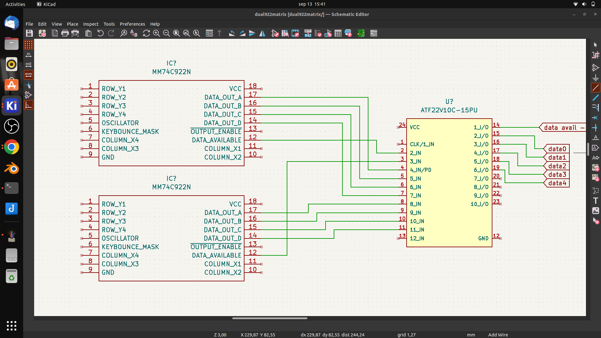
In this case designed for my 6502, but it is a generic setup.
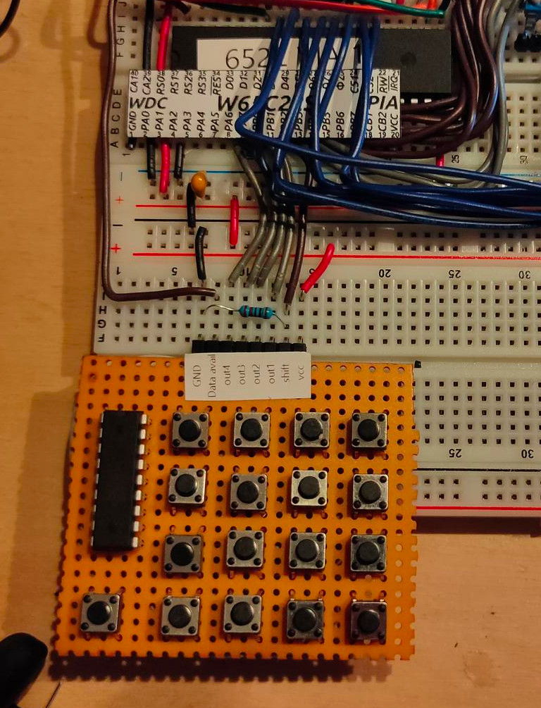
I it just a dual 16key matrix decoder merged together. You can probably use this with raspberries, arduinos etc.
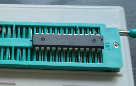
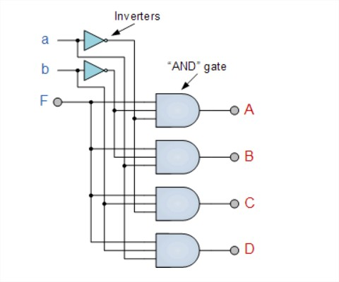
I wanted to use 74C923 but these are nowhere to be found. And even then, the number of keys wil be 20. So i am tying together two 74C922 using some logic in a PLD.
First draft
It wil be something like above. Using the data availabe signal i can combine both 16key matrixes. (In theory .. it is all untested)
Another blender project i’m planning to do this week is a movie displaying my logo to overlay on my videos. So i have to render a transparent movie for this.
Howto:
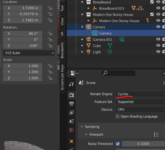
Open a scene, i took the liberty to get one from blenderkit.
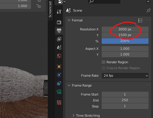
Change output to cycles, eevee doesn’t work
Make x/y large enough in output tab. X = 2 * Y !
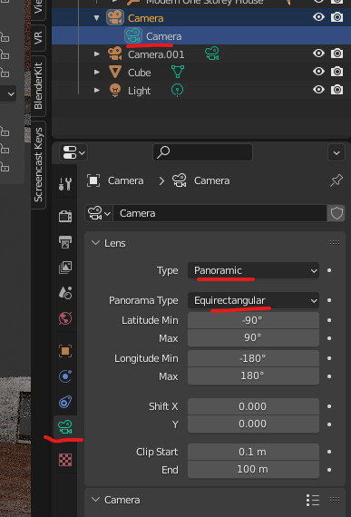
Next select your camera, and open camera tab
Change Type to panoramic and then you can change panorama type to Equirectangular
Position your camera and hit F12, it wil take a long time!
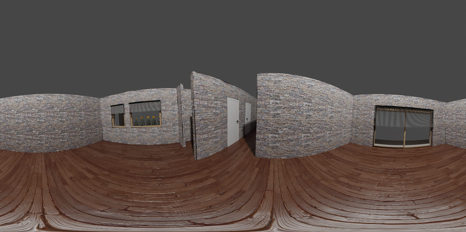
You get something like this
Use a proper plugin for your website, or view with your VR glasses!
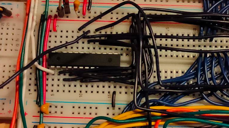
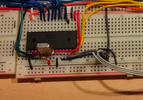
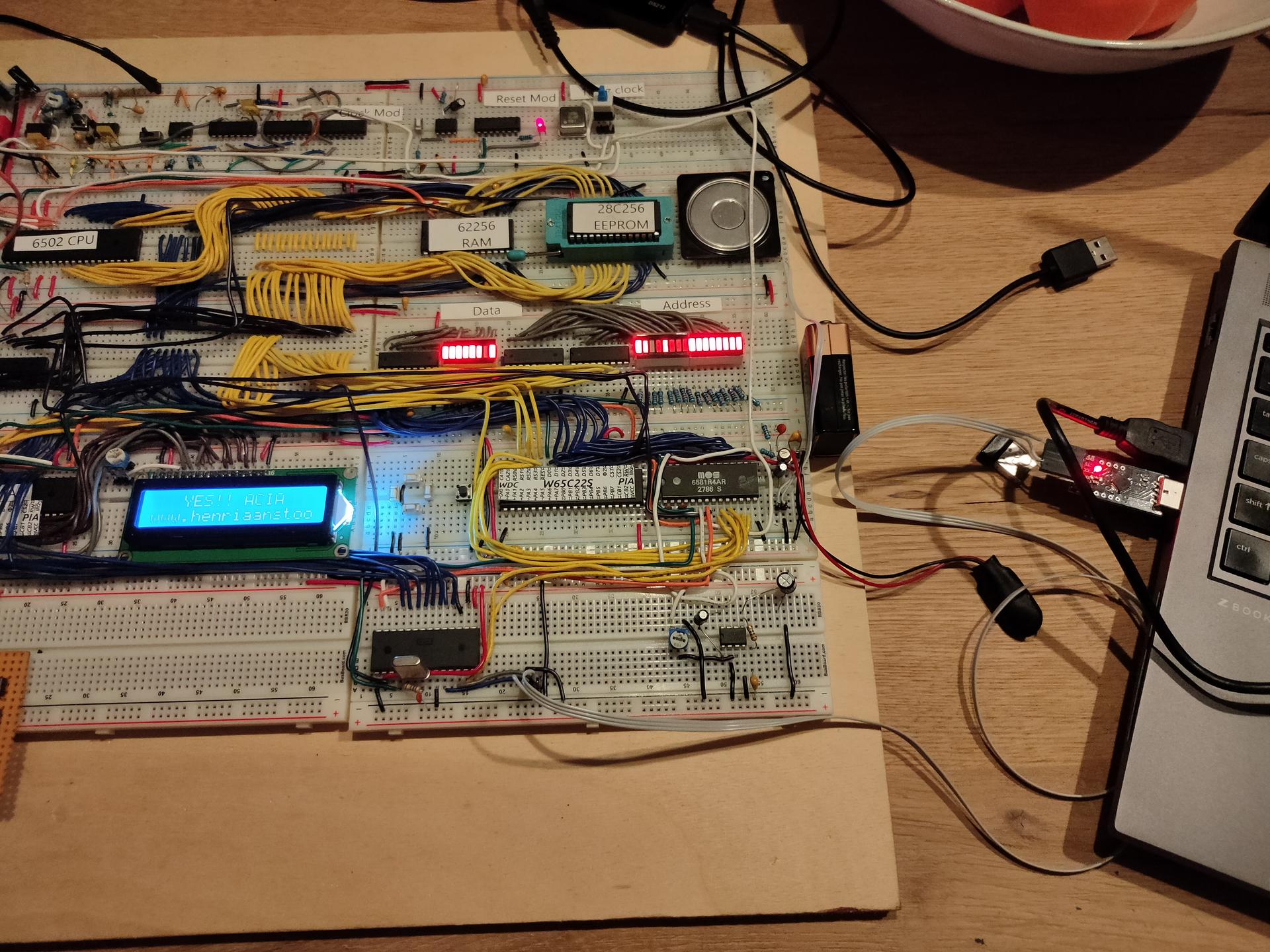
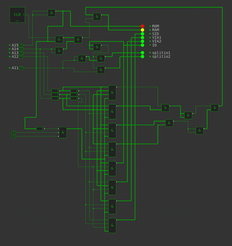
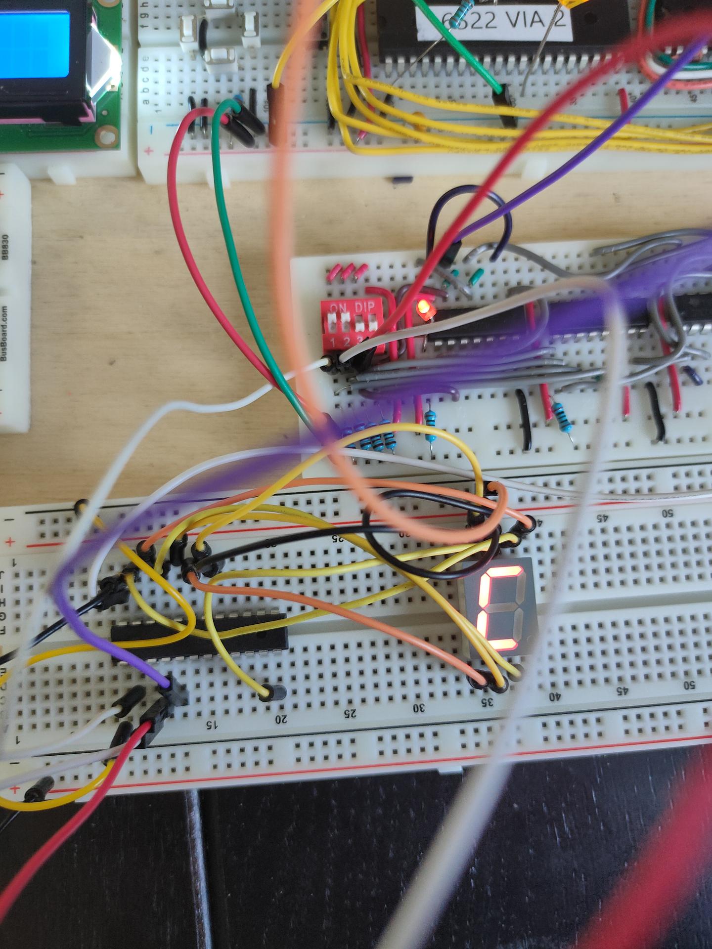
New address decoder in place! Connected RAM/ROM/SID/VIA1/VIA2 and ACIA
ROM
8000-FFFF
SID
7000-700F (sound)
VIA1
6000-60xx (Hex key matrix)
ACIA
6800-68xx (serial)
VIA2
5000-50xx (led test at the moment)
RAM
0000-3FFF
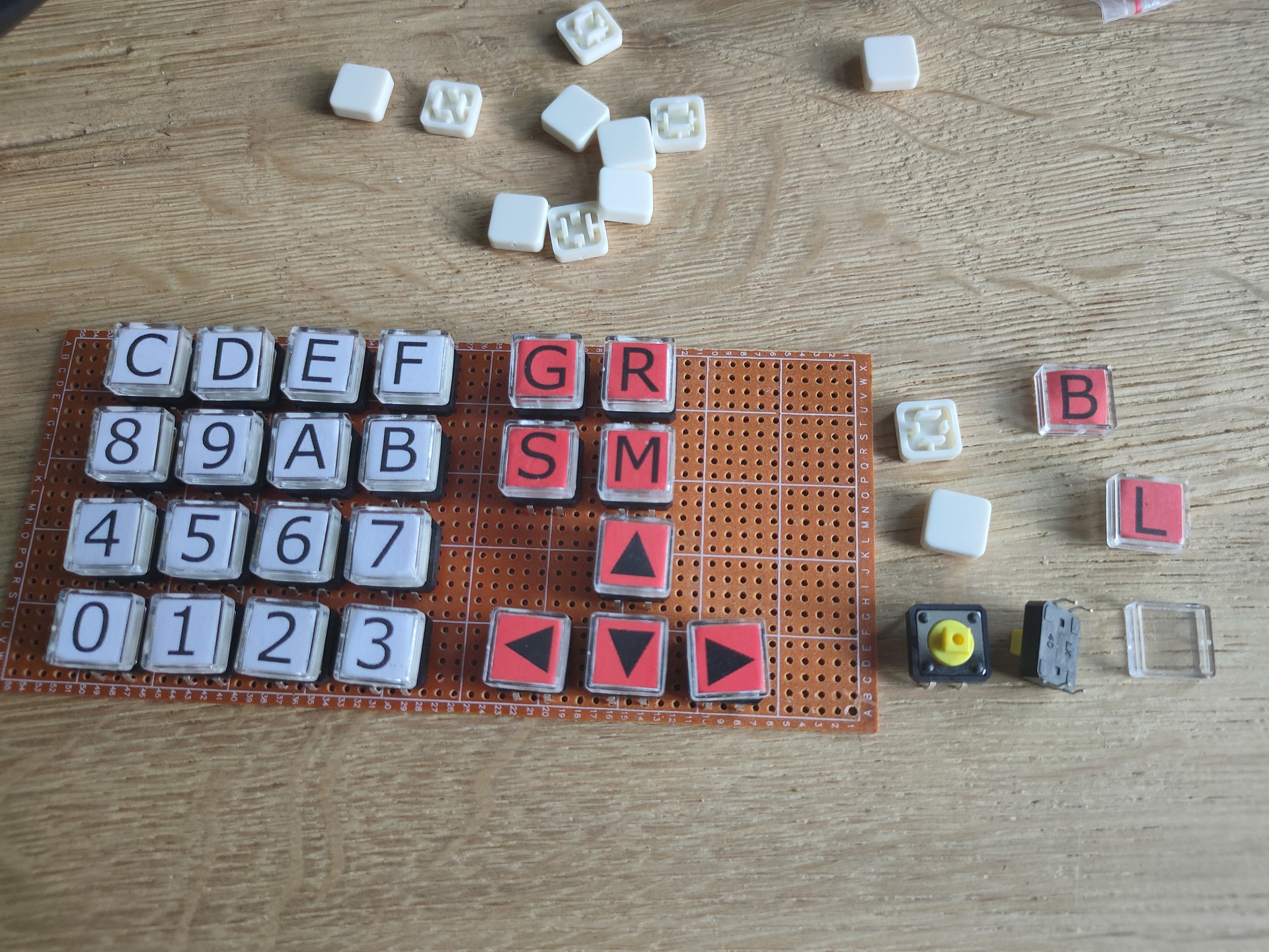
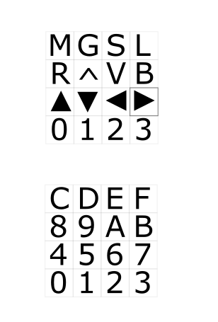
To plan: Bigger maxtrix keyboard and other displays
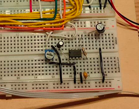
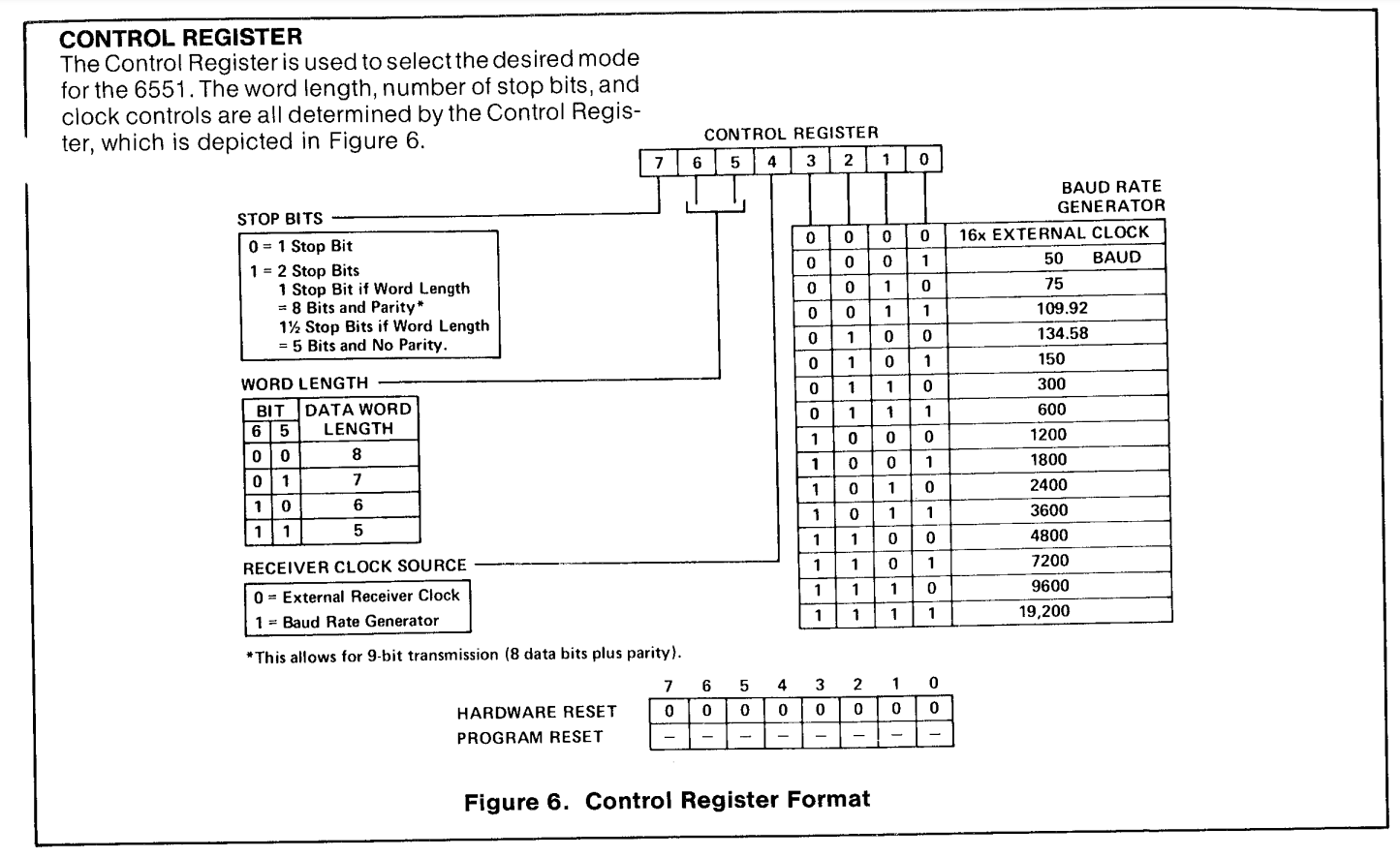
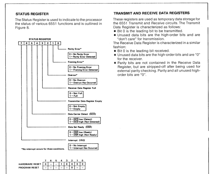
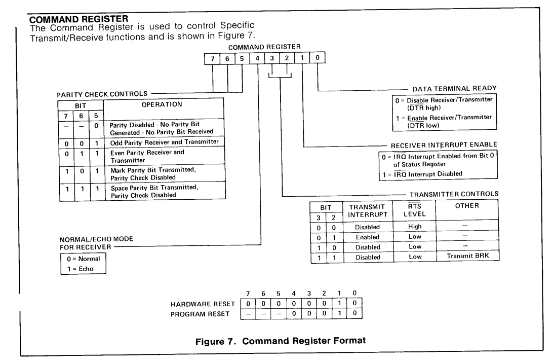
ACIA 6551
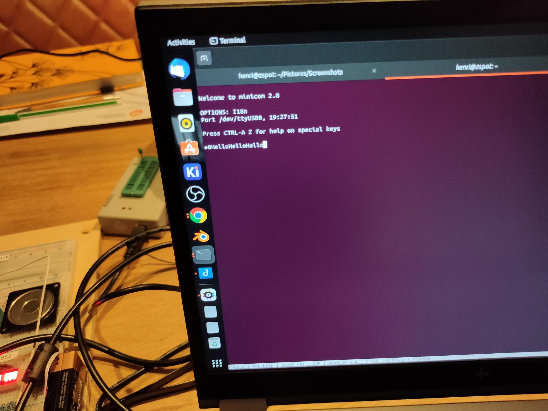
Got a serial connection working between the 6502 and my linux machine!
3 line serial – no hardware handshake
At the moment when a reset occurs , hello is being printed. Text typed in the minicom terminal, is echo-ed back and displayed on the LCD display.
Things learned: Do not trust internet schematics blindly!
The crystal used for the ACIA (pin 6/7 1.8432Mhz needs a 1M ohm resistor parallel over the crystal, and a 30nF capacitor from pin 7 to GND
When using a terminal emulator, and using 3 wires. Disable hardware handshake.
Keyboard rewired.
What didn´t work as planned:
New amplifier schematic for the SID. There is too much noise.
Amplifier with a LM628
Bought a dual power supply (5V and 12V). But this one has a lot of signal noise on the SID part and even my battlestation speakers!
LED test 2nd via
PORTB = $5000 ; VIA PORTB
PORTA = $5001 ; VIA PORTA
DDRB = $5002  ; Data direction register
DDRA = $5003  ; Data direction register

LED  = %10000000

	.org $8000

reset:

	lda #%11100000 ; Set top 3 pins on port A to output
	sta DDRA

	lda LED
	sta PORTA

loop:		; done loop until doomsday
	jmp loop

irq:
nmi:
	.org $fffa
	.word nmi
	.word reset
	.word irq
ACIA part
ACIA_RX = $6800
ACIA_TX = $6800
ACIA_STATUS = $6801
ACIA_COMMAND = $6802
ACIA_CONTROL = $6803

    lda #$00
    sta ACIA_STATUS
    lda #$0b
    sta ACIA_COMMAND
    lda #$1f
    sta ACIA_CONTROL
I was using zevv’s bucklespring way back since he was beta testing. https://github.com/zevv/bucklespring
Also cool-retro-term, i used whenever i felt nostalgic.
But both at the same time, how much fun is that!
(Both newly installed on my laptop, which i had to reinstall, because i f*cked it up beyond repair. installing openxr stuff. OpenXR is an open, royalty-free standard for access to virtual reality and augmented reality platforms and devices. )
The ATF22V10 is a Programmable Logic Device. This means you can program the logic in the chip.
Internally it looks like a big matrix of connections which you can program to connect/disconnect from certain logic.
It has just a bunch of inputs/outputs
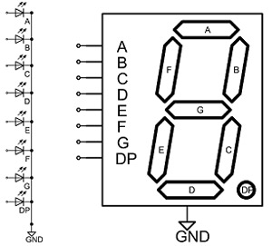
So if we want to have a 7 Segment decoder (you can easily buy a BCD decoder .. but these only work for displaying 0-9 and not 0-9A-F for displaying HEX numbers)
7 Segment display
Binary IN
7 Segment decoded
Displays
D C B A
A B C D E F G
0 0 0 0
1 1 1 1 1 1 0
0
0 0 0 1
0 1 1 0 0 0 0
1
0 0 1 0
1 1 0 1 1 0 1
2
0 0 1 1
1 1 1 1 0 0 1
3
0 1 0 0
0 1 1 0 0 1 1
4
0 1 0 1
1 0 1 1 0 1 1
5
0 1 1 0
1 0 1 1 1 1 1
6
0 1 1 1
1 1 1 0 0 0 0
7
1 0 0 0
1 1 1 1 1 1 1
8
1 0 0 1
1 1 1 1 0 1 1
9
1 0 1 0
1 1 1 0 1 1 1
A
1 0 1 1
0 0 1 1 1 1 1
B
1 1 0 0
1 0 0 1 1 1 0
C
1 1 0 1
0 1 1 1 1 0 1
D
1 1 1 0
1 0 0 1 1 1 1
E
1 1 1 1
1 0 0 0 1 1 1
F
Now we see that segment A is 1 in the case of (0,2,3,5,6,7,8,9,A,C,E,F)
When programming the PLD we can write that as: (note / means inverted a plus is OR, and * is AND) So A is 0 in case of input being (1,4,B,D)
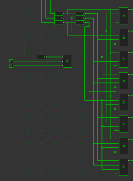
Made a simulation of my new address decoder. It uses a 74LS138 and a bunch of NAND gates. You can safe using 4 NAND gates if you are not going to use split IO
Address
8000-FFFF
ROM
ROM
7000-7FFF
Sound chip
SID
6000-6FFF
Display + cursor
VIA1
5000-5FFF
Keymatrix
VIA2
4800-4FFF
split io
IO
4000-47FF
split io
IO – ACIA
0000-3FFF
Uses clock
RAM
Above part is a single chip 74LS138
UPDATE: Found some 74LS139, so i could have changed some things around.