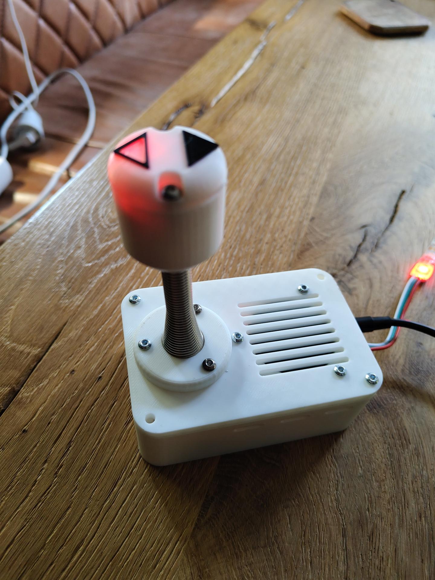
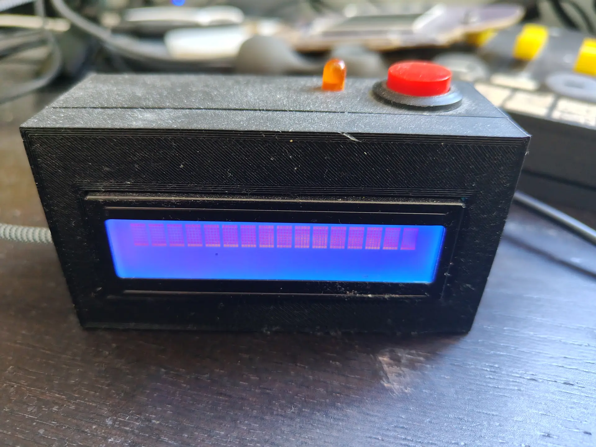
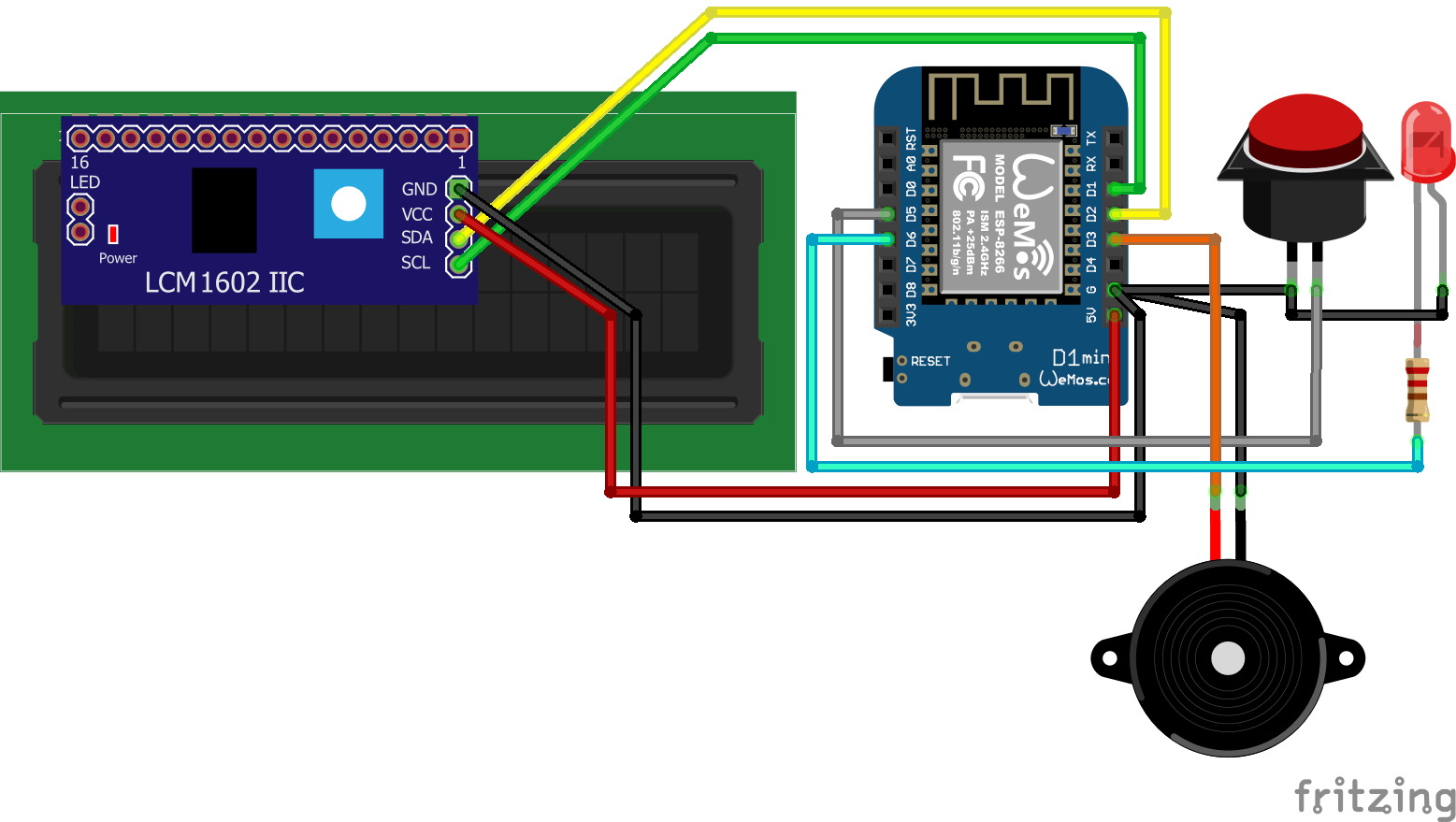
A while ago I made a little notify thingy using an LCD display, LED, button and a buzzer.
Some friends of mine made one also, and today I was talking to a new guy.
I could not find this project on my site .. again .. so I’ll post it now.
Some things it does right now
- Front door opens
- Door bell rings (because my lab is in the garden)
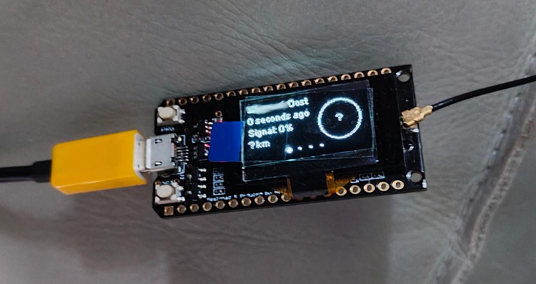
- Girlfriend is 10Km away, so let’s start cooking
- Garage door opens (friend of mine uses this to know when kids arrive)
- More .. because it’s very easy to customize in Home Assistant
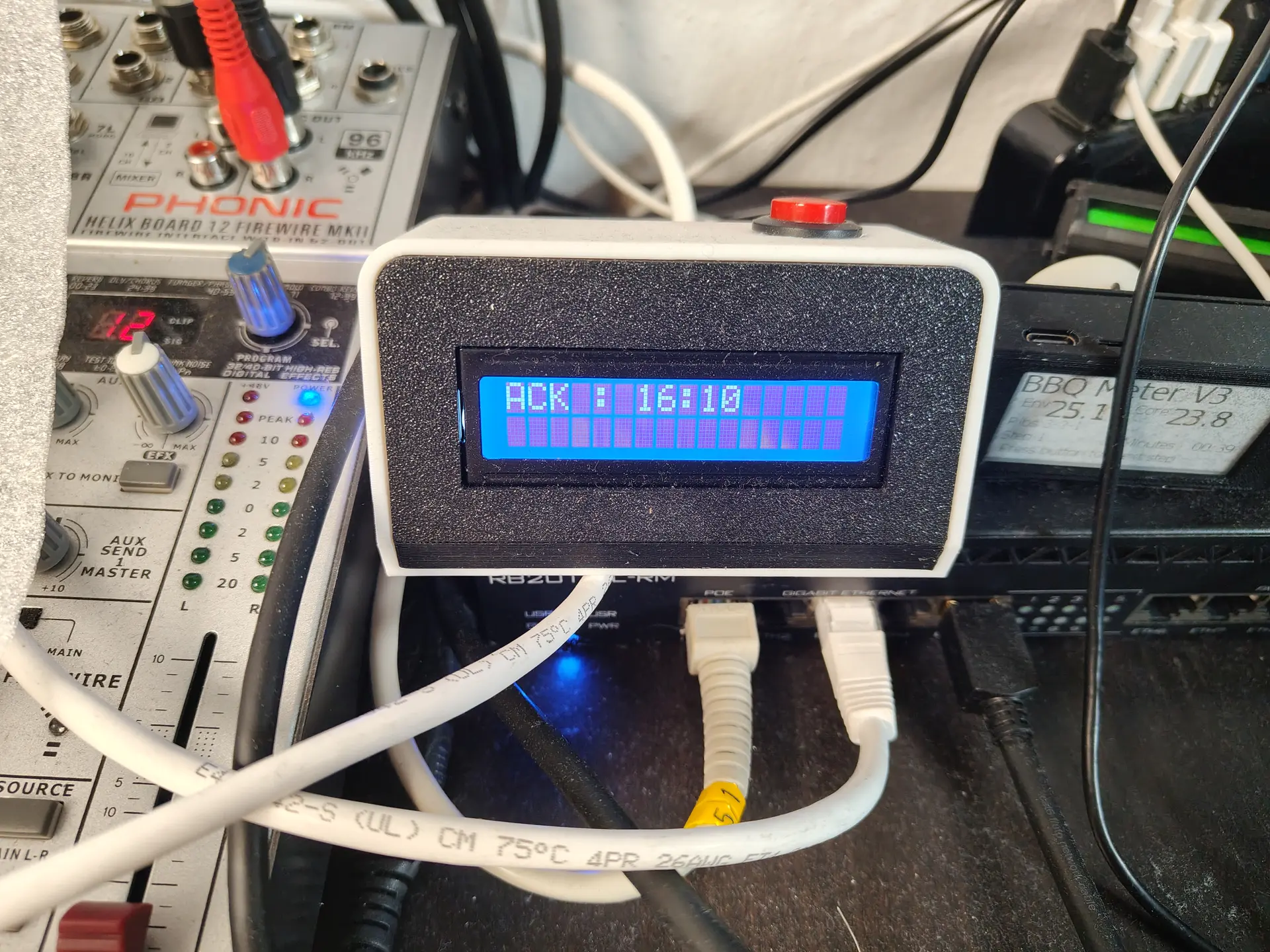
Doorbell pressed: Led starts blinking, backlight LCD enabled, text displayed on LCD, Buzzer sounds (or plays a RTTTL ringtone)
LCD backlight on and buzzer beep until acknowledge button pressed.
Heating for brewing: temperature on display, led on when temperature reached. Press acknowledge to start timer.
….. etc
CODE:
esphome:
  name: lcdalarm
  friendly_name: LCDAlarm
  on_boot:
    priority: -100.0
    then:
      - lambda: 'id(lcddisplay).no_backlight();'

esp8266:
  board: d1_mini

# Enable logging
logger:

# Enable Home Assistant API
api:
  encryption:
    key: "OOpDzMu0VvfWAnJXXXXXXXXXXXXXXXXXXXXXXXXKNDa74OJ1Cc="

ota:
   - platform: esphome
     password: "627992017XXXXXXXXXXXXXXX738c2a3"

wifi:
  ssid: !secret wifi_ssid
  password: !secret wifi_password

  # Enable fallback hotspot (captive portal) in case wifi connection fails
  ap:
    ssid: "Lcdalarm Fallback Hotspot"
    password: "z9dZXXXXXXXX7a"

captive_portal:
web_server:
  port: 80

i2c:
  sda: D2
  scl: D1
  scan: true
  frequency: 400kHz

light:
  - platform: binary
    name: "Status LED"
    output: light_output
    icon: "mdi:led-on"
    id: led


binary_sensor:
  - platform: gpio
    pin:
      inverted: true
      number: D5
      mode:
        input: true
        pullup: true
    name: "LCD Button"

text_sensor:
  # Create text input helper in homeassistant and enter id below
  - platform: homeassistant
    entity_id: input_text.lcd_display_text
    id: lcd_display_text

  - platform: wifi_info
    ip_address:
      id: ip_address
      name: IP address
    mac_address:
      id: mac_address
      name: Mac address
    ssid:
      id: connected_ssid
      name: Network SSID
    bssid:
      id: connected_
      name: Network Mac

sensor:
  - platform: wifi_signal
    id: wifisignal
    name: wifi-signal
    update_interval: 300s

globals:
  - id: backlight_on
    type: bool
    initial_value: 'false'
  - id: flash_beep_on
    type: bool
    initial_value: 'false'

switch:
  - platform: template
    name: "LCD Backlight"
    id: backlight
    restore_mode: RESTORE_DEFAULT_OFF
    turn_on_action:
      - globals.set:
          id: backlight_on
          value: 'true'
      - globals.set:
          id: flash_beep_on
          value: 'false'
      - lambda: |-
          id(lcddisplay).backlight();
      - delay: 5s
    turn_off_action:
      - globals.set:
          id: backlight_on
          value: 'false'
      - lambda: |-
            id(lcddisplay).no_backlight();
    lambda: |-
      return id(backlight_on);

  - platform: template
    name: "Flash and Beep"
    id: flash_beep
    restore_mode: RESTORE_DEFAULT_OFF
    turn_on_action:
      - globals.set:
          id: flash_beep_on
          value: 'true'
      - globals.set:
          id: backlight_on
          value: 'false'
      - lambda: |-
          id(lcddisplay).backlight();
      - lambda: |-
          id(buzzer).turn_on();
      - delay: 0.75s
      - lambda: |-
          id(lcddisplay).no_backlight();
      - lambda: |-
          id(buzzer).turn_off();
      - delay: 0.75s
      - lambda: |-
          id(lcddisplay).backlight();
      - lambda: |-
          id(buzzer).turn_on();
      - delay: 0.75s
      - lambda: |-
          id(lcddisplay).no_backlight();
      - lambda: |-
          id(buzzer).turn_off();
      - delay: 0.75s
      - lambda: |-
          id(lcddisplay).backlight();
      - lambda: |-
          id(buzzer).turn_on();
      - delay: 0.75s
      - lambda: |-
          id(lcddisplay).no_backlight();
      - lambda: |-
          id(buzzer).turn_off();
      - delay: 0.75s
      - lambda: |-
          id(lcddisplay).backlight();
    turn_off_action:
      - globals.set:
          id: flash_beep_on
          value: 'false'
      - lambda: |-
            id(lcddisplay).no_backlight();
      - lambda: |-
          id(buzzer).turn_off();
    lambda: |-
      return id(flash_beep_on);


  - platform: restart
    name: "Restart ESPhome"

output:
  - platform: gpio
    pin: D3
    id: buzzer
  - platform: gpio
    pin: D6
    id: light_output

display:
  - platform: lcd_pcf8574
    id: lcddisplay
    dimensions: 16x2
    address: 0x27
    lambda: |-
      if(id(wifisignal).has_state()) {
        if (id(lcd_display_text).state != "") {
          it.print(0, 0, id(lcd_display_text).state.c_str());
        }
      } else {
        it.print("    ESPhome        booting...   ");
      }
CODE: RTTTL (Use passive buzzer!!!!)
esphome:
  name: lablcd
  friendly_name: LabLCD

esp8266:
  board: d1_mini

# Enable logging
logger:

# Enable Home Assistant API
api:
  encryption:
    key: "ga17mNCtxdiXXXXXXXXXXXXXXXXXXXXX70a5W0VPZR51Q="
  actions:
    - action: rtttl_play
      variables:
        song_str: string
      then:
        - rtttl.play:
            rtttl: !lambda 'return song_str;'

ota:
  - platform: esphome
    password: "84013b9XXXXXXXXXXXXXXX5401039f7c"

wifi:
  ssid: !secret wifi_ssid
  password: !secret wifi_password

  # Enable fallback hotspot (captive portal) in case wifi connection fails
  ap:
    ssid: "Lablcd Fallback Hotspot"
    password: "nnzXXXXXXXXXXXXXXXXXXXCb"

rtttl:
  output: rtttl_out
  on_finished_playback:
    - logger.log: 'Song ended!'


captive_portal:

i2c:
  sda: D2
  scl: D1
  scan: true
  frequency: 400kHz

light:
  - platform: status_led
    name: "Status LED"
    icon: "mdi:led-on"
    pin:
      number: D5
      inverted: true

binary_sensor:
  - platform: gpio
    name: "Push Button"
    pin:
      number: D4
      inverted: true
      mode:
        input: true
        pullup: true
    on_press:
      - homeassistant.service:
          service: homeassistant.toggle
          data:
            entity_id: input_boolean.esphome_notification_lcdlab_push_button

text_sensor:
  # Create text input helper in homeassistant and enter id below
  - platform: homeassistant
    entity_id: input_text.esphome_notification_lcdlcd_display_text
    id: lcd_display_text

  - platform: wifi_info
    ip_address:
      id: ip_address
      name: IP address
    mac_address:
      id: mac_address
      name: Mac address
    ssid:
      id: connected_ssid
      name: Network SSID
    bssid:
      id: connected_
      name: Network Mac

sensor:
  - platform: wifi_signal
    id: wifisignal
    name: wifi-signal
    update_interval: 300s

globals:
  - id: backlight_on
    type: bool
    initial_value: 'false'
  - id: flash_beep_on
    type: bool
    initial_value: 'false'

switch:
  - platform: template
    name: "LCD Backlight Lab"
    id: backlight
    restore_mode: RESTORE_DEFAULT_OFF
    turn_on_action:
      - globals.set:
          id: backlight_on
          value: 'true'
      - globals.set:
          id: flash_beep_on
          value: 'false'
      - lambda: |-
          id(lcddisplay).backlight();
    turn_off_action:
      - globals.set:
          id: backlight_on
          value: 'false'
      - lambda: |-
            id(lcddisplay).no_backlight();
    lambda: |-
      return id(backlight_on);


  - platform: restart
    name: "Restart ESPhome"

output:
  - platform: esp8266_pwm
    pin: D8
    id: rtttl_out

display:
  - platform: lcd_pcf8574
    id: lcddisplay
    dimensions: 16x2
    address: 0x27
    lambda: |-
      if(id(wifisignal).has_state()) {
        if (id(lcd_display_text).state != "") {
          it.print(0, 0, id(lcd_display_text).state.c_str());
        }
      } else {
        it.print("    ESPhome        booting...   ");
      }