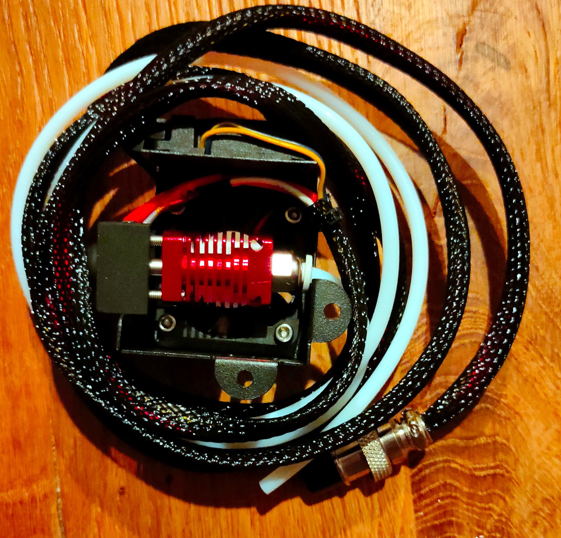
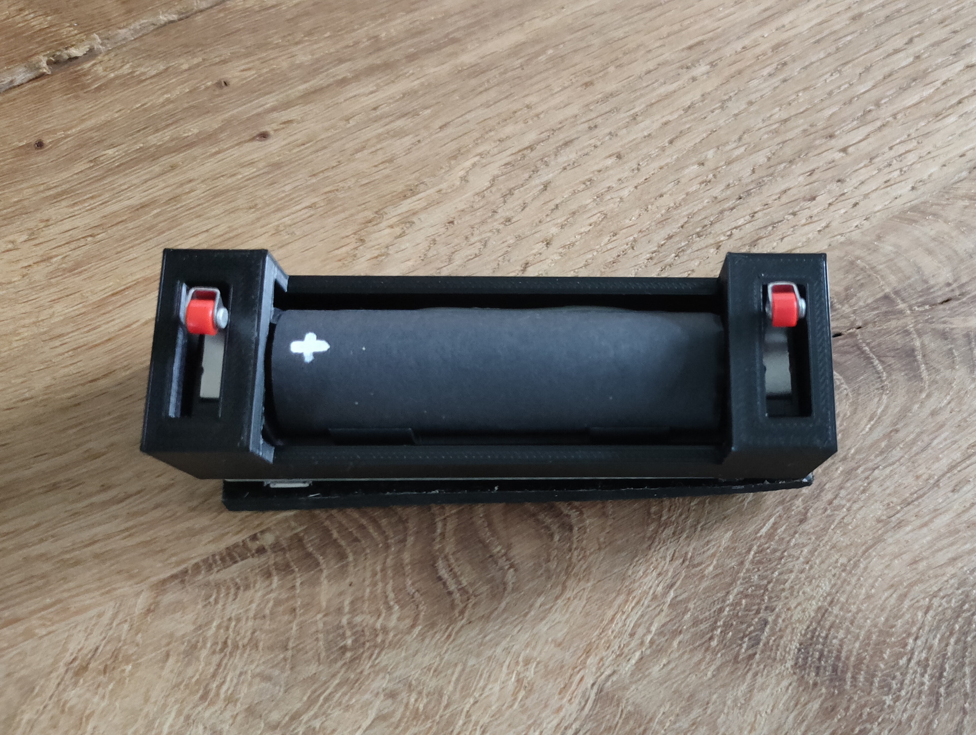
Back in 2019 I made a volume/mute button using an ATtiny85.
(Digispark/trinkey thingy)
Same device as my password paster
It’s USB connection is perfect for this password paste thingy, but not for a big button like this. (even with a ugly usb extending cable)
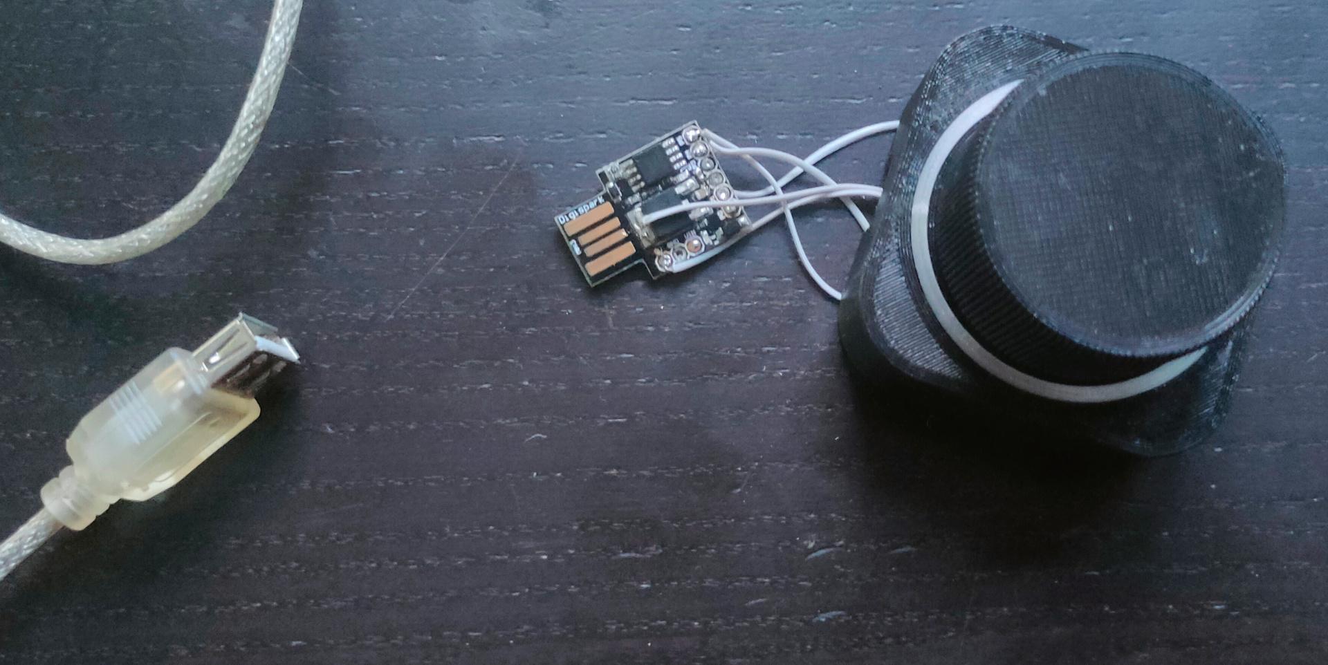
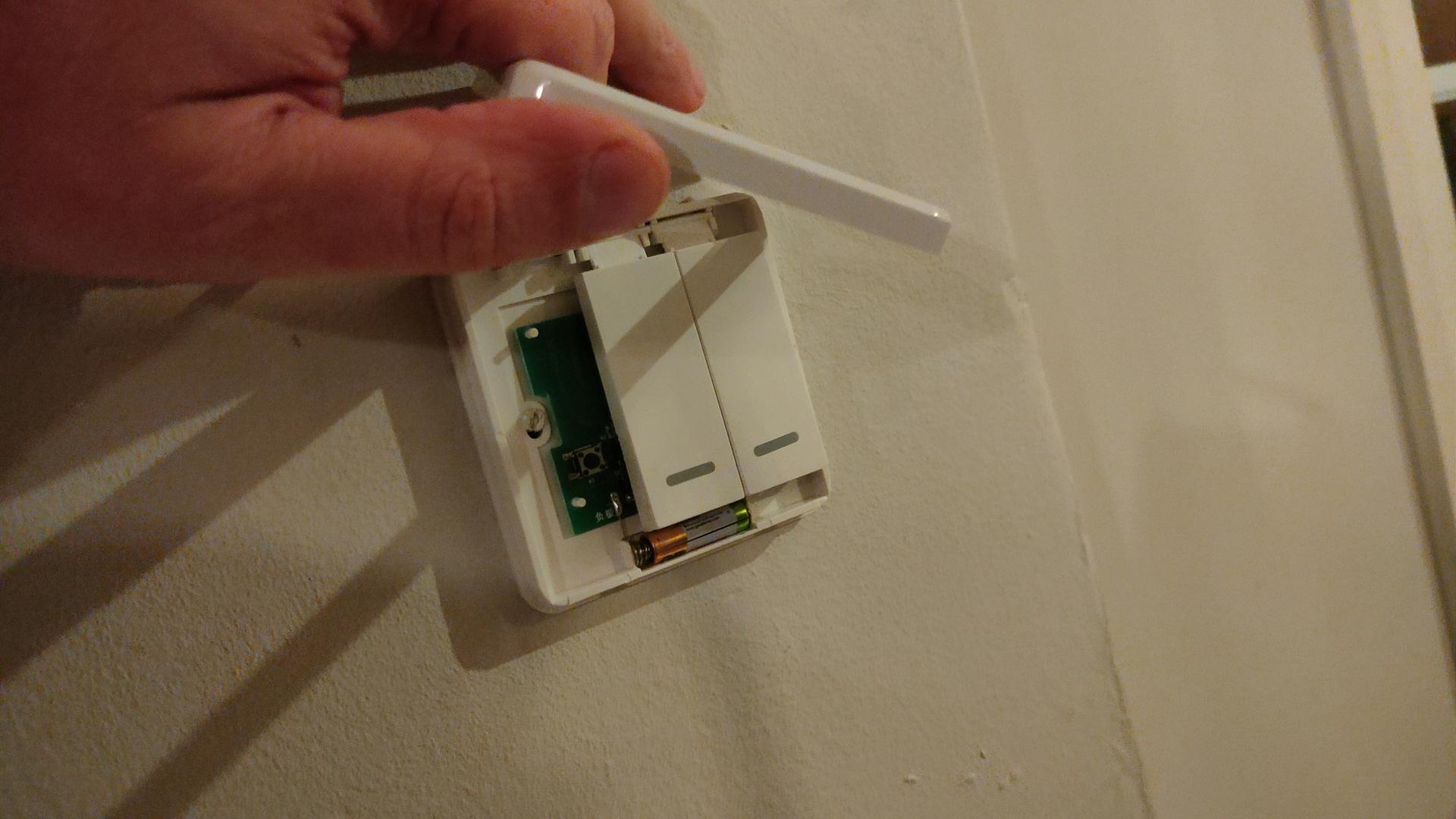
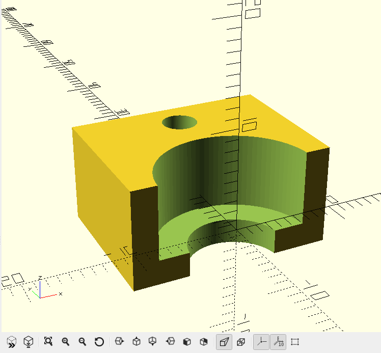
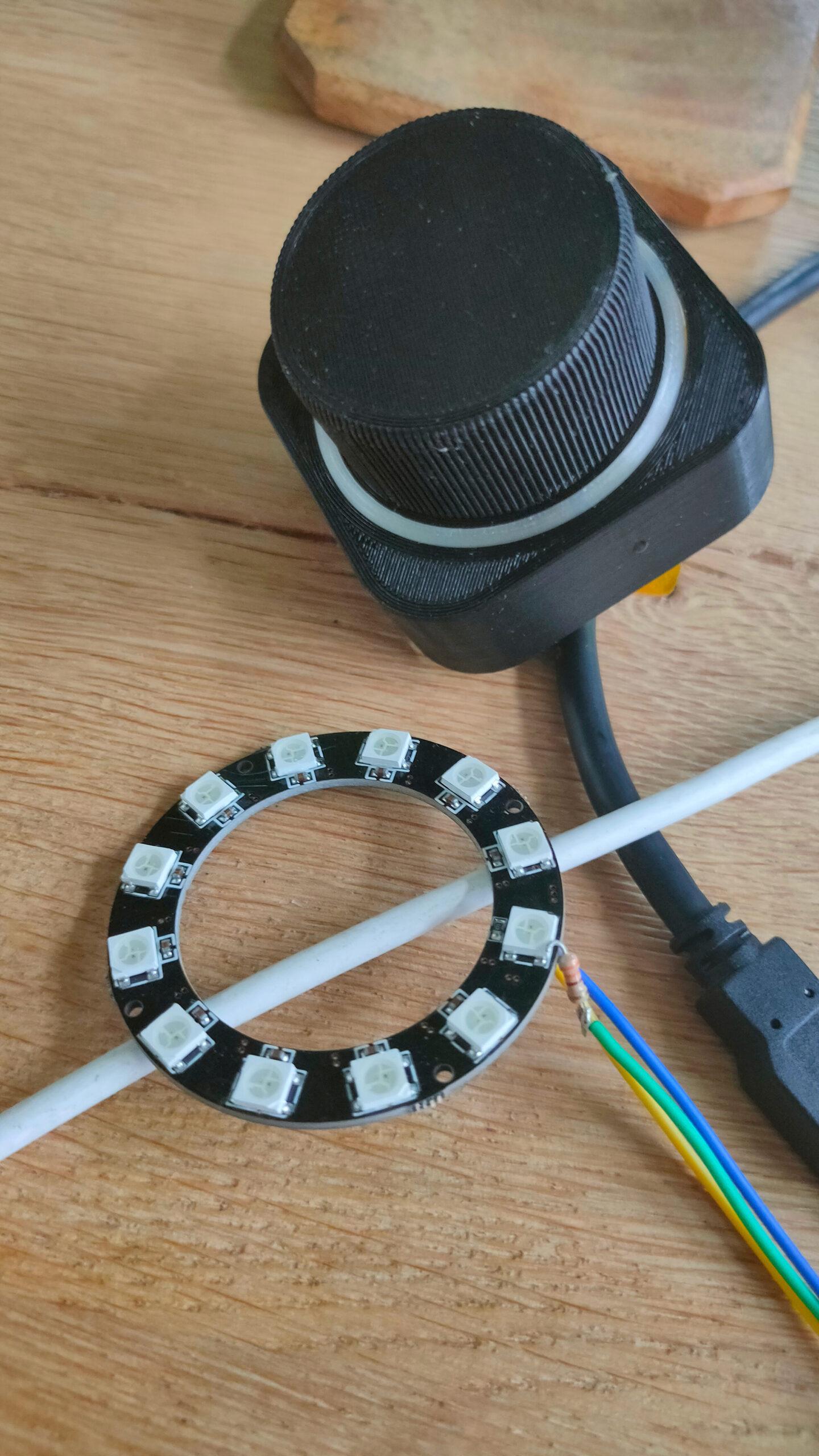
Button is 3D printed (found on yeggi)
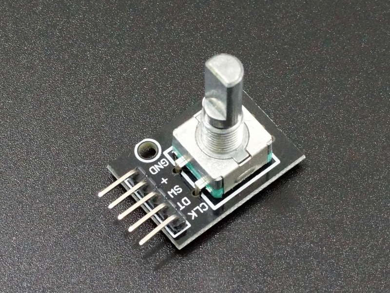
For my big battlestation i’m using:
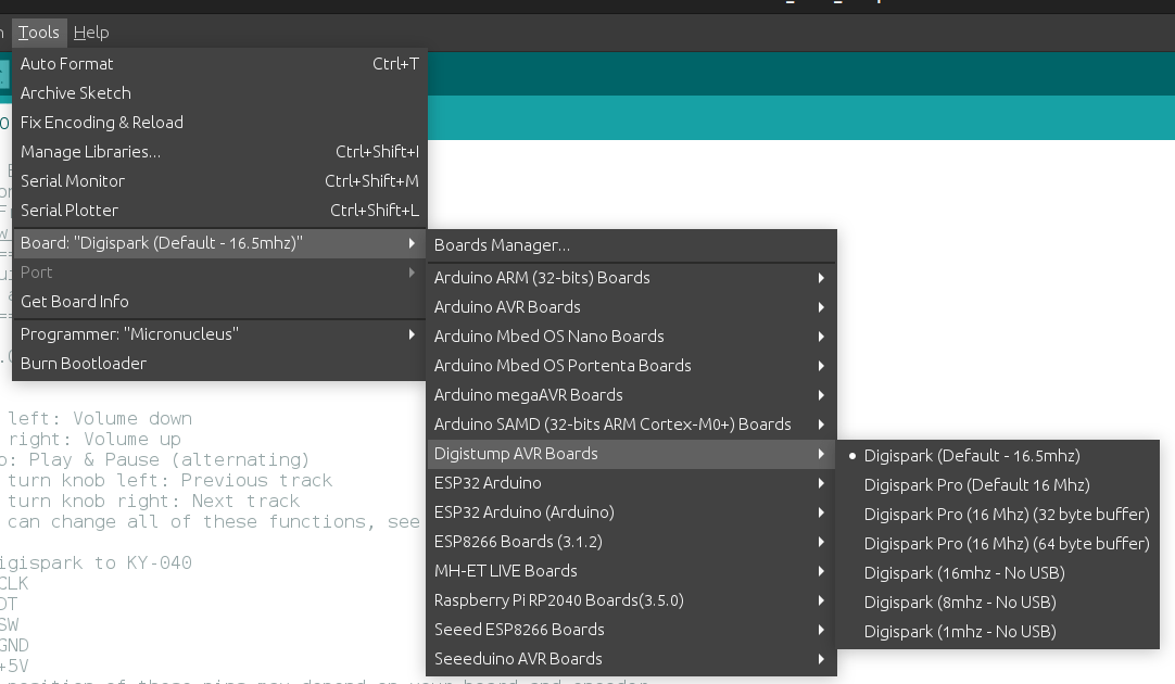
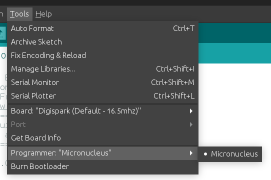
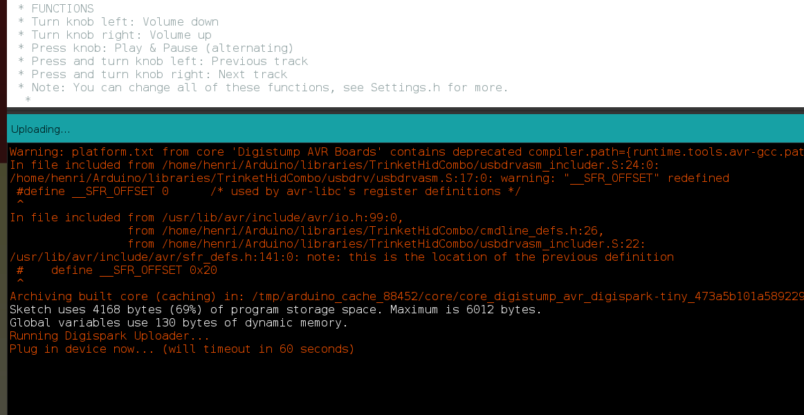
The old way of flashing using Arduino IDE (for digispark)
Install Boards using : preferences, add board URL
http://digistump.com/package_digistump_index.json
Note: There being no regular USB device, you need to add some udev rules.
cat /etc/udev/rules.d/digispark.rules
SUBSYSTEM==”usb”, ATTR{idVendor}==”16d0″, ATTR{idProduct}==”0753″, MODE=”0660″, GROUP=”dialout”
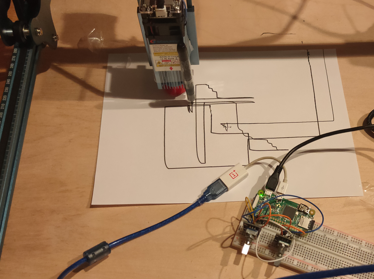
When compiling and uploading the program, you get a message to plug in the device. See below screenshot.
Now the 2024 change.
Reason to change:
- Want to have USB-C
- Python to get a more flexible setup
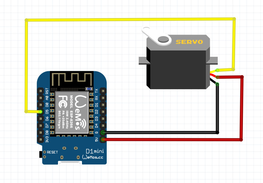
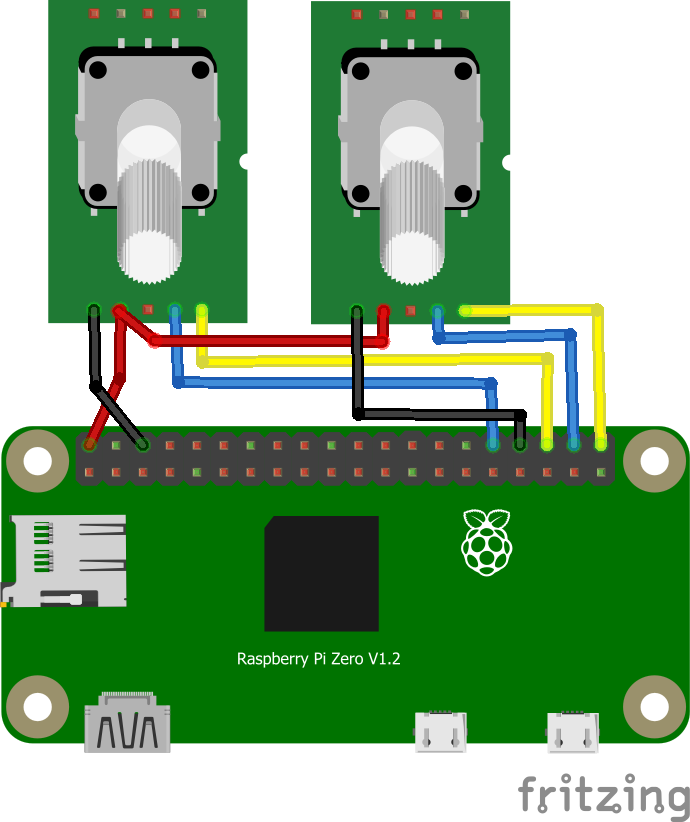
- I want to use more pins, so I can add LEDs and more buttons.
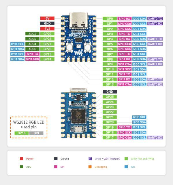
- I wanted to play with my Waveshare RP2040 Zero.
This is the first setup, with same functionality as before.
Now I can add more stuff!
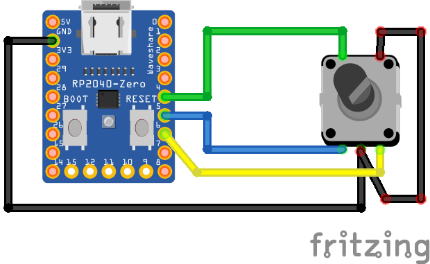
Putting the code on the RP2040-zero
Press boot button and insert into your pc.
Download uf2 file from here and save in RP2 drive.
https://circuitpython.org/board/waveshare_rp2040_zero/
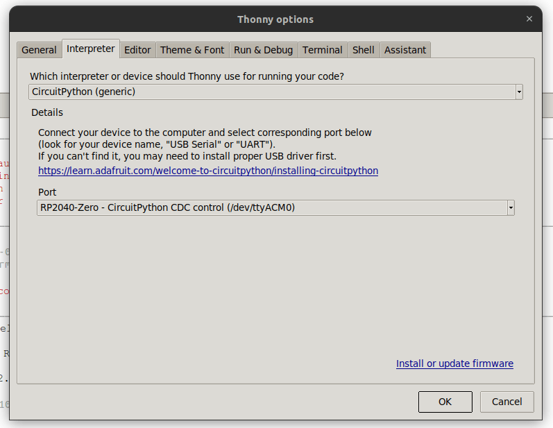
Open Thonny, and configure interpreter to:
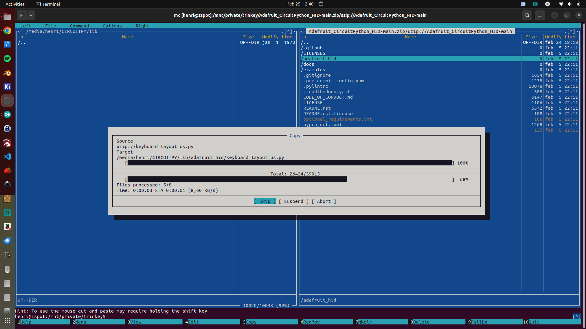
Download the zip file from https://github.com/adafruit/Adafruit_CircuitPython_HID
And copy only the subdirectory adafruit_hid to the drive in subdir lib
Open the file code.py from the device, and remove example hello world code.
Paste in the following code.
import rotaryio
import board
import time

import board
import digitalio
import usb_hid
from adafruit_hid.keyboard import Keyboard
from adafruit_hid.keyboard_layout_us import KeyboardLayoutUS
from adafruit_hid.keycode import Keycode
from adafruit_hid.consumer_control import ConsumerControl
from adafruit_hid.consumer_control_code import ConsumerControlCode

but = digitalio.DigitalInOut(board.GP4)
but.direction = digitalio.Direction.INPUT
but.pull = digitalio.Pull.UP

cc = ConsumerControl( usb_hid.devices )

encoder = rotaryio.IncrementalEncoder(board.GP5, board.GP6)
last_position = 0
while True:
    position = encoder.position
    if int(last_position) < int(position):
        #print(position)
        command = ConsumerControlCode.VOLUME_DECREMENT
        cc.send(command)
    #last_position = position
    if int(last_position) > int(position):
        #print(position)
        command = ConsumerControlCode.VOLUME_INCREMENT
        cc.send(command)
    last_position = position
    if not but.value:
        command = ConsumerControlCode.MUTE
        cc.send(command)
        time.sleep(0.5)
Above code is the bare minimum, I’ll add more functionality soon.
(LEDs and more buttons)
Next and Previous Track and mode change.
From Audio to Navigation for example.