I always wanted to have everything on my fileserver. But indexing or searching for the right document is a pain in the *ss.
I wrote several tools for this but wanted to try something new.
Maybe its a perfect solution for all my datasheets I use in my electronics as well.
So I installed Paperless-ngx using docker.
Paperless-ngx is a community-supported open-source document management system that transforms your physical documents into a searchable online archive so you can keep, well, less paper.
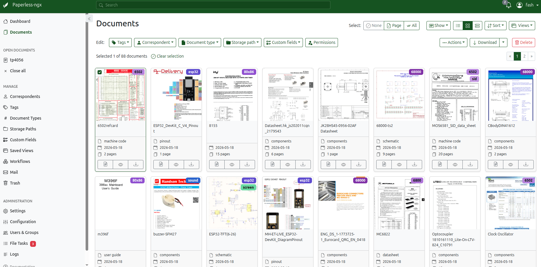
Features
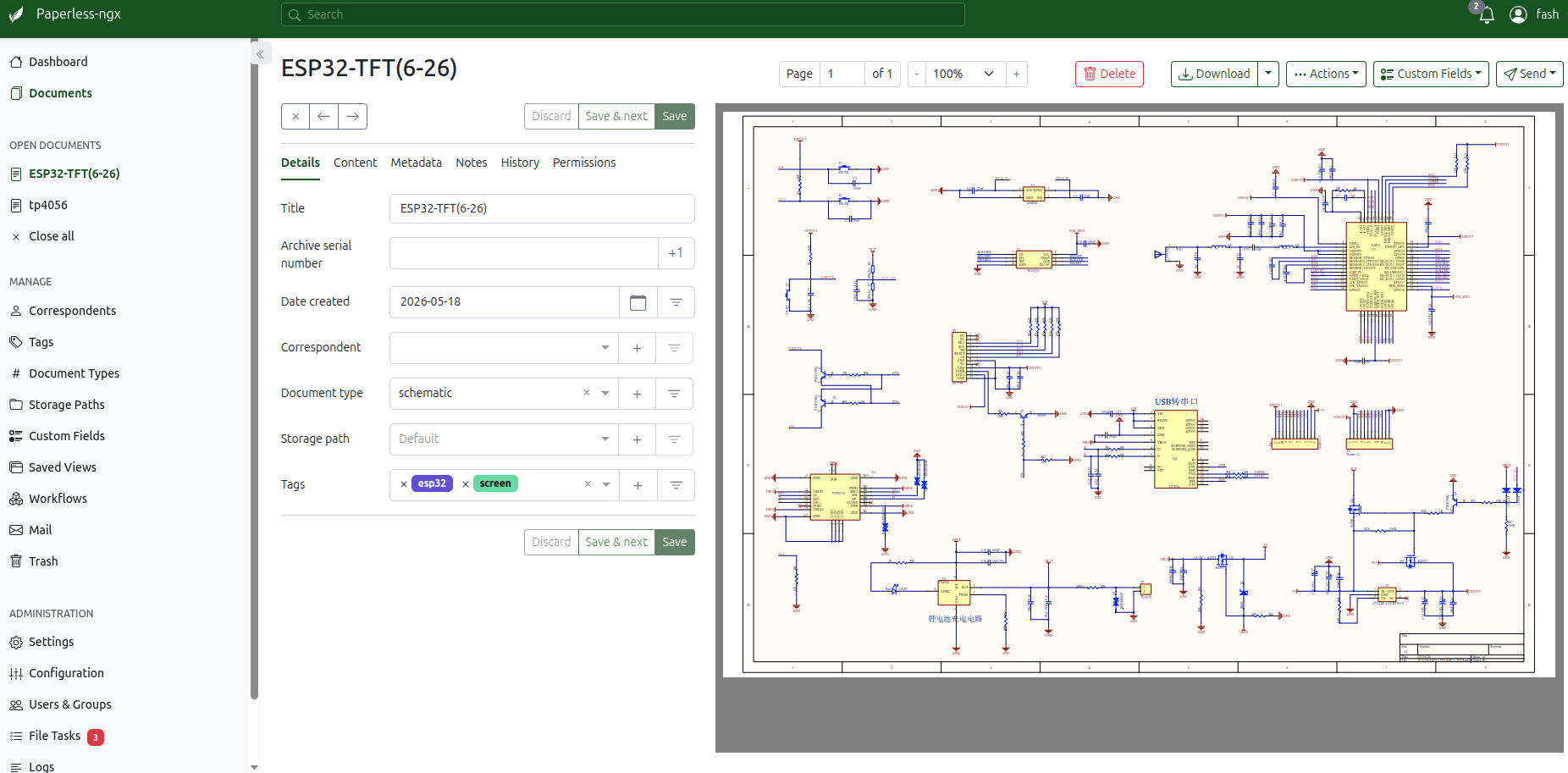
- Organize and index your scanned documents with tags, correspondents, types, and more.
- Your data is stored locally on your server and is never transmitted or shared in any way.
- Performs OCR on your documents, adding searchable and selectable text, even to documents scanned with only images.
- Utilizes the open-source Tesseract engine to recognize more than 100 languages.
- Documents are saved as PDF/A format which is designed for long term storage, alongside the unaltered originals.
- Uses machine-learning to automatically add tags, correspondents and document types to your documents.
- Supports PDF documents, images, plain text files, Office documents (Word, Excel, PowerPoint, and LibreOffice equivalents) and more.
- Paperless stores your documents plain on disk. Filenames and folders are managed by paperless and their format can be configured freely with different configurations assigned to different documents.
- Beautiful, modern web application that features:
- Customizable dashboard with statistics.
- Filtering by tags, correspondents, types, and more.
- Bulk editing of tags, correspondents, types and more.
- Drag-and-drop uploading of documents throughout the app.
- Customizable views can be saved and displayed on the dashboard and / or sidebar.
- Support for custom fields of various data types.
- Shareable public links with optional expiration.
- Full text search helps you find what you need:
- Auto completion suggests relevant words from your documents.
- Results are sorted by relevance to your search query.
- Highlighting shows you which parts of the document matched the query.
- Searching for similar documents (“More like this”)
- Email processing: import documents from your email accounts:
- Configure multiple accounts and rules for each account.
- After processing, paperless can perform actions on the messages such as marking as read, deleting and more.
- A built-in robust multi-user permissions system that supports ‘global’ permissions as well as per document or object.
- A powerful workflow system that gives you even more control.
- Optimized for multi core systems: Paperless-ngx consumes multiple documents in parallel.
- The integrated sanity checker makes sure that your document archive is in good health.
I’ll keep adding to this page at a later time