Info:
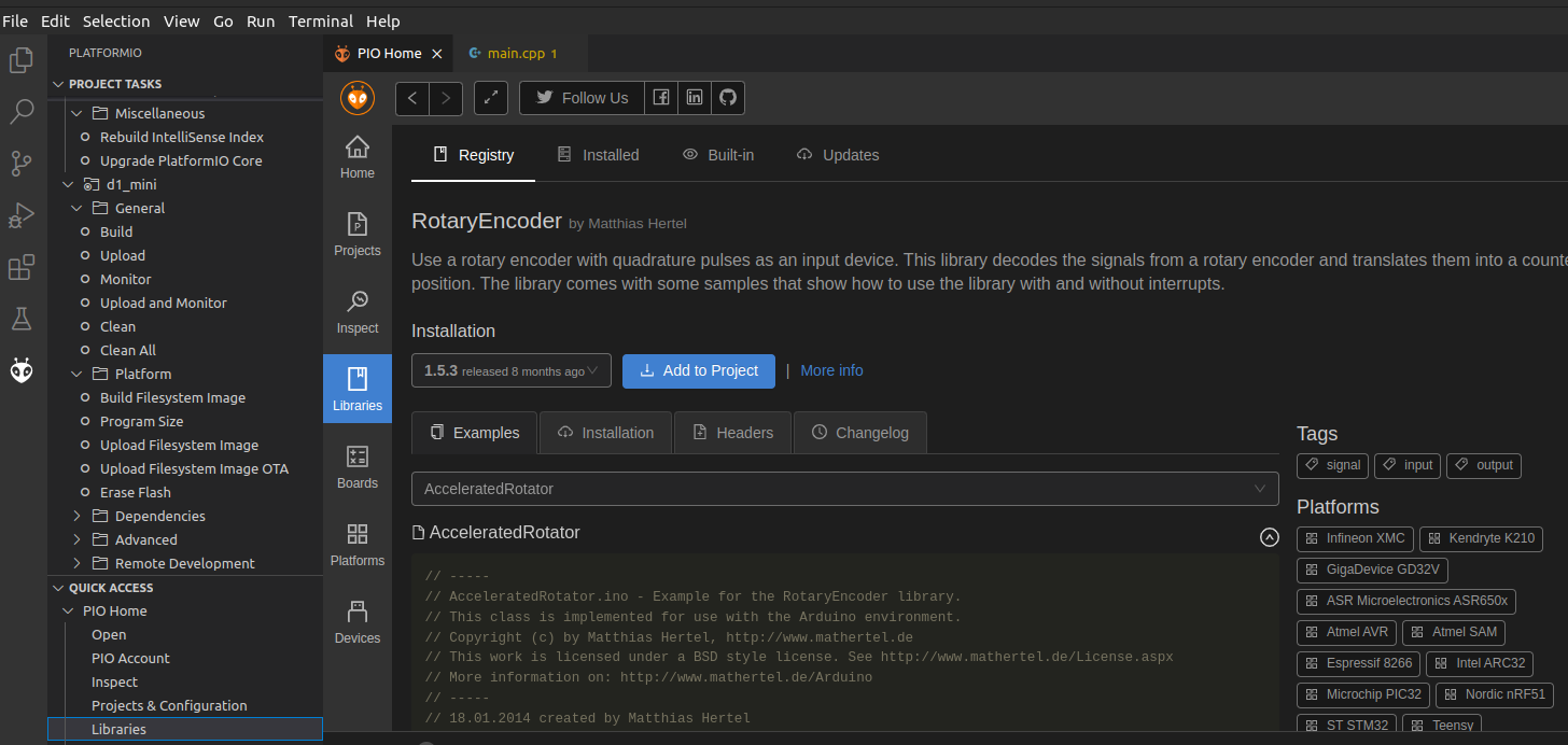
- PlatformIO tested ( install StackArray.h in lib/StackArray/StackArray.h )
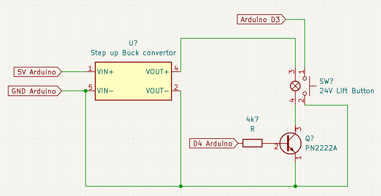
- Reset button and dipswitches for below options
- Visited pathmode ( dip switch 1)
- Preview maze generation ( dip switch 3)
- Hard mode – starts at first position when hitting a wall ( dip 2 )
- Longest path mode (longest stackarray before stack.pop (dip 4 )
- Prints serial info, like a drawn maze
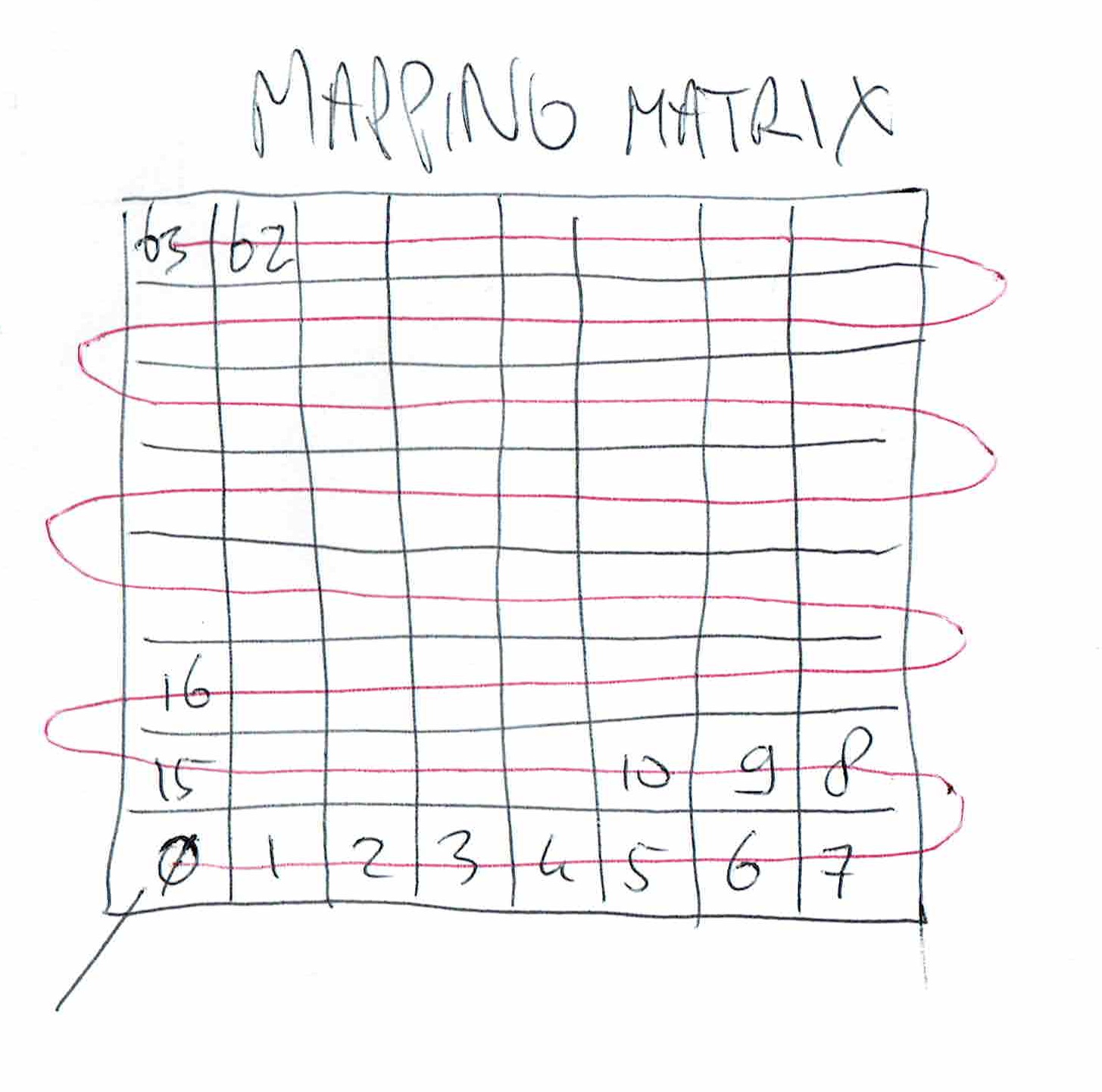
- Pixel remapping for other displays ( Below mapping i had to use, see source sketch )
- Visited pathmode ( dip switch 1)
- Reset button and dipswitches for below options
How is the maze generated?
It is generated using recursive backtracking:
Start at 0,0 mark visited, select a random direction from unvisited neighbours, push current on the stack, goto new location, and mark this visited.
Repeat until no possible directions.
pop from the stack a previous location, another direction possible? Take that path and repeat.
Repeat popping from stack, until stack empty .. now all cells are visited
longest pop : 41
maze
------------------------
|    ||    ||       || |
---            ---
| ||    ||    ||    || |
   ------------   ---
|       || ||    ||    |
   ---         ---   ---
|    ||    || ||       |
      ---         ---
| || || || || || ||    |

| || || || || || || || |
---
|    ||    || || || || |
   ---------   ---
|                   || |
------------------------
x y : 00
maze 4
|4|3|6|3|6|5|3|2|
|2|12|9|12|9|6|9|10|
|14|5|3|2|6|9|6|9|
|14|3|12|11|10|6|13|3|
|10|10|2|10|10|10|6|11|
|8|10|10|10|10|10|10|10|
|6|9|12|9|10|8|10|10|
|12|5|5|5|13|5|9|8|
Easiest play mode: Preview Maze, Show visited path, NO reset to square 0,0 and NOT the longest path so :
| Show visited DIP1 | Reset to 0,0 DIP2 | Preview DIP3 | Longest path DIP4 |
| 1 | 0 | 1 | 0 |
Hard mode:
| Show visited DIP1 | Reset to 0,0 DIP2 | Preview DIP3 | Longest path DIP4 |
| 0 | 1 | 0 | 1 |
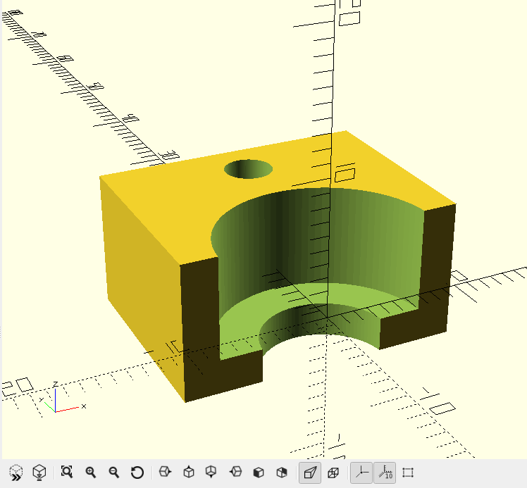
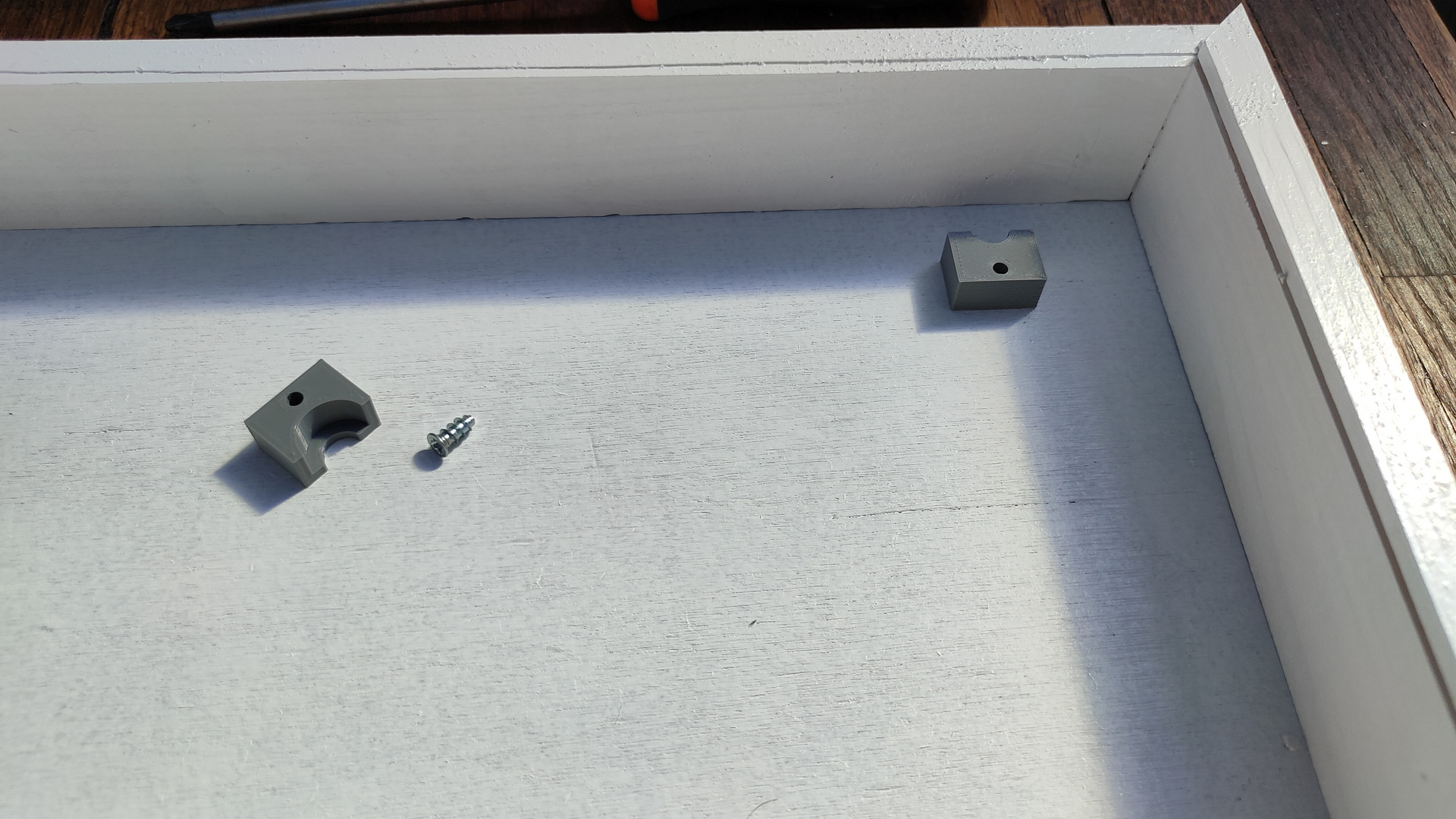
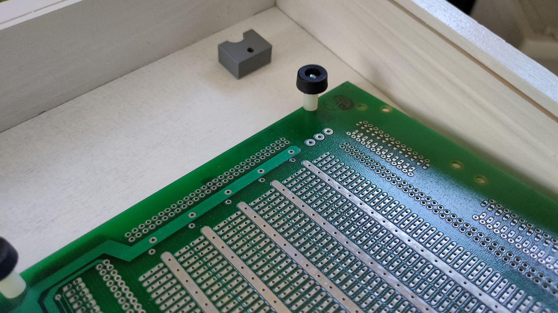
Todo: Battery / batterymanager / 3D case / better buttons
Some video shorts put together to show modes
CODE
#include <Arduino.h>
#include <Adafruit_NeoPixel.h>
#include "StackArray.h"
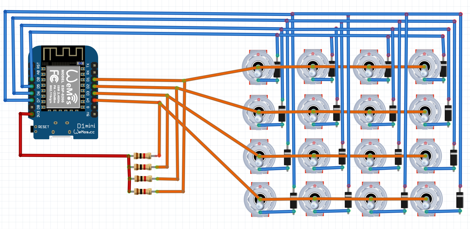
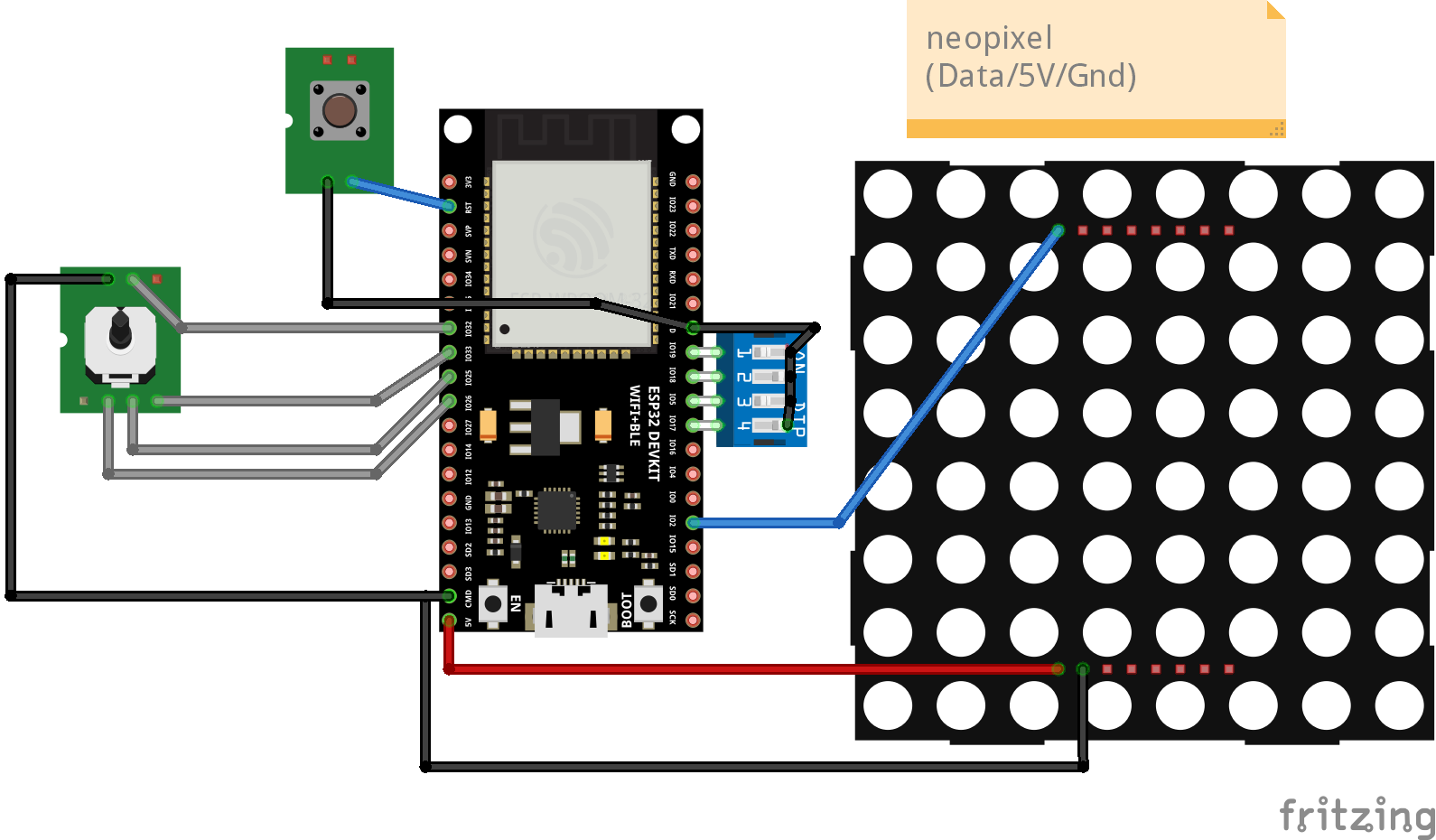
// Pin Assign
int up=25;
int down=33;
int left=32;
int right=26;
int trailsw=17;
int restartsw=5;
int showmazesw=18;
int popendsw=19;
int xend=7;
int yend=7;
int countpop=0;
int currentpop=0;
int directions[4]{};
int notalldone = 1;
int tmpx=0;
int tmpy=0;
int xgen = 1;
int ygen = 1;
int x = 0;
int y = 0;
int showmaze = 0;
// 0 easy = trail // 1 only red walls // 2 = reset to 0.0
int mode=0;
//int trail=32;
int trail=32;
// Which pin on the Arduino is connected to the NeoPixels?
#define LED_PIN 2
// How many NeoPixels are attached to the Arduino?
#define LED_COUNT 64
// Declare our NeoPixel strip object:
Adafruit_NeoPixel strip(LED_COUNT, LED_PIN, NEO_GRB + NEO_KHZ800);
int maze[8][8] = {
};
int displaymatrix[8][8] = {
{ 0,1,2,3,4,5,6,7 },
{ 15,14,13,12,11,10,9,8 },
{16,17,18,19,20,21,22,23},
{31,30,29,28,27,26,25,24},
{32,33,34,35,36,37,38,39},
{47,46,45,44,43,42,41,40},
{48,49,50,51,52,53,54,55},
{63,62,61,60,59,58,57,56}
};
int visitmatrix[10][10] = {
1,1,1,1,1,1,1,1,1,1,
1,0,0,0,0,0,0,0,0,1,
1,0,0,0,0,0,0,0,0,1,
1,0,0,0,0,0,0,0,0,1,
1,0,0,0,0,0,0,0,0,1,
1,0,0,0,0,0,0,0,0,1,
1,0,0,0,0,0,0,0,0,1,
1,0,0,0,0,0,0,0,0,1,
1,0,0,0,0,0,0,0,0,1,
1,1,1,1,1,1,1,1,1,1
};
void(* resetFunc) (void) = 0;
void drawmaze2(){
Serial.print("x y : ");
Serial.print(x);
Serial.println(y);
Serial.print("maze ");
Serial.println(maze[x][y]);
for(int ledy=0;ledy<8;ledy++)
{ Serial.print("|");
for(int ledx=0;ledx<8;ledx++){
Serial.print(maze[ledx][ledy]);
Serial.print("|");
if ( maze[ledx][ledy] != 0 ) {
// mled.dot(ledx,ledy); // draw dot
// mled.display();
// delay(50);
}
}
Serial.println("");
}
Serial.println("");
delay(100);
}
void drawmaze(){
Serial.println("maze ");
for(int ledy=0;ledy<8;ledy++)
{
// 1st line
for(int ledx=0;ledx<8;ledx++){
if(bitRead(maze[ledx][ledy], 3) == 0){ Serial.print("---"); } else { Serial.print(" "); }
}
Serial.println("");
// 2nd line
for(int ledx=0;ledx<8;ledx++){
if(bitRead(maze[ledx][ledy], 0) == 1){
if(bitRead(maze[ledx][ledy], 2) == 1){
Serial.print(" "); }
else
{ Serial.print(" |"); }
}
if(bitRead(maze[ledx][ledy], 0) == 0){
if(bitRead(maze[ledx][ledy], 2) == 1){
Serial.print("| "); }
else
{ Serial.print("| |"); }
}
}
Serial.println("");
}
// last line
int ledy=7;
for(int ledx=0;ledx<8;ledx++){
if(bitRead(maze[ledx][ledy], 1) == 0){ Serial.print("---"); } else { Serial.print(" "); }
}
Serial.println("");
//Serial.println("");
delay(100);
}
void mazegen(){
visitmatrix[xgen][ygen]=1;
StackArray <int> rowStack;
StackArray <int> colStack;
rowStack.push(xgen);
colStack.push(ygen);
while(notalldone == 1){
visitmatrix[xgen][ygen]=1;
while(!rowStack.isEmpty()) {
int count=0;
//up
if ( visitmatrix[xgen-1][ygen] == 0 ){
directions[count]=1;
count++;
}
//right
if ( visitmatrix[xgen][ygen+1] == 0 ){
directions[count]=2;
count++;
}
//down
if ( visitmatrix[xgen+1][ygen] == 0 ){
directions[count]=4;
count++;
}
//left
if ( visitmatrix[xgen][ygen-1] == 0 ){
directions[count]=8;
count++;
}
if (showmaze == 1 ){
strip.setPixelColor(displaymatrix[xgen-1][ygen-1], 32, 32, 32);
strip.show();
delay(50);
}
// no dir found
if (count == 0 ) {
if (digitalRead(popendsw) == 0 ){
currentpop = rowStack.count();
if (currentpop > countpop ) {
countpop = currentpop;
xend = xgen-1;
yend = ygen-1;
Serial.print("longest pop : ");
Serial.println(currentpop);
}
}
// mled.dot(x-1,y-1);
// mled.display();
xgen = rowStack.pop();
ygen = colStack.pop();
// Serial.println("popping ");
} else {
// count random direction
int dir = directions[random(count)];
//Serial.println("push ");
rowStack.push(xgen);
colStack.push(ygen);
// Serial.print("nr dir : ");
// Serial.println(count);
//delay(100);
// Serial.println(dir);
// move 1,1 to 0,0
//mled.dot(x-1,y-1);
//mled.display();
// set direction in maze, dit moet bit set worden
int mybits = maze[xgen-1][ygen-1];
int storedir = mybits | dir;
maze[xgen-1][ygen-1] = storedir;
if ( dir == 1){
int getup = maze[xgen-2][ygen-1];
int storedir = getup | 4;
maze[xgen-2][ygen-1] = storedir;
}
if ( dir == 2){
int getup = maze[xgen-1][ygen];
int storedir = getup | 8;
maze[xgen-1][ygen] = storedir;
}
if ( dir == 4){
int getup = maze[xgen][ygen-1];
int storedir = getup | 1;
maze[xgen][ygen-1] = storedir;
}
if ( dir == 8){
int getup = maze[xgen-1][ygen-2];
int storedir = getup | 2;
maze[xgen-1][ygen-2] = storedir;
}
// maze[x-1][y-1] = dir;
//set new square
if (dir == 1){ xgen--; }
if (dir == 2){ ygen++; }
if (dir == 4){ xgen++; }
if (dir == 8){ ygen--; }
visitmatrix[xgen][ygen]=1;
//drawmaze();
}
}
notalldone = 0; //#2
// if found 0 in 10x10 matrix visited, do
for(int checkx=0;checkx<10;checkx++){
for(int checky=0;checky<10;checky++){
if ( visitmatrix[checkx][checky] == 0 ){
tmpx=xgen;
tmpy=ygen;
notalldone = 1;
}
}
}
}
rowStack.push(tmpx);
colStack.push(tmpy);
}
void setup() {
pinMode(32, INPUT_PULLUP);
pinMode(33, INPUT_PULLUP);
pinMode(25, INPUT_PULLUP);
pinMode(26, INPUT_PULLUP);
pinMode(popendsw, INPUT_PULLUP);
pinMode(trailsw, INPUT_PULLUP);
pinMode(restartsw, INPUT_PULLUP);
pinMode(showmazesw, INPUT_PULLUP);
Serial.begin(115200);
strip.begin();
strip.show(); // Initialize all pixels to 'off'
strip.setBrightness(10);
unsigned long seed = 0;
for (int i=0; i<32; i++)
{
seed = seed | ((analogRead(A0) & 0x01) << i);
}
randomSeed(seed);
if (digitalRead(showmazesw) == 0){
showmaze = 1;
}
mazegen();
drawmaze();
drawmaze2();
strip.fill(0, 0, 64);
strip.show(); // Initialize all pixels to 'off'
strip.setPixelColor(displaymatrix[x][y], 0, 0, 255);
strip.setPixelColor(displaymatrix[xend][yend], 0, 255, 0);
strip.show();
x=0;
y=0;
}
uint32_t Wheel(byte WheelPos) {
WheelPos = 255 - WheelPos;
if(WheelPos < 85) {
return strip.Color(255 - WheelPos * 3, 0, WheelPos * 3);
}
if(WheelPos < 170) {
WheelPos -= 85;
return strip.Color(0, WheelPos * 3, 255 - WheelPos * 3);
}
WheelPos -= 170;
return strip.Color(WheelPos * 3, 255 - WheelPos * 3, 0);
}
void reset2start() {
strip.setPixelColor(displaymatrix[x][y], 0, 0, 0);
strip.show();
x = 0;
y = 0;
strip.begin();
strip.show(); // Initialize all pixels to 'off'
strip.setBrightness(10);
strip.setPixelColor(displaymatrix[x][y], 0, 0, 255);
strip.setPixelColor(displaymatrix[xend][yend], 0, 255, 0);
strip.show();
}
void rainbow(uint8_t wait) {
uint16_t i, j;
for(j=0; j<256; j++) {
for(i=0; i<strip.numPixels(); i++) {
strip.setPixelColor(i, Wheel((i+j) & 255));
}
strip.show();
delay(wait);
}
}
void loop() {
if (digitalRead(trailsw) == 0 ){
trail = 32;
} else { trail = 0; }
if (digitalRead(restartsw) == 0 ){
mode = 2;
} else {
mode = 0;
}
int isUp = (bitRead(maze[x][y], 1));
int isRight = (bitRead(maze[x][y], 2));
int isDown = (bitRead(maze[x][y], 3));
int isLeft = (bitRead(maze[x][y], 0));
//isUp = 1;
//isDown = 1;
//isLeft = 1;
//isRight = 1;
if (digitalRead(up) == 0) {
if (isUp == 1){
strip.setPixelColor(displaymatrix[x][y], 0, 0, trail);
y++;
drawmaze();
if ( y > 7) { y=7;}
strip.setPixelColor(displaymatrix[x][y], 0, 0, 255);
strip.show();
} else {
strip.setPixelColor(displaymatrix[x][y], 255, 0, 0);
strip.show();
delay(100);
strip.setPixelColor(displaymatrix[x][y], 0, 0, 255);
strip.show();
if (mode == 2){
delay(1000);
reset2start();
}
}
}
if (digitalRead(down) == 0) {
if (isDown == 1){
strip.setPixelColor(displaymatrix[x][y], 0, 0, trail);
y--;
drawmaze();
if ( y < 0) { y=0;}
strip.setPixelColor(displaymatrix[x][y], 0, 0, 255);
strip.show();
} else {
strip.setPixelColor(displaymatrix[x][y], 255, 0, 0);
strip.show();
delay(100);
strip.setPixelColor(displaymatrix[x][y], 0, 0, 255);
strip.show();
if (mode == 2){
delay(1000);
reset2start();
}
}
}
if (digitalRead(left) == 0) {
drawmaze();
if (isLeft == 1){
strip.setPixelColor(displaymatrix[x][y], 0, 0, trail);
x--;
drawmaze();
if ( x < 0) { x=0;}
strip.setPixelColor(displaymatrix[x][y], 0, 0, 255);
strip.show();
} else {
strip.setPixelColor(displaymatrix[x][y], 255, 0, 0);
strip.show();
delay(100);
strip.setPixelColor(displaymatrix[x][y], 0, 0, 255);
strip.show();
if (mode == 2){
delay(1000);
reset2start();
}
}
}
if (digitalRead(right) == 0) {
drawmaze();
if (isRight == 1){
strip.setPixelColor(displaymatrix[x][y], 0, 0, trail);
x++;
drawmaze();
if ( x > 7) { x=7;}
strip.setPixelColor(displaymatrix[x][y], 0, 0, 255);
strip.show();
} else {
strip.setPixelColor(displaymatrix[x][y], 255, 0, 0);
strip.show();
delay(100);
strip.setPixelColor(displaymatrix[x][y], 0, 0, 255);
strip.show();
if (mode == 2){
delay(1000);
reset2start();
}
}
}
if (x ==xend && y == yend){
strip.begin();
strip.show(); // Initialize all pixels to 'off'
rainbow(20);
}
delay(200);
}