I never look in the mirror, so why do i need one? The mirror foil was already ugly in the corners. There were bumps. Never finished a proper interface
This one was made using a touch screen, so there are always fingerprints you could see
I’m going to use the display for an in-house small Escape Room idea i have.
Only the time part still worked, but i could not find the right cables for the touch part. The buttons displayed are meaningless anyway 🙂 Just a mockup
Mirror part was done using a Safety/One way mirror foil. Cut a part as large as you screen, spray a little water and stick it on.
At some point i displayed Dashticz on there. Apparently i started playing with a magic mirror setup in 2015, according some timestamps of code on my fileserver.
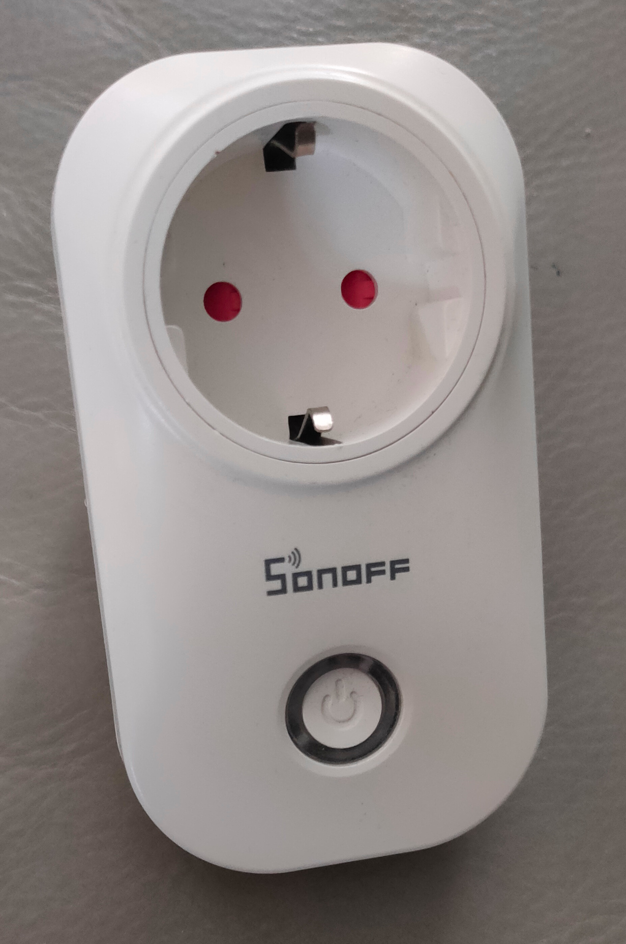
I previously had these smartplugs flashed with EspEasy (I hate cloud enabled devices) I will post something about flashing these and others. Maybe … because you can find a lot of information on the internet. But i’ve used several tools, and made tools for this process. ( Raspberry Zero mobile tool and 3D printed PCB holder for example)
Well ..
I was using these devices in our previous home using curl commands and on a main wifi network. So i have to change the SSID and migrate from Espeasy to ESPhome so i can use these devices with Home Assistant.
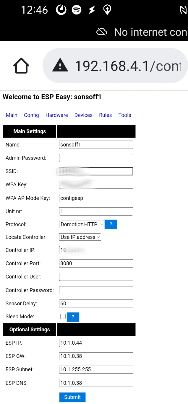
Step 1 : Start in Access Point mode and migrate to my current Wifi Iot network.
Using my phone i made the necessary changes.
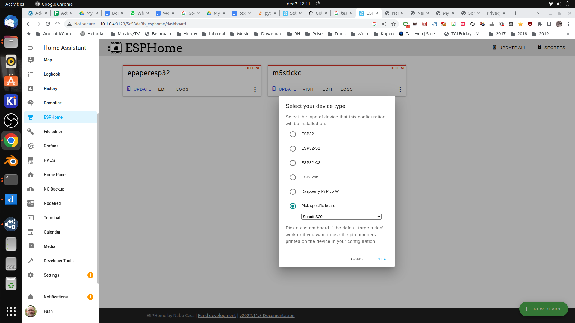
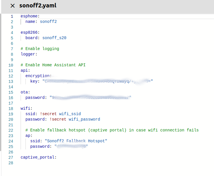
Goto HomeAssistant and ESPhome (you need to install this first via HACS) Press the green + Add device and give it a name
Next select the device type (Sonoff S20 in this case)
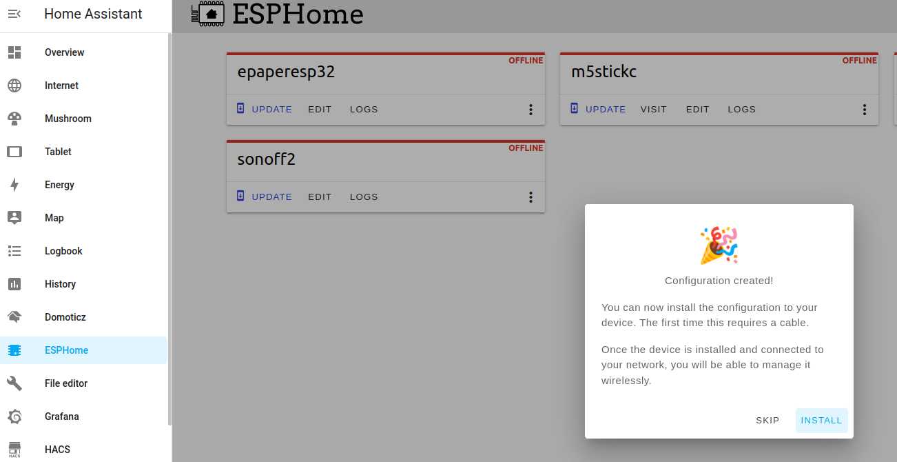
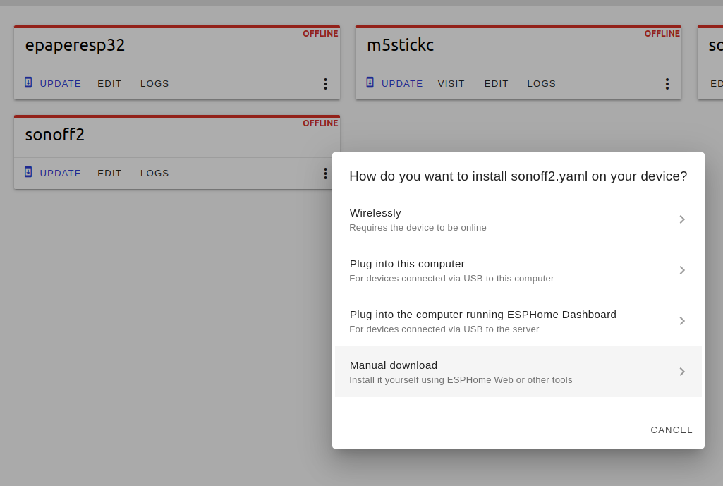
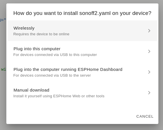
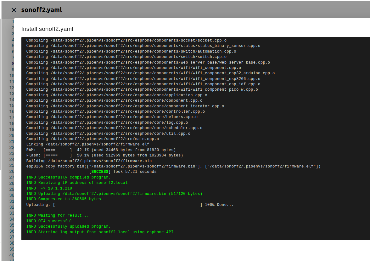
Press install and select manual download
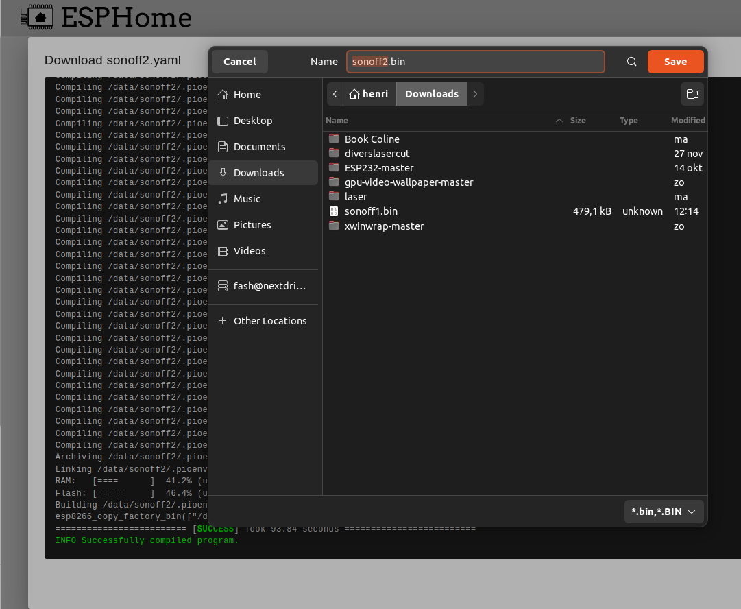
Above will compile a binary for the Sonoff device.
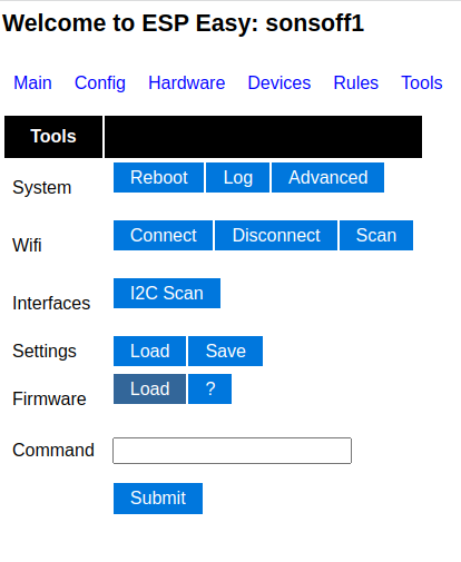
Go back to your Sonoff interface and go to the tools tab. We can reflash the device without connecting this with wires to our computer.
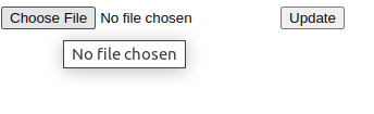
Press Firmware load and select your downloaded binary
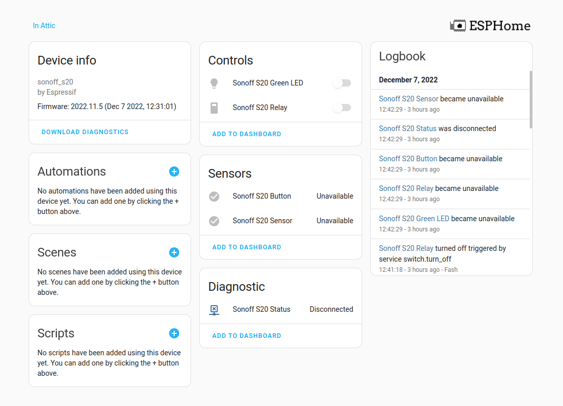
Back in HA it should say “online”
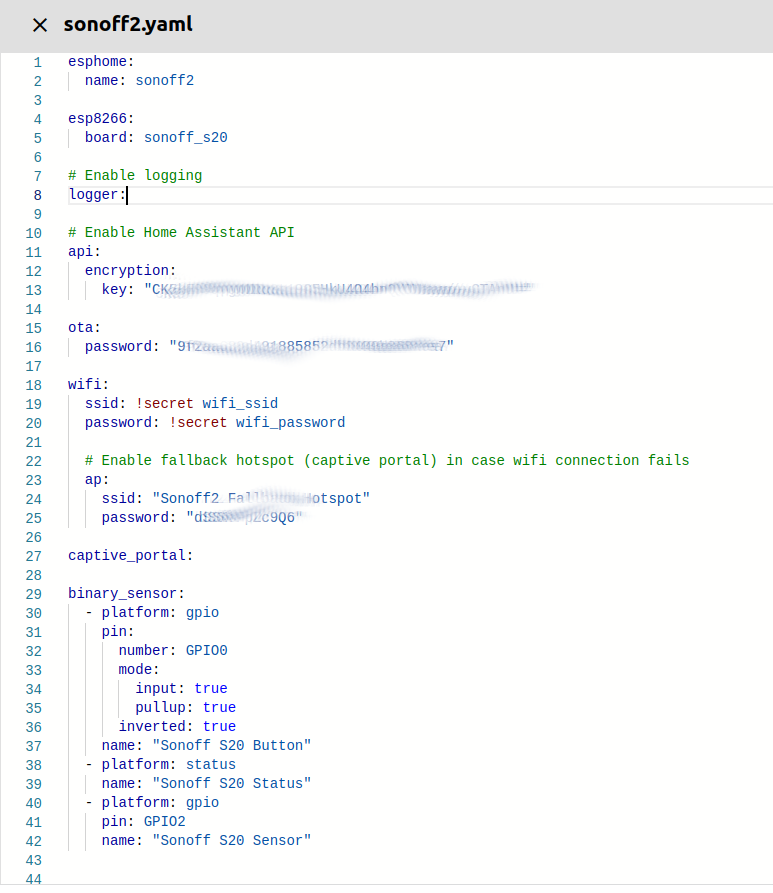
Pressing edit gives us a config page. Nothing works .. yet We need to add some yaml entries. ( use https://esphome.io/devices/sonoff_s20.html )
binary_sensor:
  - platform: gpio
    pin:
      number: GPIO0
      mode:
        input: true
        pullup: true
      inverted: true
    name: "Sonoff S20 Button"
  - platform: status
    name: "Sonoff S20 Status"
  - platform: gpio
    pin: GPIO2
    name: "Sonoff S20 Sensor"


switch:
  - platform: gpio
    name: "Sonoff S20 Relay"
    pin: GPIO12

output:
  # Register the green LED as a dimmable output ....
  - platform: esp8266_pwm
    id: s20_green_led
    pin:
      number: GPIO13
      inverted: true

light:
  # ... and then make a light out of it.
  - platform: monochromatic
    name: "Sonoff S20 Green LED"
    output: s20_green_led
BeforeAfter
Now press install
Now we can use wirelessly to upload the config
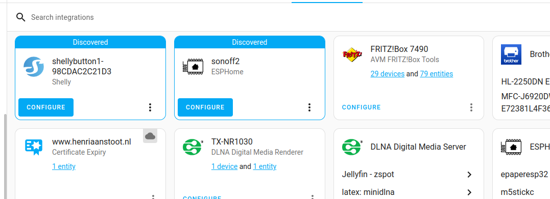
After this the device can be discovered by HA
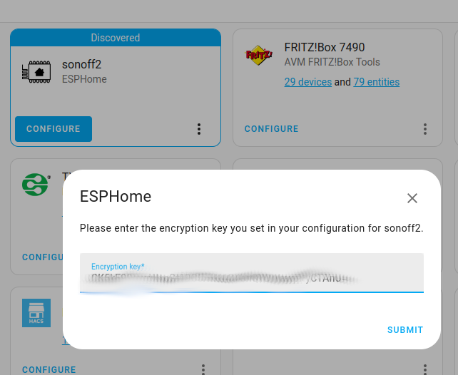
Click add, and use the encryption key found in the yaml config to add
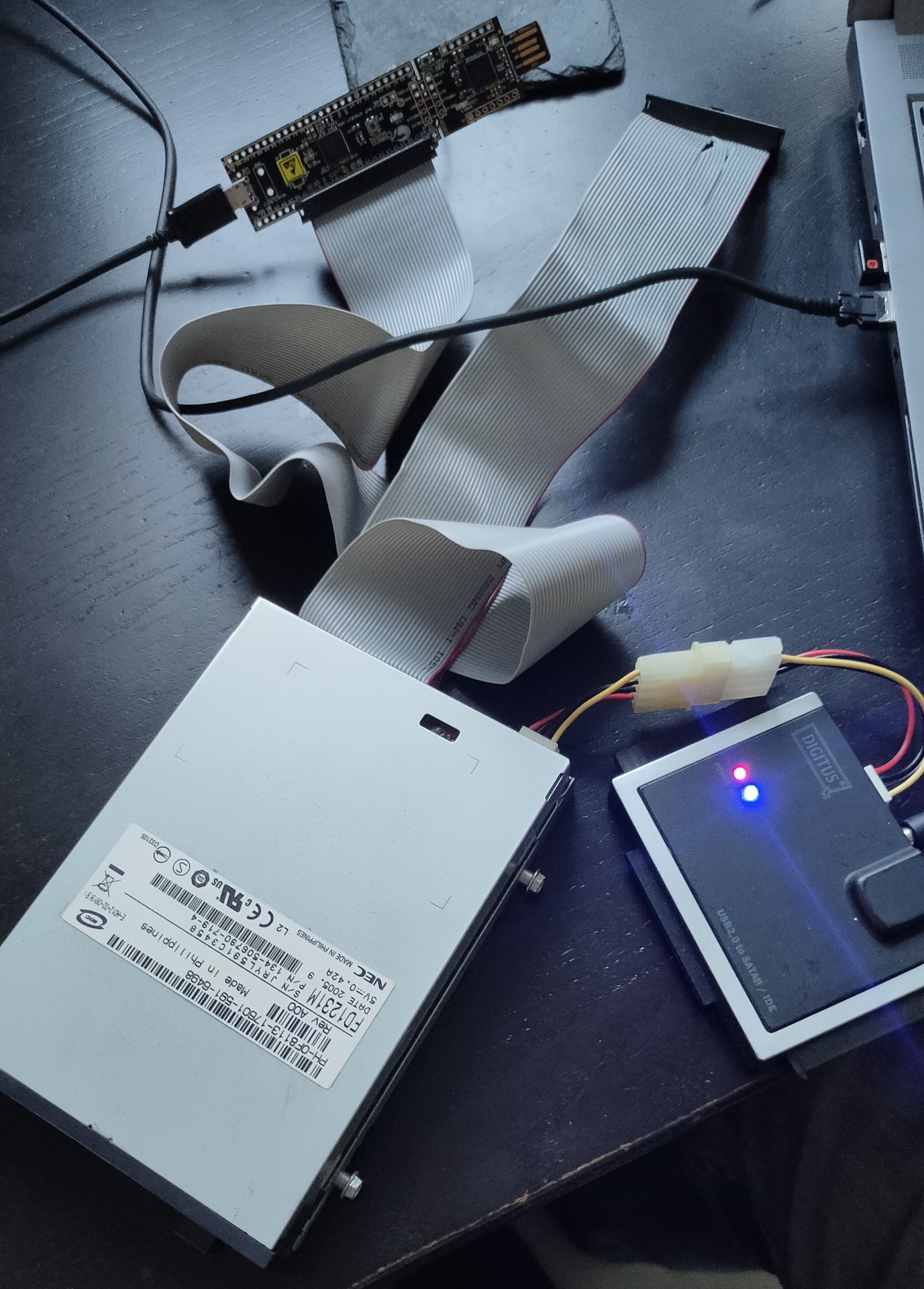
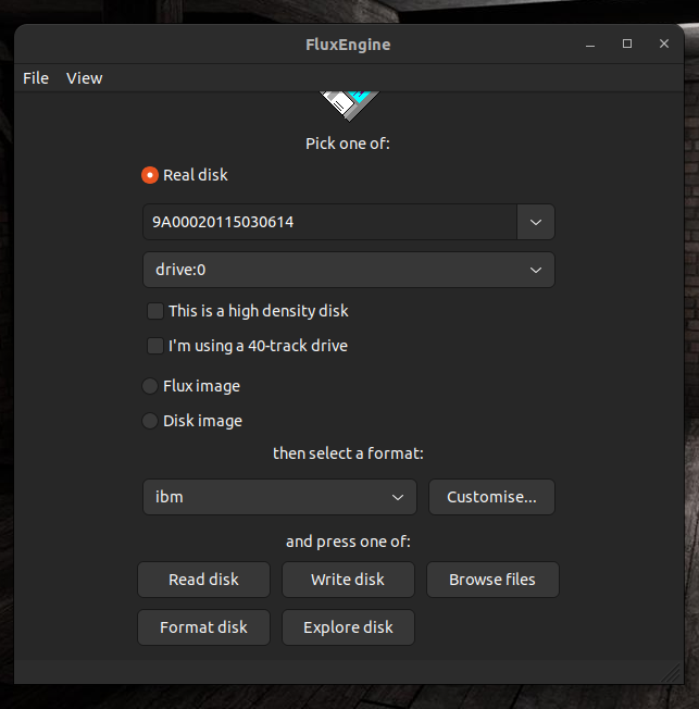
And found this! The fluxengine https://github.com/davidgiven/fluxengine
An open source project using a small controller board. “Flashing” some software on the board and soldering a pinheader was easy. When connecting a flat cable and a floppy drive, you end up with a device which can read many formats. Including dos 1.44/720 and amiga.
Nice package it came in
Using the power from a sata/ide harddisk adaptor
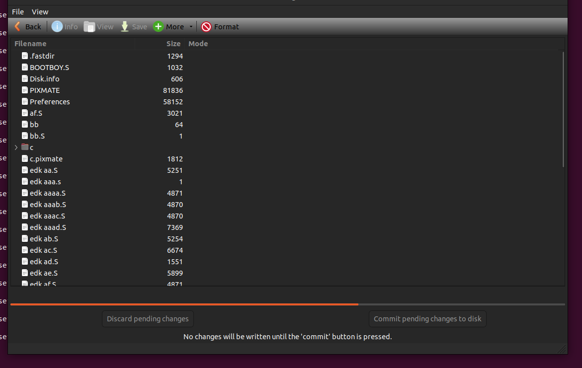
Reading and writing a MSDOS disk, no problem. Imaging an amiga disk .. easy!
You need to compile some software, but it was well documented
I have several ip cameras which monitor movement in and around our home.
I’m using Zoneminder and other home automation systems but i want to scan through a bunch of files uploaded by the security cameras to my secondary fileserver.
So what is interesting?
Major movement compared to a base image
Movement compared to a previous uploaded image
Setting a threshold when to output information (note the 65% mark)
Looking at the output we see: At 76% of the captured images (image 1438) the threshold was above 3000 and the minus gives us the information of the difference between this image and the previous, the X marks the difference between current image and the baseline. | percent | image number | filename | difference | graphbar
Bash script:
#!/bin/bash
threshold=3000
baseline=$( ls  SDAlarm*jpg | head -1)
previous=$( ls  SDAlarm*jpg | head -1)
total=$( ls *.jpg |wc -l)
echo "Number of files : $total"
nr=1
ls *jpg | while read; do
graph="....................................................................................................."
diff=$(compare -verbose -metric MAE $baseline $REPLY /dev/null  2>&1 | grep all | awk '{ print $2 }' | cut -f1 -d. )
prevdiff=$(compare -verbose -metric MAE $previous $REPLY /dev/null  2>&1 | grep all | awk '{ print $2 }' | cut -f1 -d. )
line=$( echo "100 / $total * $nr" | bc -l | cut -f1 -d.)
line=$(( $line + 1))
#echo -n "$line | $nr | $REPLY | "
#echo $diff
draw1=$(( $diff / 100 + 1))
draw2=$(( $prevdiff / 100 + 1))
graph=$(echo $graph | sed "s/./X/$draw1")
graph=$(echo $graph | sed "s/./-/$draw2")
if [ $diff -gt $threshold ] ; then
printf "| %4s %% | %3s | %30s | %5s | %102s \n" $line  $nr $REPLY $diff $graph
fi
nr=$(( $nr +1 ))
previous=$REPLY
done
Want to see only difference with previous image?
change:
if [ $diff -gt $threshold ] ; then into if [ $prevdiff -gt $threshold ] ; then
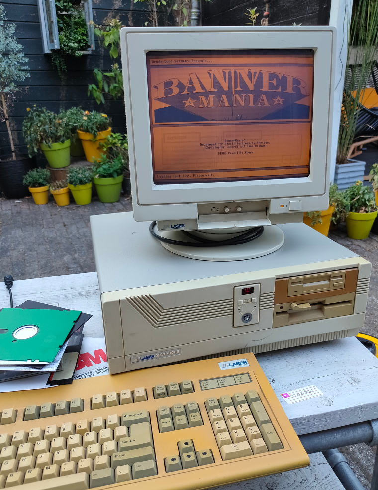
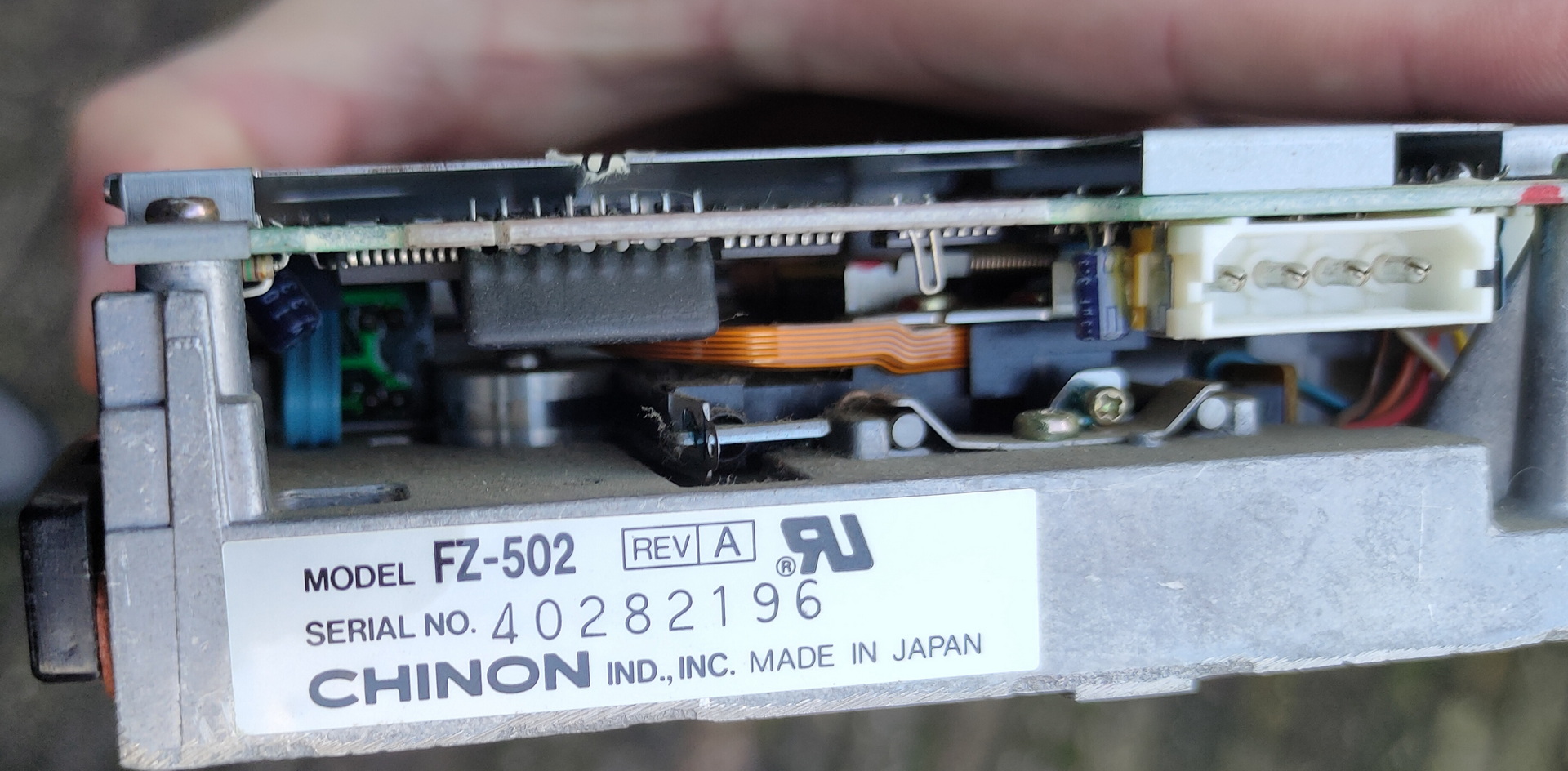
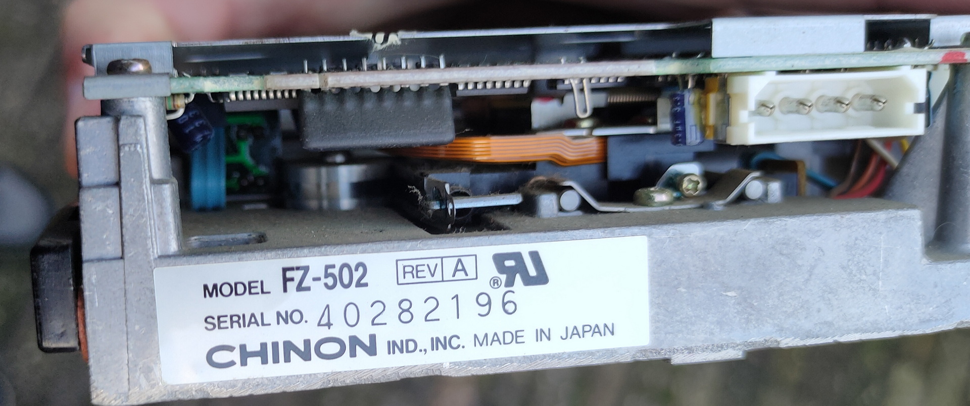
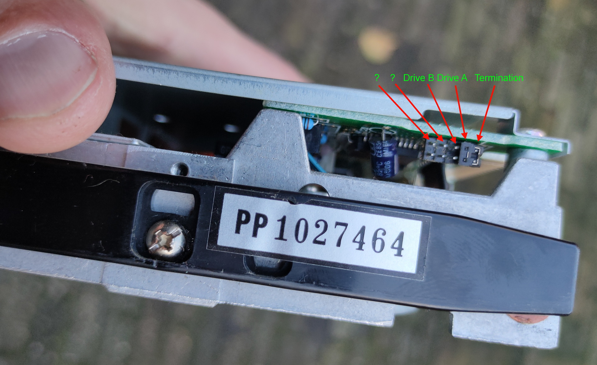
I bought a XT Laser/3 a while ago. And i wanted to get my old programs running on it again.
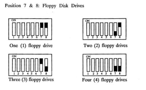
One of the disk i found was a 5.25 inch boot disk which should contain a boot demo i’ve made in the past with Edk. But it is the secondary drive in this system. Those old machines lack a bios you can change. And change A: for B: for example. Some machines had a program which could alter boot settings. (not this one) So i was playing with jumpers and dipswitches on the motherboard. ( Drive select / Termination / drive before or after the twist in the flatcable. )
Dipswitches on the motherboard
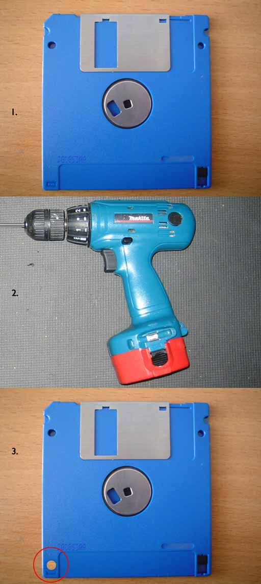
Wellll leave the boot order for now, i needed to get software on the machine using floppy’s. I could not find empty HD disks (1.44MB which i wanted to use) So i took a DD disk and a drill ..
(Image from the internet)
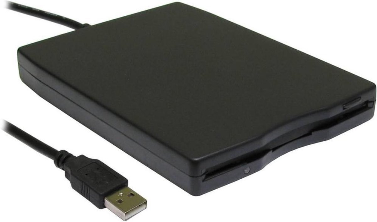
I bought an external usb floppy drive.
Now i have everything to get my programs on the msdos machine.
EXCEPT ….
Diskette didn’t work in the drives. So i bought new old stock diskettes online.
Now i have everything
WRONG again
Formatted 1.44 disk in USBfloppy drive .. OK Read in 3.5 drive on the MSDOS machine .. NOT OK Check drive in MSDOS machine .. is 1.44MB .. OK … check floppy controller in MSDOS machine .. NOT OKAY (720kb is 300kbits per second and 1.44 HD 500kbits per second) So i’m limited to 720kb due to the controller ..
Can the USB Floppy drive read/write 720kb disks .. NO! ( A cheap series made with drives only supporting HD disks )
Alternatives? .. Serial maybe, there is Norton Commander on the MSDOS machine so i could use “link”
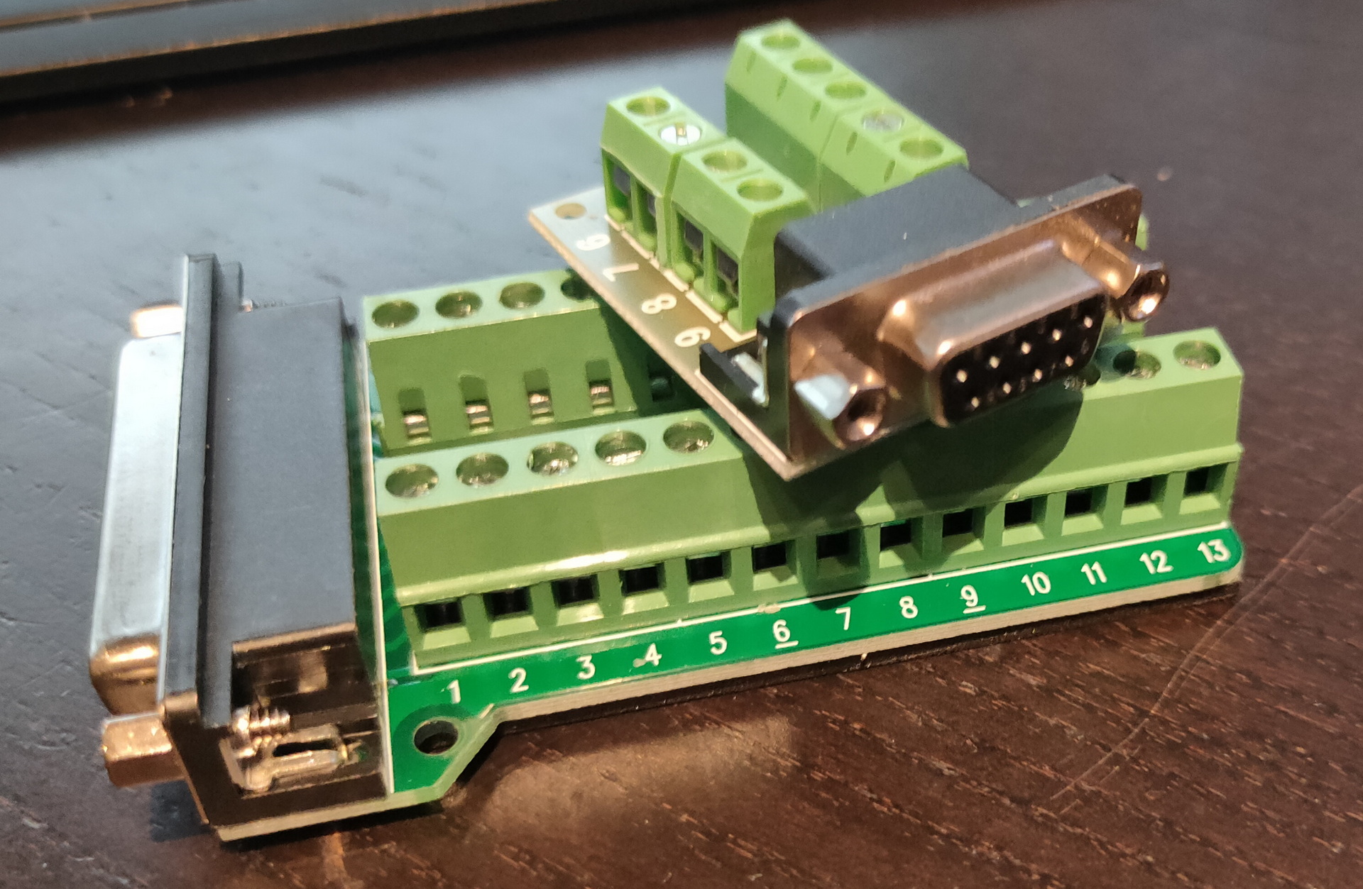
Do i still have a USB-RS232 sub-d cable ? YES! Nullmodem cable? NO Make a null modem cable .. i’ve made those before .. BUT no sub-d connectors.
I’ve been throwing away too much in the past.
Now i have to buy those things again:
VGA – 8bit ISA – have 2 now Floppy drive – have one for 1.44 8bit soundblaster compatible – TODO Nullmodem – well i’ve bought connectors for those
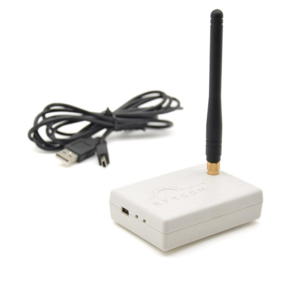
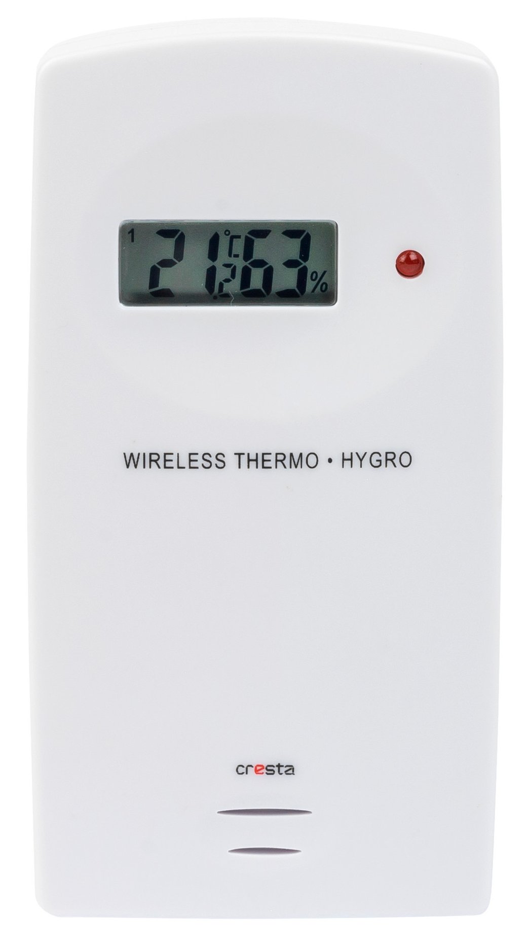
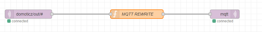
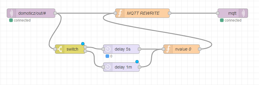
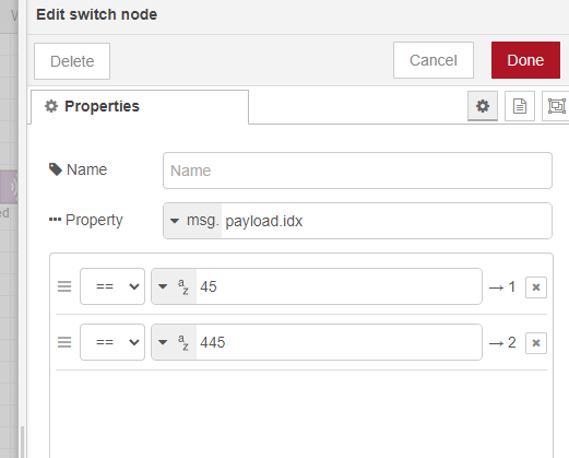
I’m using domoticz as a 433->mqtt bridge, and some virtual devices i can toggle with curl (bash scripts)
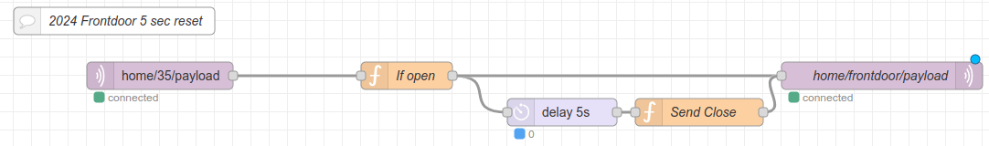
I needed to make a custom 433 door sensor in Home Assistant with toggles to OFF after a few seconds. (There is NO off signal in this cheap sensor i’m using)
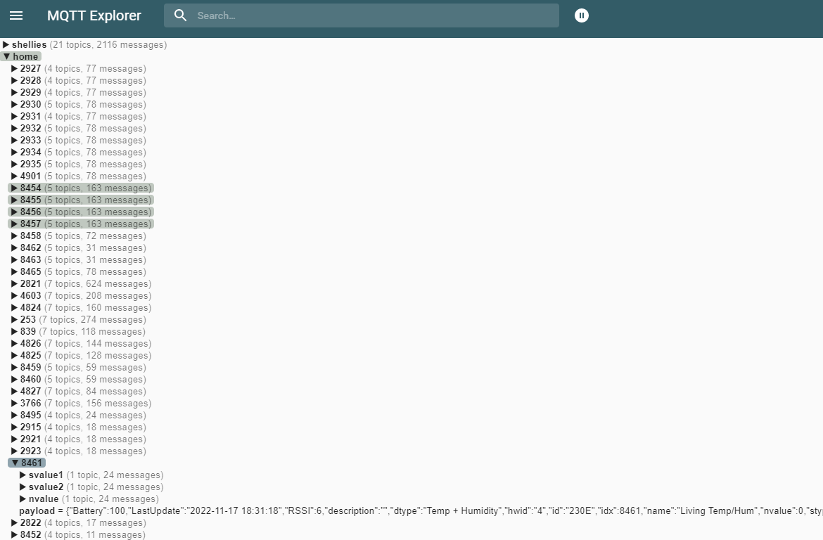
I’m changing the payload complete, to have a payload which matches the device class for door: (state with on/off) It was nvalue = 0/1
(Whenever the IDX changes, I only have to update this Nodered part) HA won’t notice the change.
var nvalue = msg.payload.nvalue;
msg.payload = {};
if(nvalue == 1)
{
msg.payload.state = "ON";
return msg;
}

AND after 5 seconds

msg.payload = {};
msg.payload.state = "OFF";
return msg;
download the package with used files and compilers from here: https://media.henriaanstoot.nl/assembly.tgz
extract with tar xzvf /tmp/assembly.tgz to a directory
start dosbox and mount the directory as C
mount c /path/assembly
Run “a line”, this a batchfile which starts the editor (qedit) When closing the file (esc – q menu) It will compile the assembly and write out a executable
This is the batchfile
@echo off
q %1.asm
cls
masm %1.asm;
link %1.obj;
exe2bin %1.exe %1.com
echo READY!
line assemblycode
    NAME lijnentrekroutine

.286

Code SEGMENT
    ASSUME CS:Code,DS:Code
org 100h
Start:
    mov ax,13h            ;set video mode
    int 10h

    mov bx,100
    mov cx,100
hiero:
    mov dx,0a000h
    mov es,dx
    mov ax,320
    mul cx
    add ax,bx
    mov di,ax
    mov al,2
    stosb
    inc bx
    inc bx
    inc cx
    cmp bx,150
    jnz hiero


    mov ah,8
    int 21h
    mov ax,3
    int 10h

    MOV AX,4C00h
    INT 21h

code ends
end start
While playing with MuseScore…. (Typesetting some scores for Pipes and Flute)
This came in: WOOOT
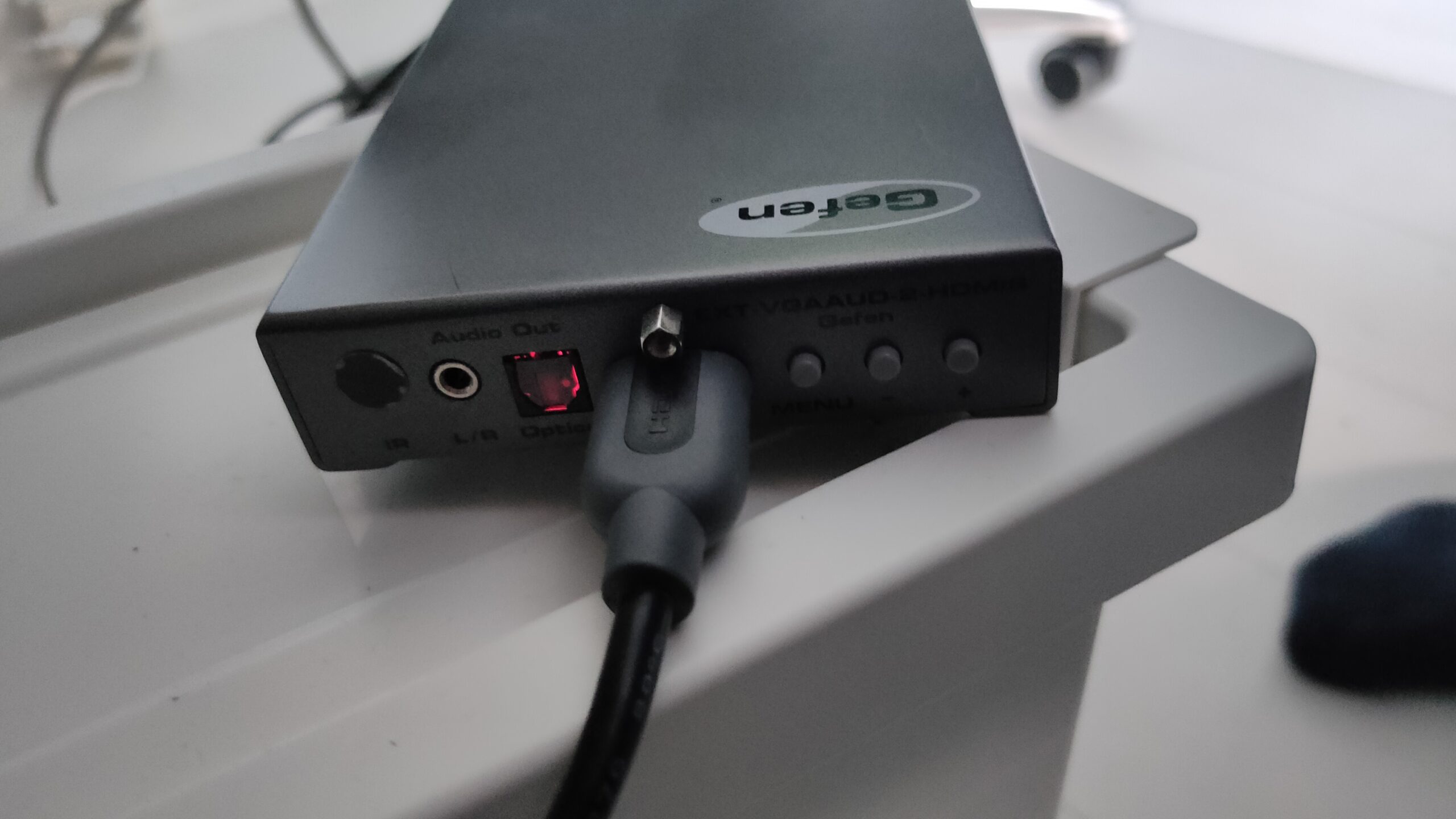
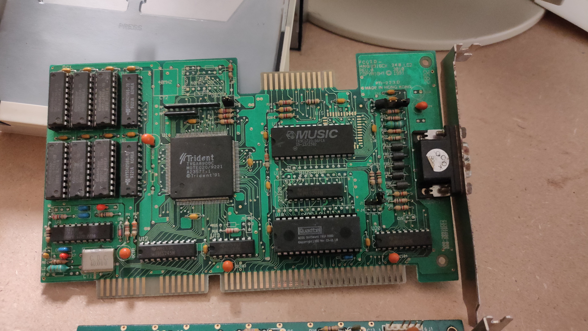
Trident 8900C (1024 x768 max 512Kb)
This is a Trident VGA card. While having a 16bit ISA connector, it can work in a 8bits ISA slot.
A while ago i bought a Laser XT/3, that’s the one my parents had. This is where i did a lot of assembly programming on. It’s a 8086 cpu, 640K and has a Hercules/CGA graphics card.
I found loads of assembly files and i want to see if i can get it running again. While some code was written for hercules, ( That’s the monochrome image you see in the example above ) and a few for EGA (4 colors).
Most of it was written for VGA. Probably on a later machine like a 80386?
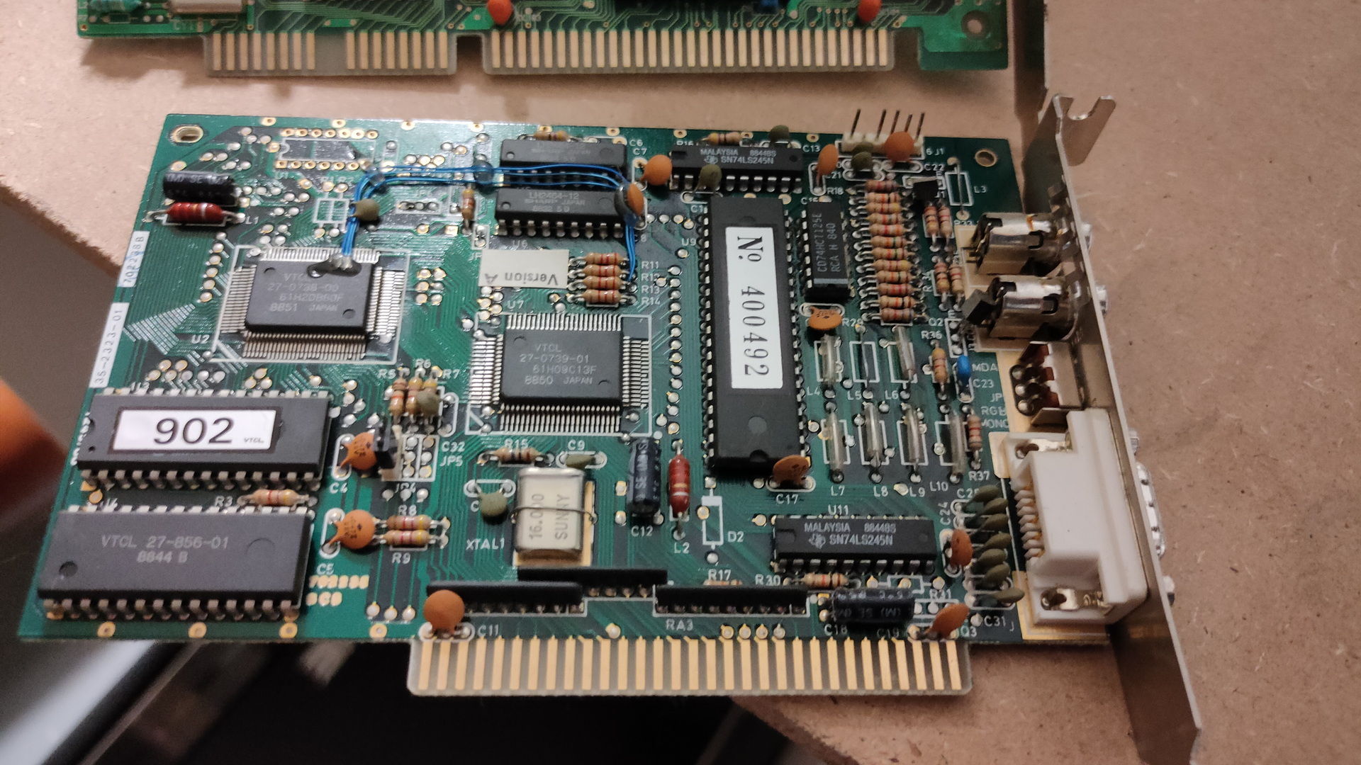
But i know there are vga cards for 8 bit msdos computers, and i found one. ( This one is even autodetect, so no jumpers to figure out)
So i’ve put this card in the machine, turned it on, and it works! I’ve got only 2 examples living on the harddisk of the machine, both black and white … 🙂 I have to search for interesting code in hundreds of files.
Some friends of mine, picture was taken from an amiga genlock digitizerThe intro pages of a “amiga emulator” WHERE is the rest??? (end is a cga starfield demo)
And a boot demo, which was able to start from a bootsector, went into a graphic mode and ran a demo with sound. Edk wrote a sector loader for this. I have some 5.25 inch floppy disks, labelled boot demo. So i wanted to try this today … I needed to change the boot order, so i went online to search for jumper settings.
I see a led when it tries to boot, but my disks are probably formatted 720Kb instead of 360Kb, which this drive is.
So …. TODO!
Find a 720Kb floppy drive (5.25 inch), and sort through my code! There is a 8bit soundblaster compatible soundcard that i bidding on online, hopefully i’ll get it
Assembly and modes
I wasn’t sure how to sort the assembly code into Hercules and VGA compatible, but i used this table (There are also extended modes for higher resolutions)
mode 0x00
text 40×25 gray
mode 0x01
text 40×25 16 colors
mode 0x02
text 80×25
mode 0x03
text 80×25 16 color
mode 0x04
graphics mode (CGA) 320×200
mode 0x05
graphics mode (CGA) 320×200
mode 0x06
graphics mode (CGA) 640×200 (B/W)
mode 0x07
text 80×25 Hercules
mode 0x0F
graphics mode 640×350? gray
mode 0x10
graphics mode 640×350?
mode 0x11
graphics vga 2 colors
mode 0x12
graphics vga 16 colors
mode 0x13
graphics 320×200 256 colors
# Set VGA mode
    mov ax,13h
    int 10h         ;screen 320x200 256 colours

# Exit VGA mode
    mov ax,3
    int 10h         ;screen  80x25 text
    mov ax,4c00h
    int 21h         ;back to DOS
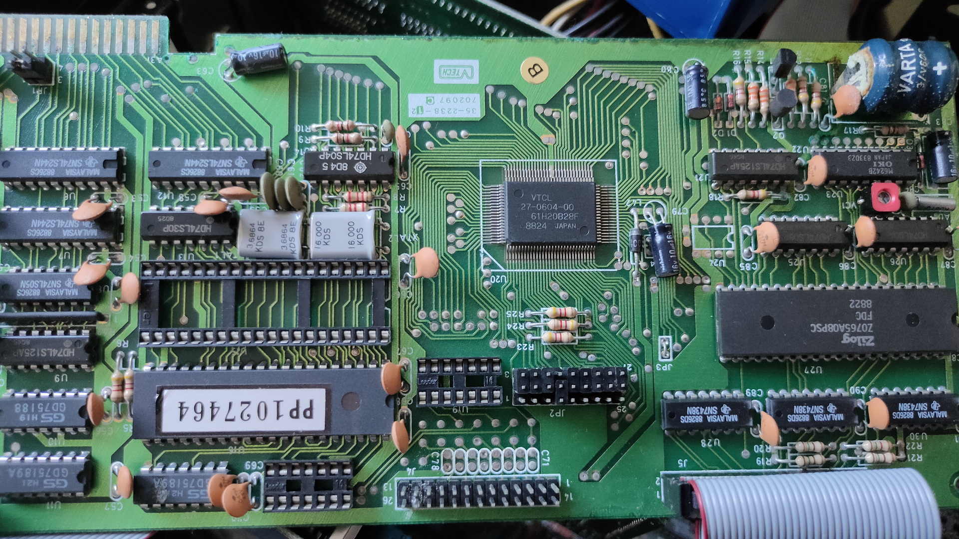
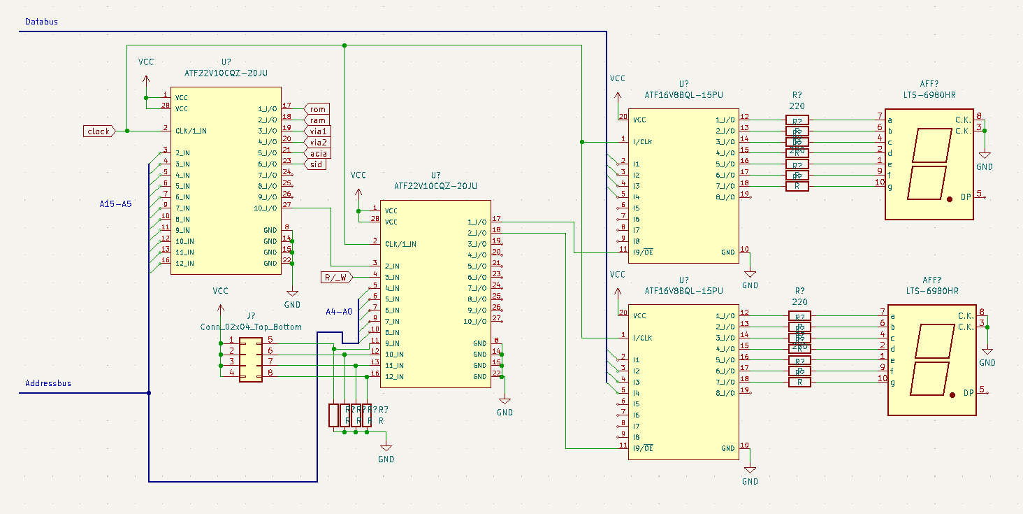
Sometimes when i’m writing code i want to know what’s happening. For example when i’m working on the display, there is maybe no output. With the above example i can write to address $01F0 (example address), and it will display on the 7 Segment displays.
Upperleft PLD is my address decoder, which has been running for a while now.
Secondary PLD adds the rest of the Addressbus lines, and gives me the opportunity to select in a range of 16 addresses, using jumpers/
The two smaller PLD’s latch the databus data when addressed. AND decodes a nibble to 7-Segment output for 0-9A-F. (There are apparently no chips available which do A-F)
I’m going to add the PLD code when everything works. Let me know if you like the idea.
Should be only a few Euro’s
"If something is worth doing, it's worth overdoing."