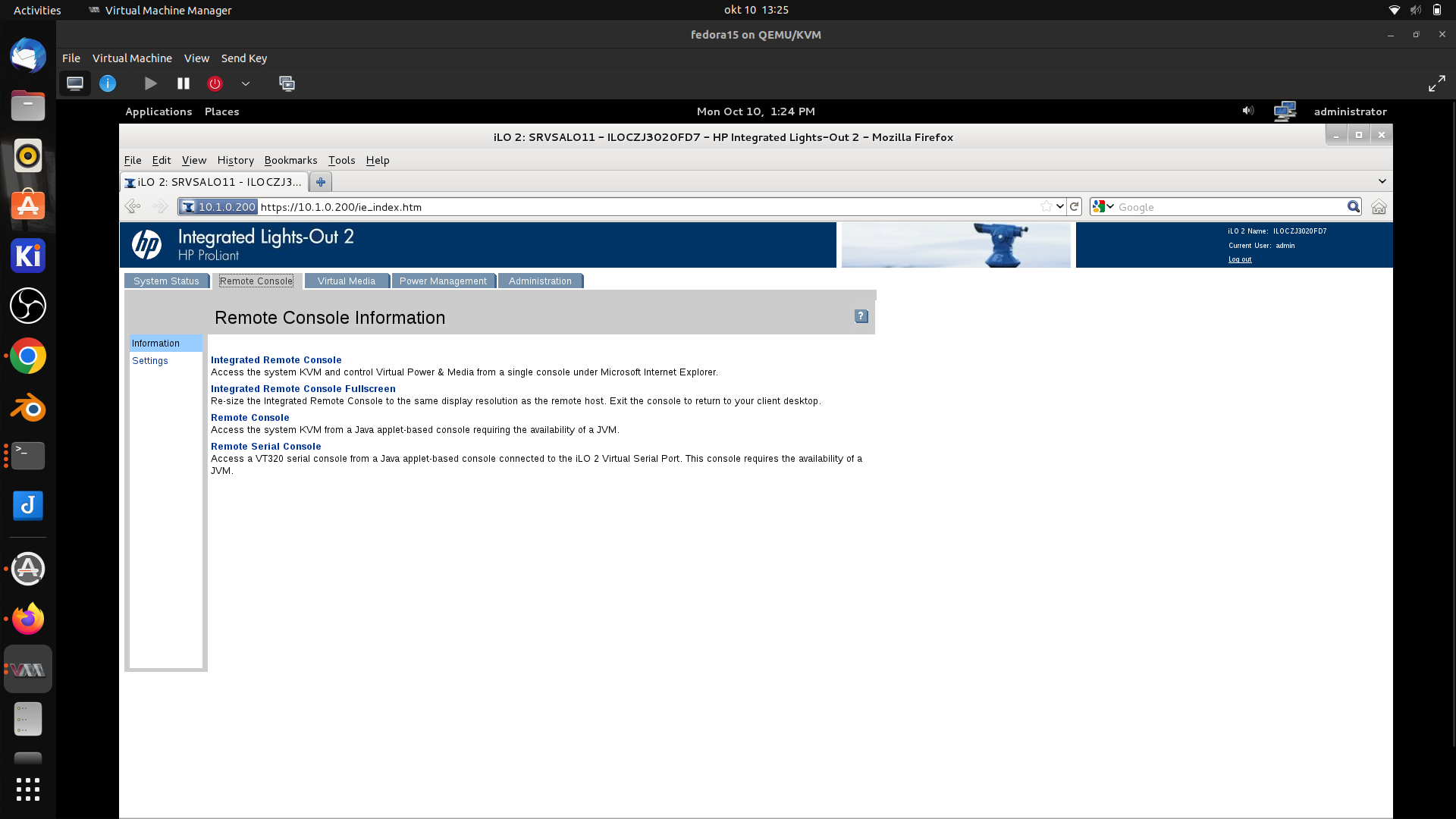
We bought some servers a while ago, but these have old ILO versions (2).
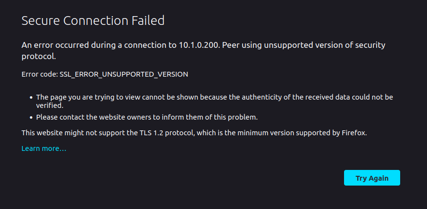
To manage these servers via ILO was no problem until modern browsers refuse to connect to these web services, because of TLS 1.0 issues.
So what i did was using a second user account on my workstation with a old (downloaded from a ESR archive) version firefox. To administer the ILO
wget https://ftp.mozilla.org/pub/firefox/releases/50.0/linux-x86_64/en-US/firefox-50.0.tar.bz2
extract in other users homedir

usage:
# ssh with X forwarding and start old version
ssh -X otheruser@localhost firefox/oldfirefox
While this was working for me on a debian based machine it didn’t work for my friend who was using Fedora on Wayland.
So i made a more generic solution which would work always. Also when working from windows.
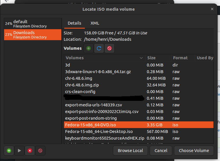
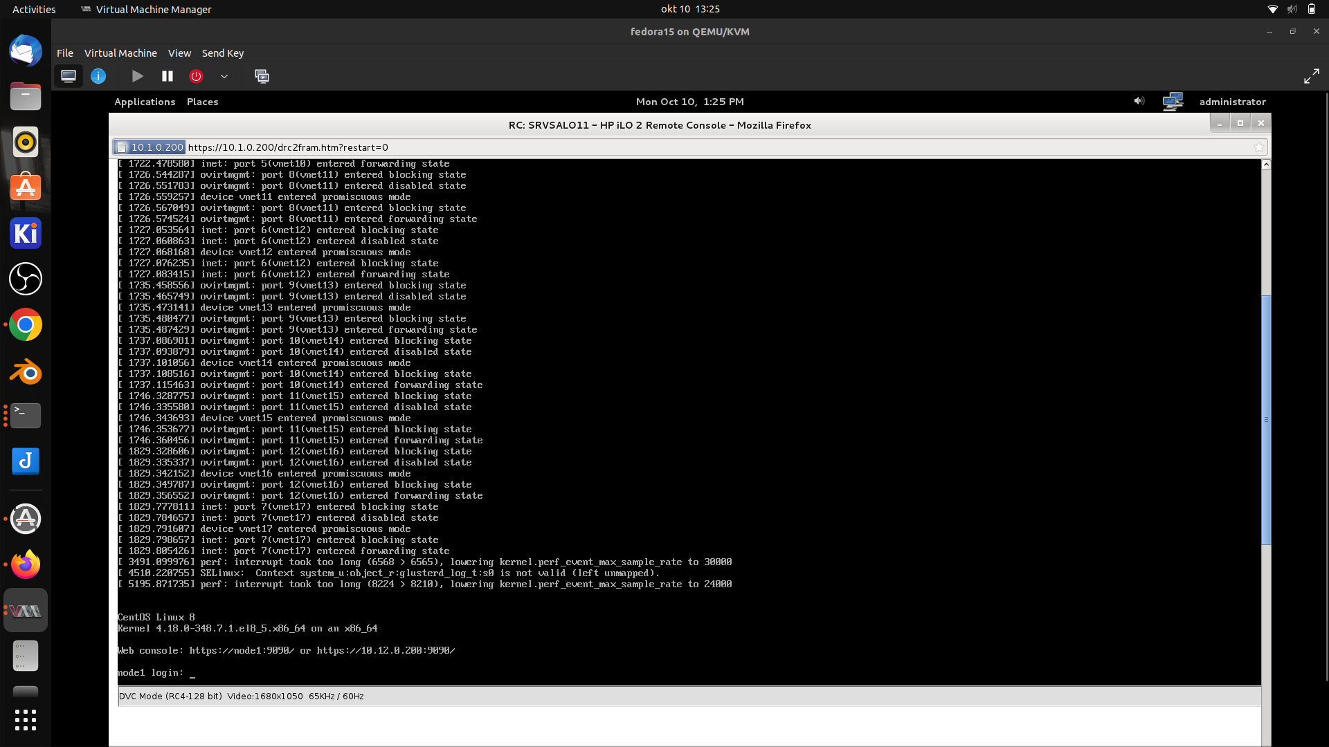
I downloaded a old Fedora version ISO. https://archives.fedoraproject.org/pub/archive/fedora/linux/releases/15/Fedora/x86_64/iso/ Using the DVD iso i knew the old JAVA was present.
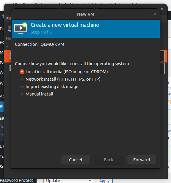
So i started virt-manager and created a new virtual machine
Select your downloaded Fedora 15 ISO
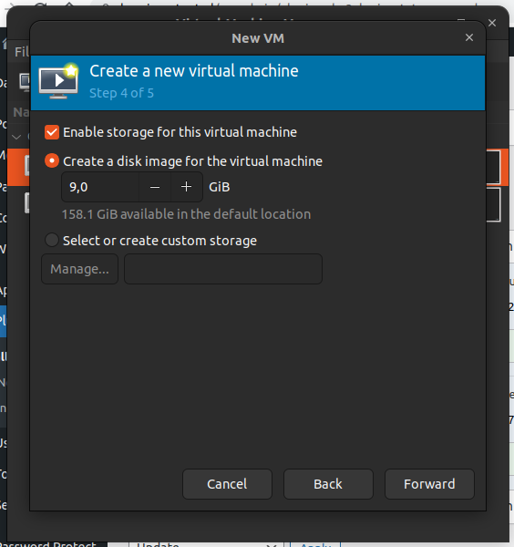
Where is the thin option?!??!
Create a disk image for the OS, don’t worry about the size we are going to shrink it to a minimum (thin provisioned)
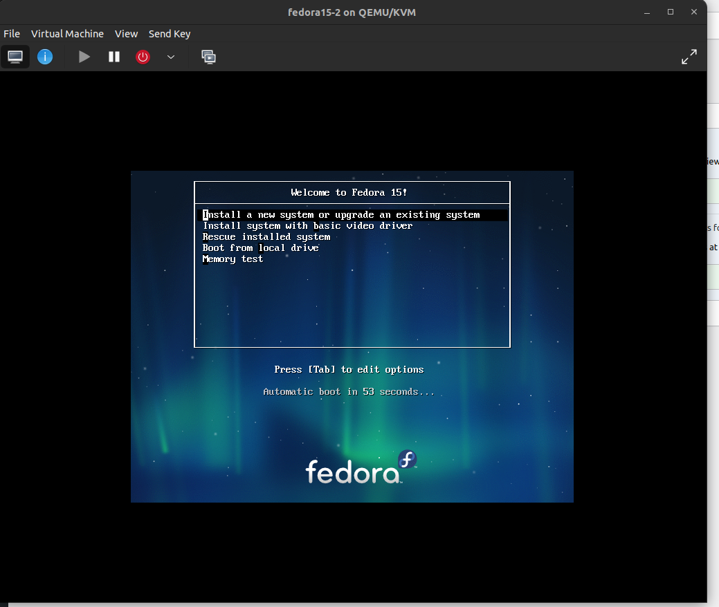
Booting from ISO
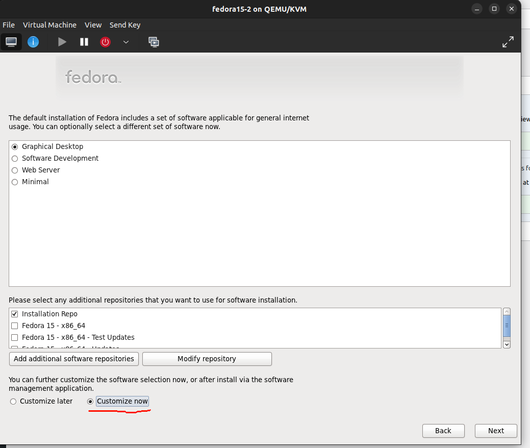
Do not forget to tick Customize now
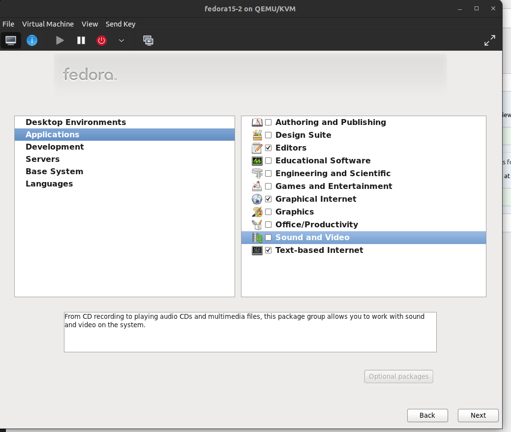
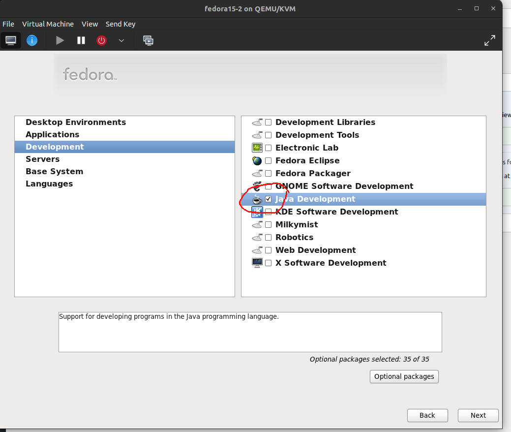
Disable all thats not needed! .. Only Gnome Graphical internet .. and JAVA
Create users, complete the install and reboot. Test your installation. Shutdown
sudo qemu-img info /var/lib/libvirt/images/fedora15.qcow2 When above gives you a RAW image, you need to convert from RAW to QCOW first. Mine showed a 9G qcow2 image .. far to large
I had a crash recently on one of my raspberry-pi’s .. SDcard failure, they are not made for a lot of write actions. In the past i’ve changed some images to read only and with a r/w overlay. Also tmp filesystems in memory .. all not ideal.
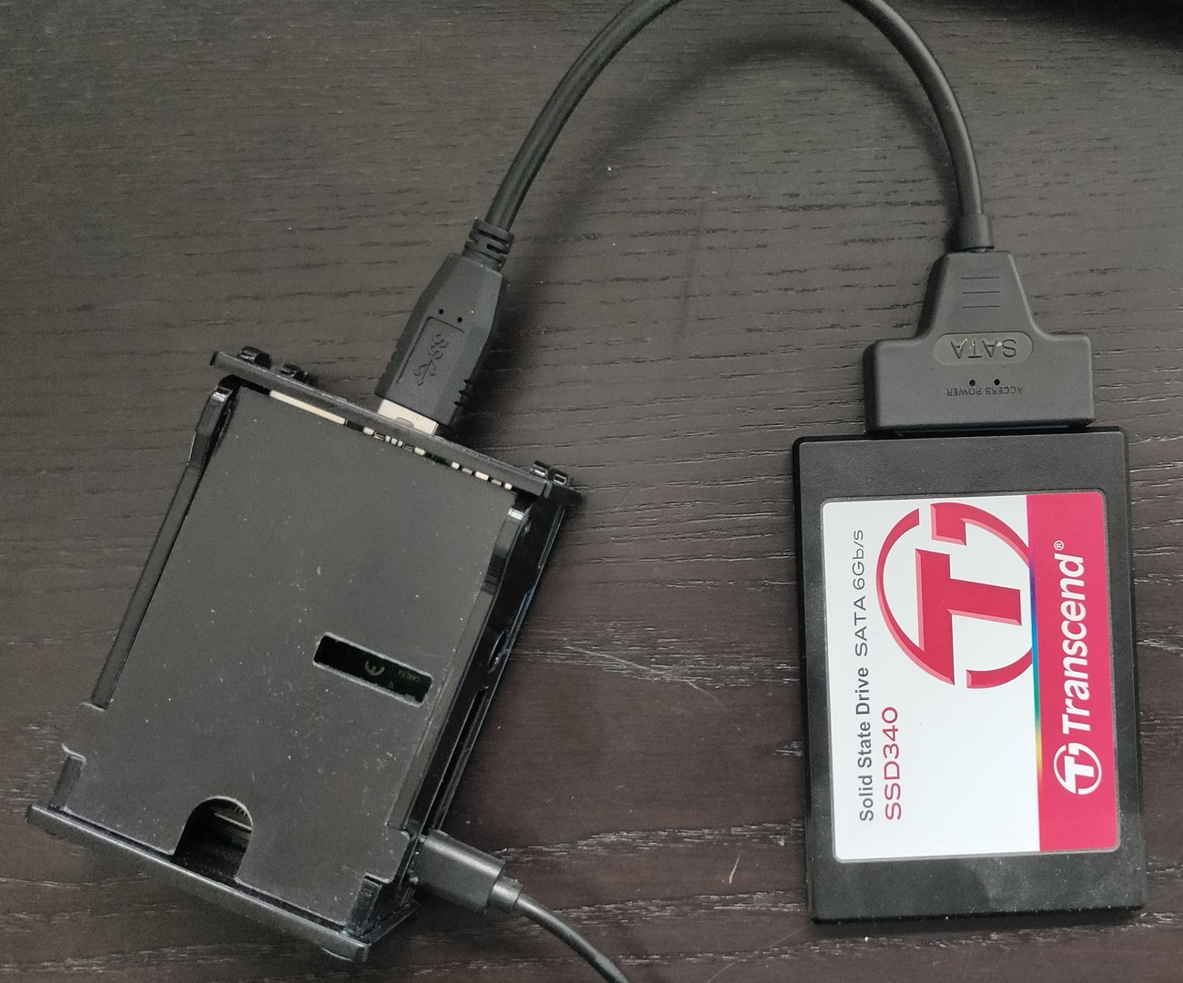
So i’ve started to make every RPi ssd bootable.
I’ve got several ssd already from other projects. Sata to USB adaptors are cheap, only a few euro’s.
Steps to take:
Download Raspberry Pi Imager tool
Choose OS > Misc Utility Images > Bootloader > USB Boot
Select storage and write to a temporary sd-card (Not needed any more after flashing for normal operations)
Boot USB with this Micro-SDcard .. i didn’t have a screen connected .. So i just waited a few minutes
While i was waiting i wrote a OS image to the SSD using the same imager tool
Choose OS > select sata/ssd drive
Change options (cog), enable ssh, choose hostname and set password
Write to drive
Remove sdcard from RPi attach ssd/sata and boot
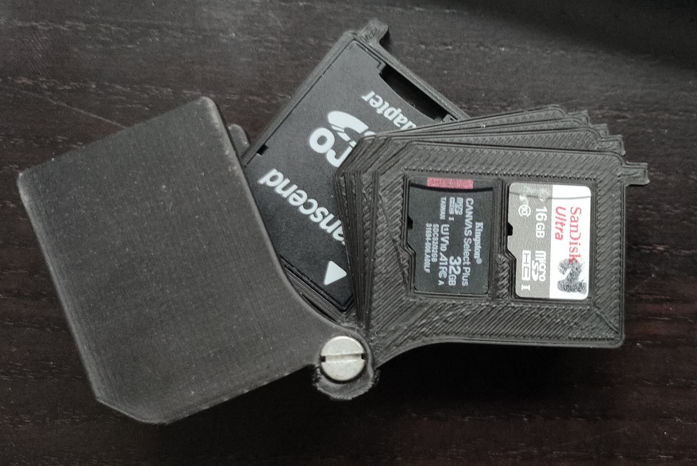
My 3D printed sdcard case, luckily there was still one in there (32GB kindda big, but it was only for temporary use .. 16GB was broken ..
So .. without attaching a screen or keyboard, just a network cable. I have a running OS on a RPi from SSD
Last year i made a script for a friend who wanted to detect visually if his garden sprinkler was on or off. A few days ago i saw someone who wanted to see if things where moving in his house. (didn’t trust his landlord i think) But he only had a dumb/simple/cheap camera .. so it had no motion detection.
I was thinking of my script, and could easily adapt it for this usage.
Most ipcams have somekind of URL/API you can use to capture a image. Some examples below
So using below script i can capture a image, compare it to the previous, and when it’s above a certain threshold sends a email.
#!/bin/bash
# Only uses wget and image-magick
treshhold=500
fuzzyness=20%
# CHANGE WEBCAM THINGY TO OWN URL AND CREDENTIALS
wget -q "http://webcamip/cgi-bin/api.cgi?cmd=Snap&channel=0&user=user&password=password" -O previous.jpg
while true;  do
wget -q "http://webcamip/cgi-bin/api.cgi?cmd=Snap&channel=0&user=user&password=password" -O current.jpg
value=$(compare -fuzz $fuzzyness previous.jpg current.jpg -metric mae diff.jpg 2>&1 | cut -f1 -d.)
if [ $value -gt $treshhold ] ; then
echo "ping $treshhold"
echo "Something moved" | mail -s "Movement" user@example.com -A diff.jpg
fi
# Comment below if you want to compare against a base line .. not previous image
cat current.jpg > previous.jpg
sleep 60
done
Example previous picture
Example current picture
I got mailed with result
Hints tips:
Use crop to detect only a part.

copy current.jpg to a second file
Use painting black a part and compair with different treshhold fuzzyness to get different hotspots.

Below detects RED, use above ide with crop to detect red/green/blue leds

compare -verbose -metric mae 1.jpg 2.jpg /tmp/1.diff
1.jpg JPEG 2560x1920 2560x1920+0+0 8-bit sRGB 248819B 0.050u 0:00.057
2.jpg JPEG 2560x1920 2560x1920+0+0 8-bit sRGB 248949B 0.030u 0:00.137
Image: 1.jpg
  Channel distortion: MAE
  Channel distortion: MAE
    red: 12517.5 (0.191005)
    green: 11967.1 (0.182607)
    blue: 12492.8 (0.190628)
    all: 12325.8 (0.18808)
1.jpg=>/tmp/1.diff JPEG 2560x1920 2560x1920+0+0 8-bit sRGB 1.19495MiB 1.470u 0:00.197
The goal of this project is to have a raspberry-pi with a screen wich shows network information. It wil be using a battery, touchscreen .. maybe some status leds. When debugging network issues we want to have information when/if/how a network port works on our switches.
It should show:
dhcp ip
gateway
can access internet?
speedtest
detect if vlan tagged network packets are present on the port?
icmp test
list of detected nearby hosts?
A long time ago i played with glade and C / Perl.
But i’d rather use python so i’m looking into glade/python combi for this little project.
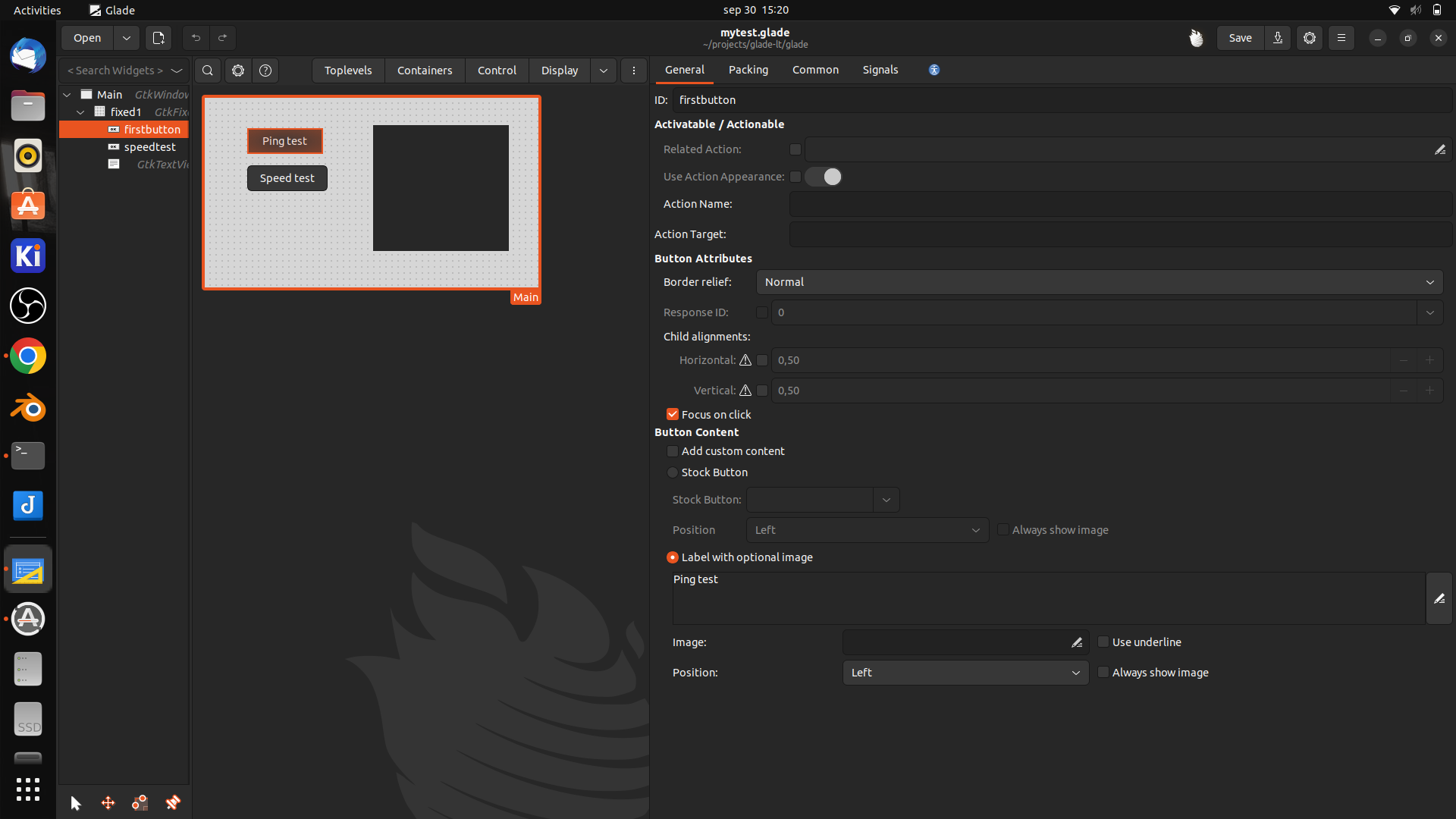
Glade is a gnome/GTK user interface RAD tool. (Rapid Application Development)
i’ve used zenity and yad before to create simple gui’s for bash scripts, these where only for quick and dirty solutions. (See other posts) Glade is a far better solution, but a little harder to use.
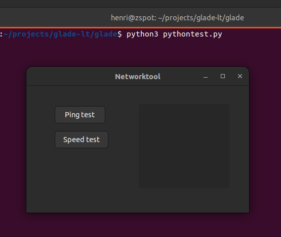
Below is a little framework i started with
Python script
import gi

gi.require_version("Gtk", "3.0")
from gi.repository import Gtk

class Handler:
    def onDestroy(self, *args):
        Gtk.main_quit()

    def on_firstbutton_clicked(self, button):
        print("Ping test")

builder = Gtk.Builder()
builder.add_from_file("mytest.glade")
builder.connect_signals(Handler())

window = builder.get_object("Main")
window.show_all()

Gtk.main()
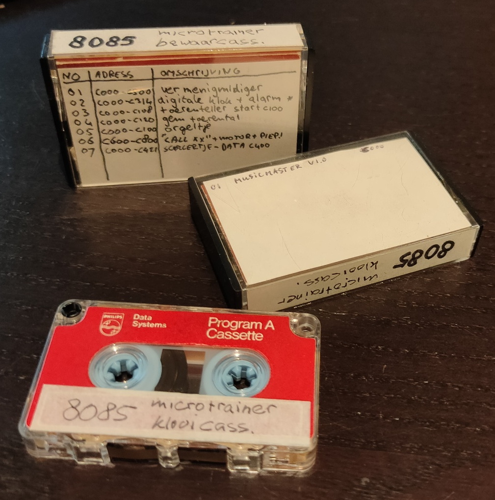
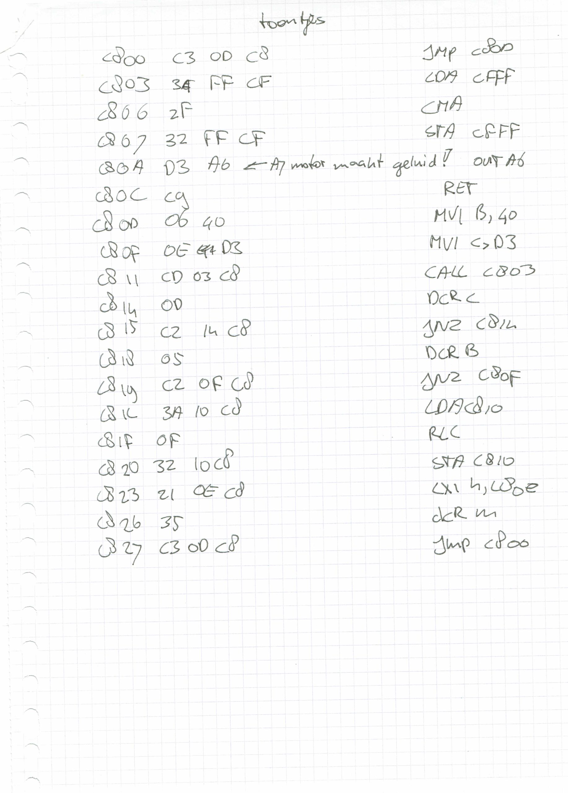
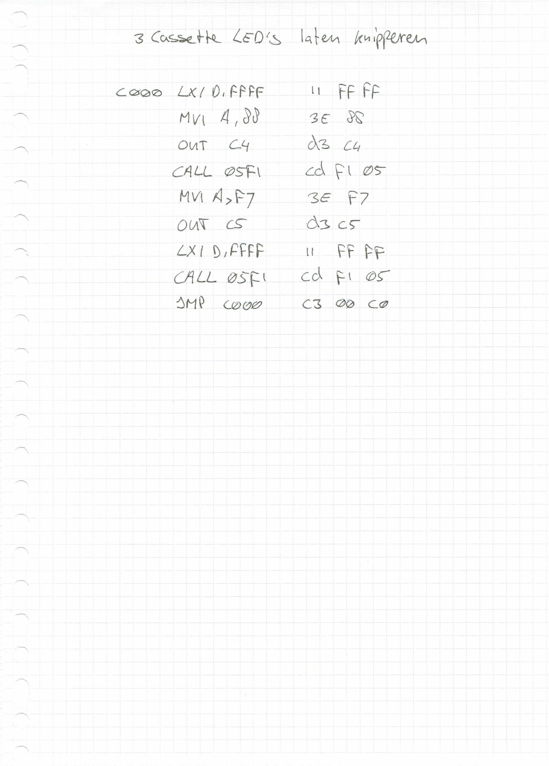
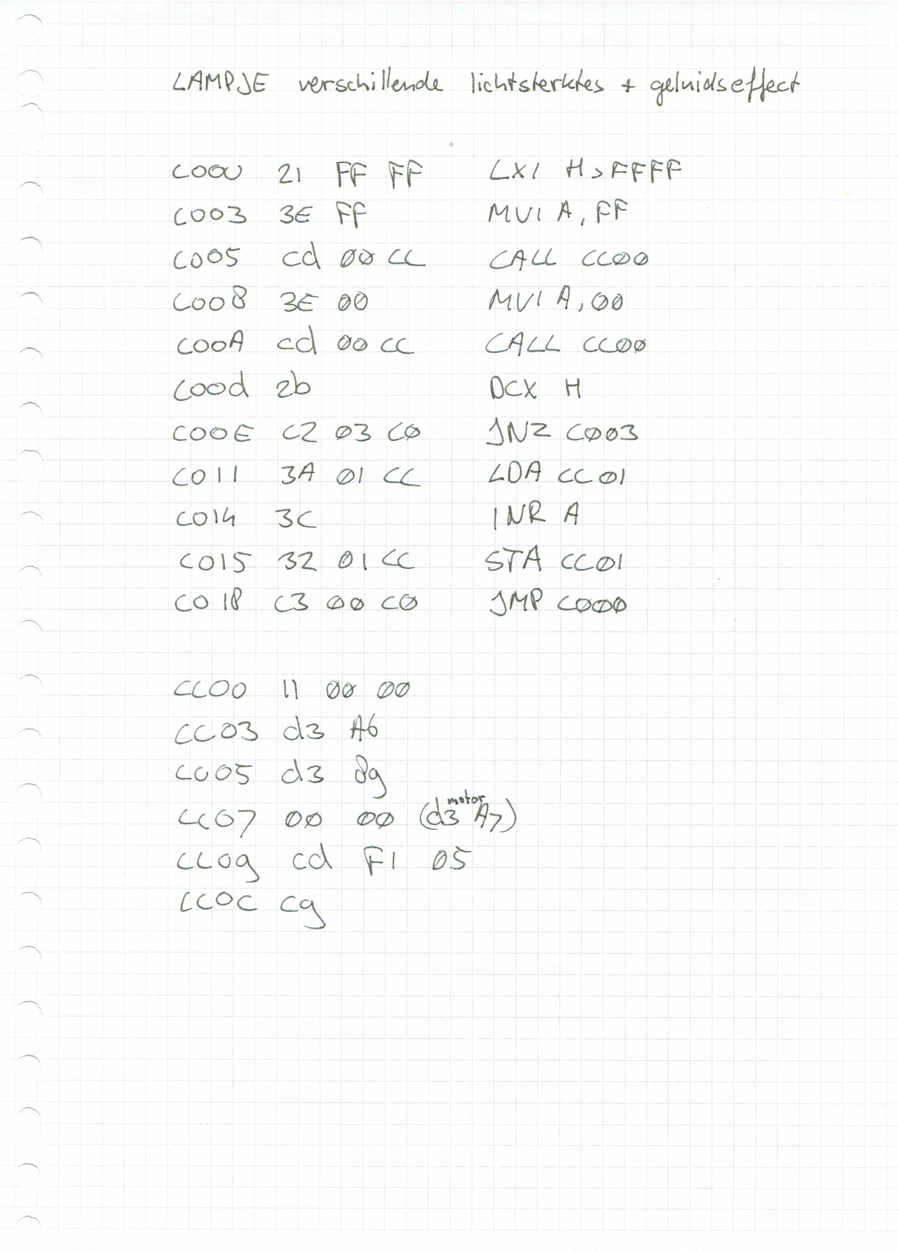
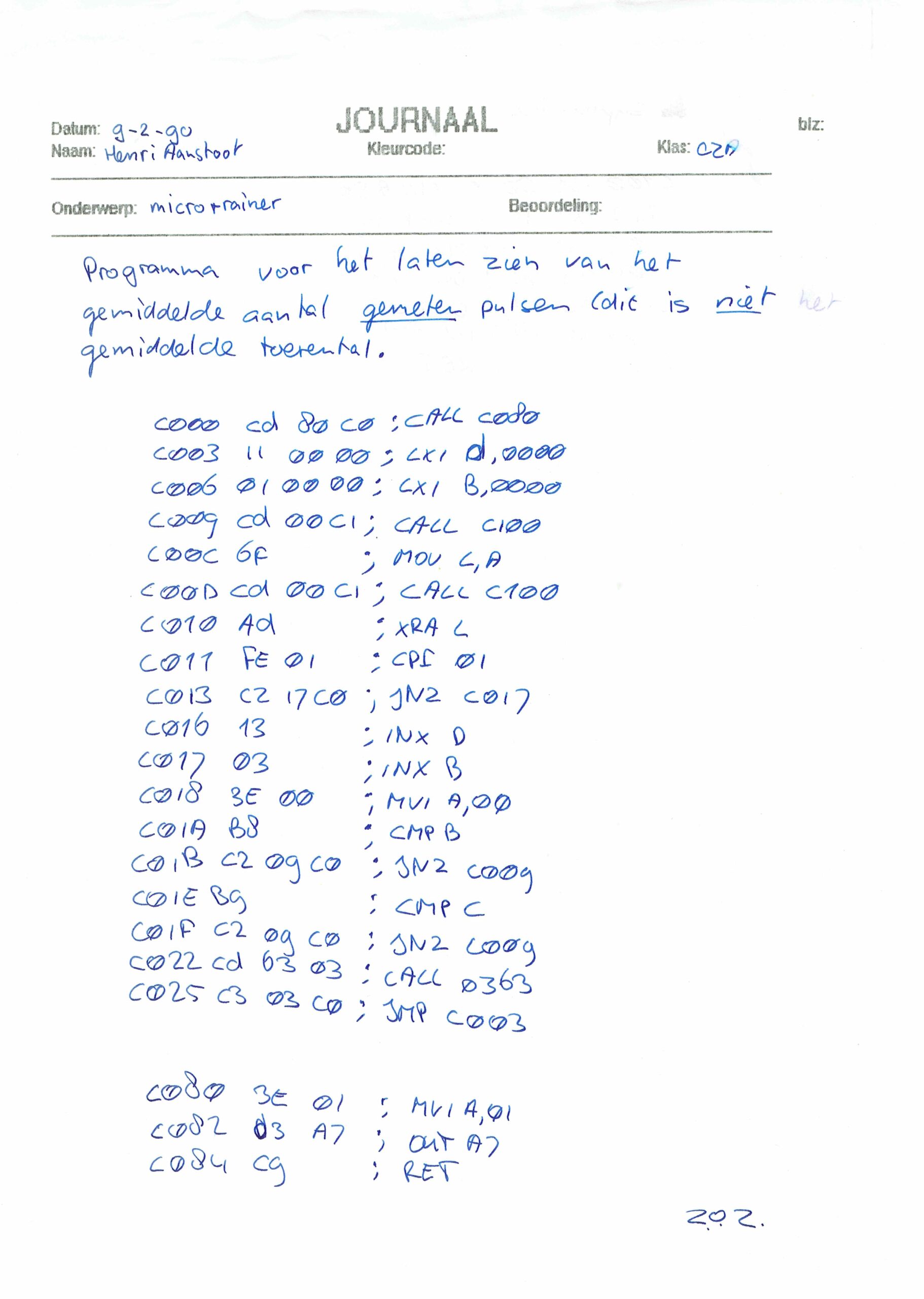
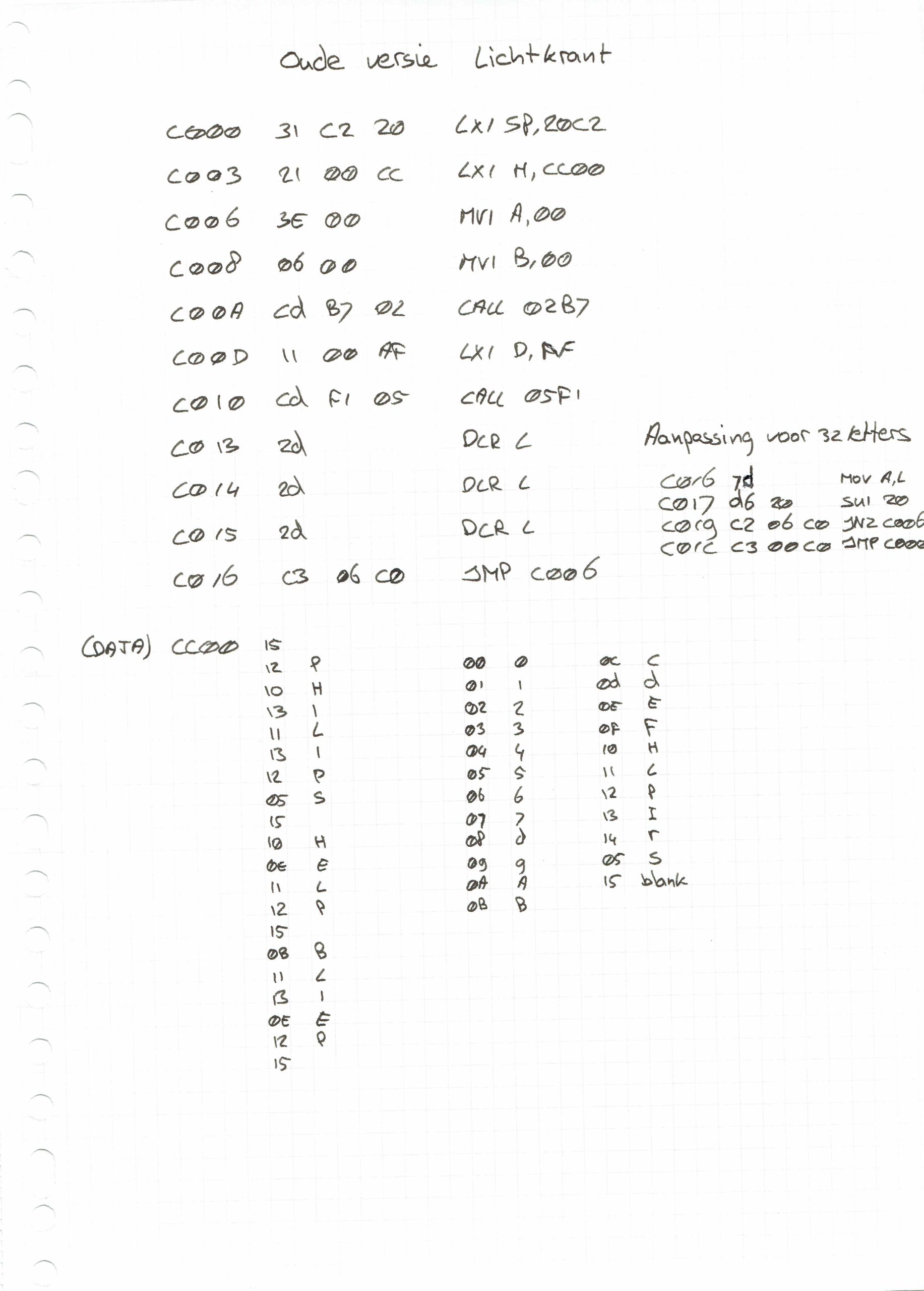
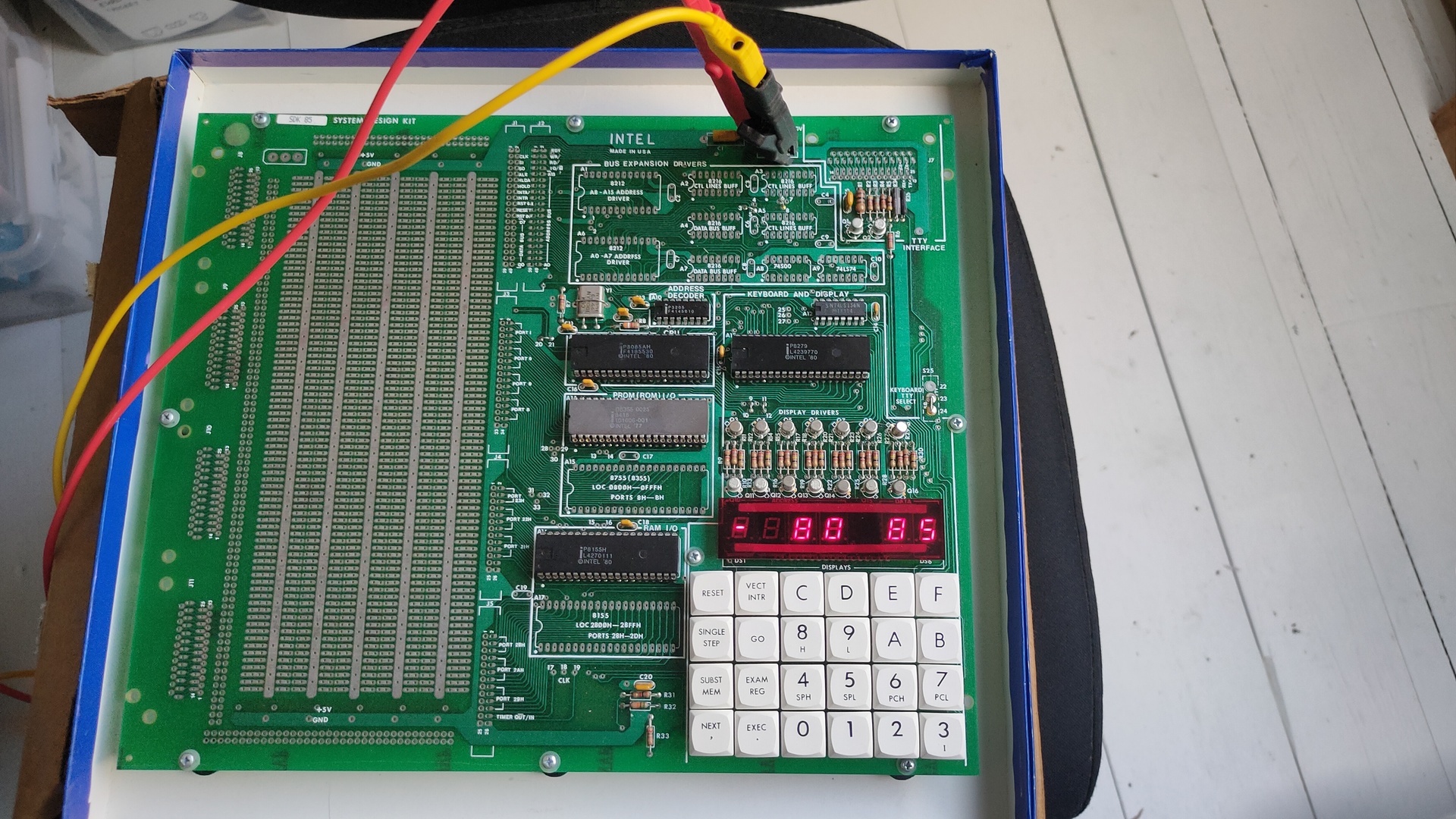
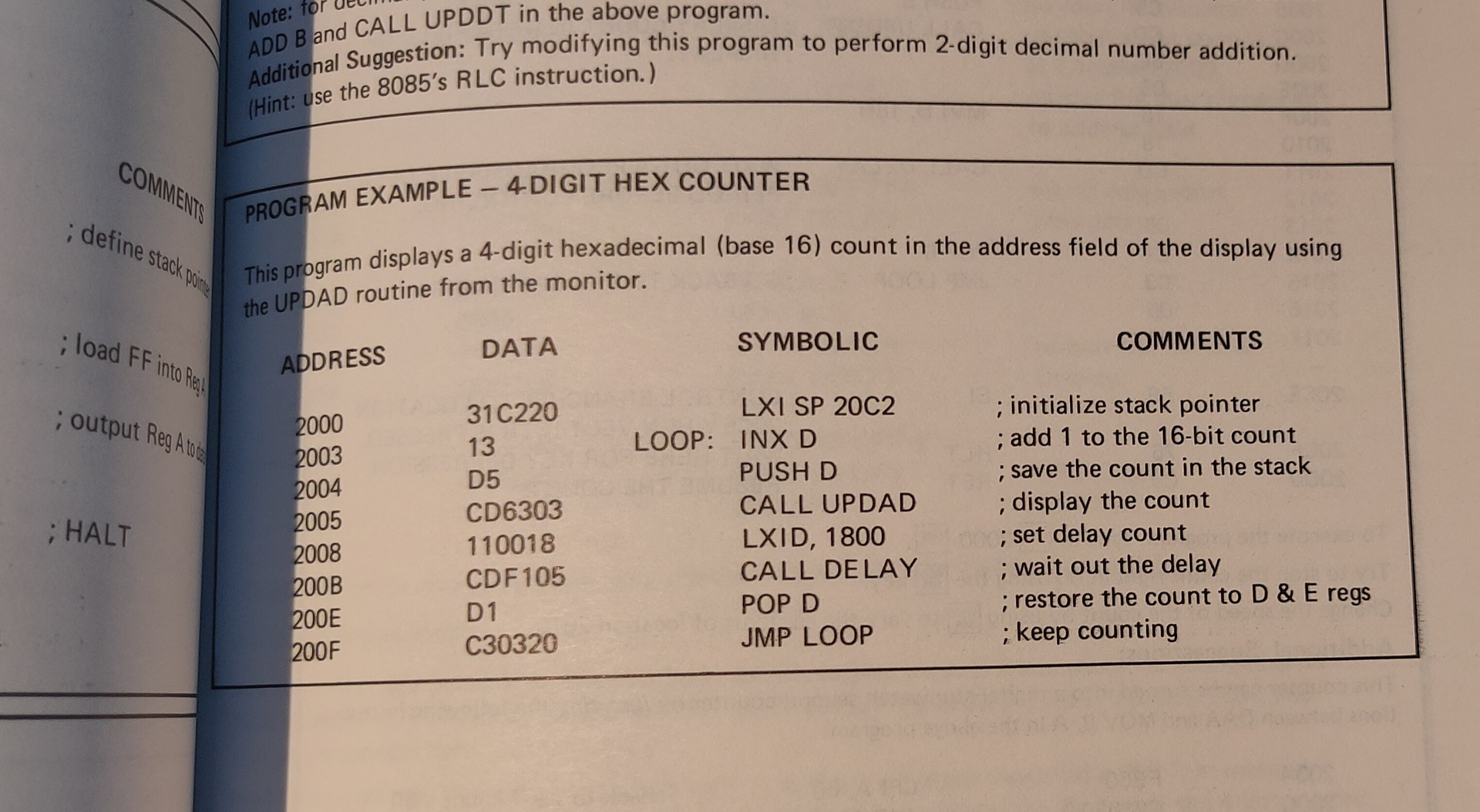
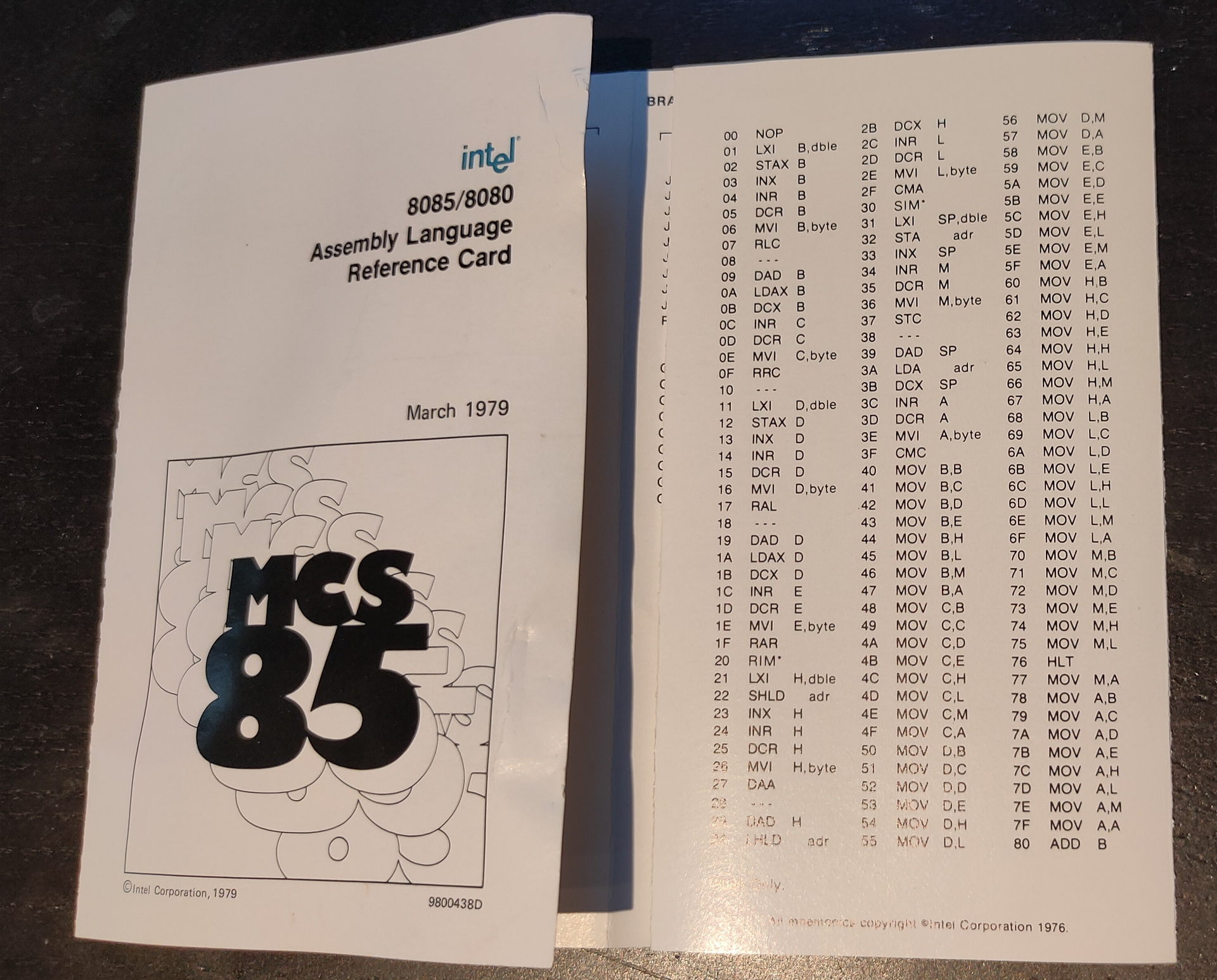
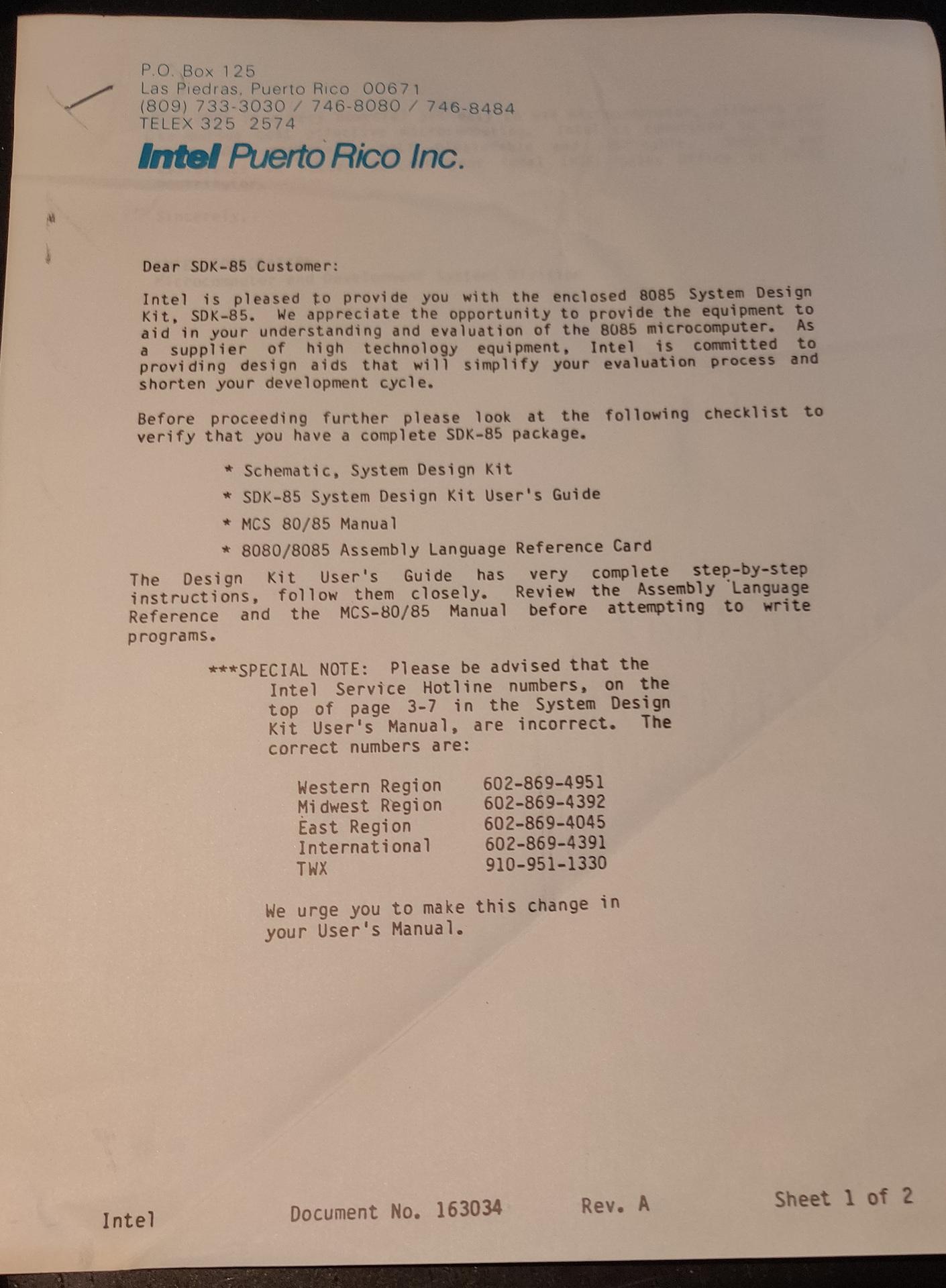
Found these old .. old mini-cassettes .. wish i could read these now. The sdk units we had, had tapedrives and few other hardware devices you could play with. Like a motor you could control, which had a disc with slots in it on top. These slots could be read and counted with a sensor to determine the speed.
Also this scanned pages, from school i found. There should also be a little notbook with programs and notes ..
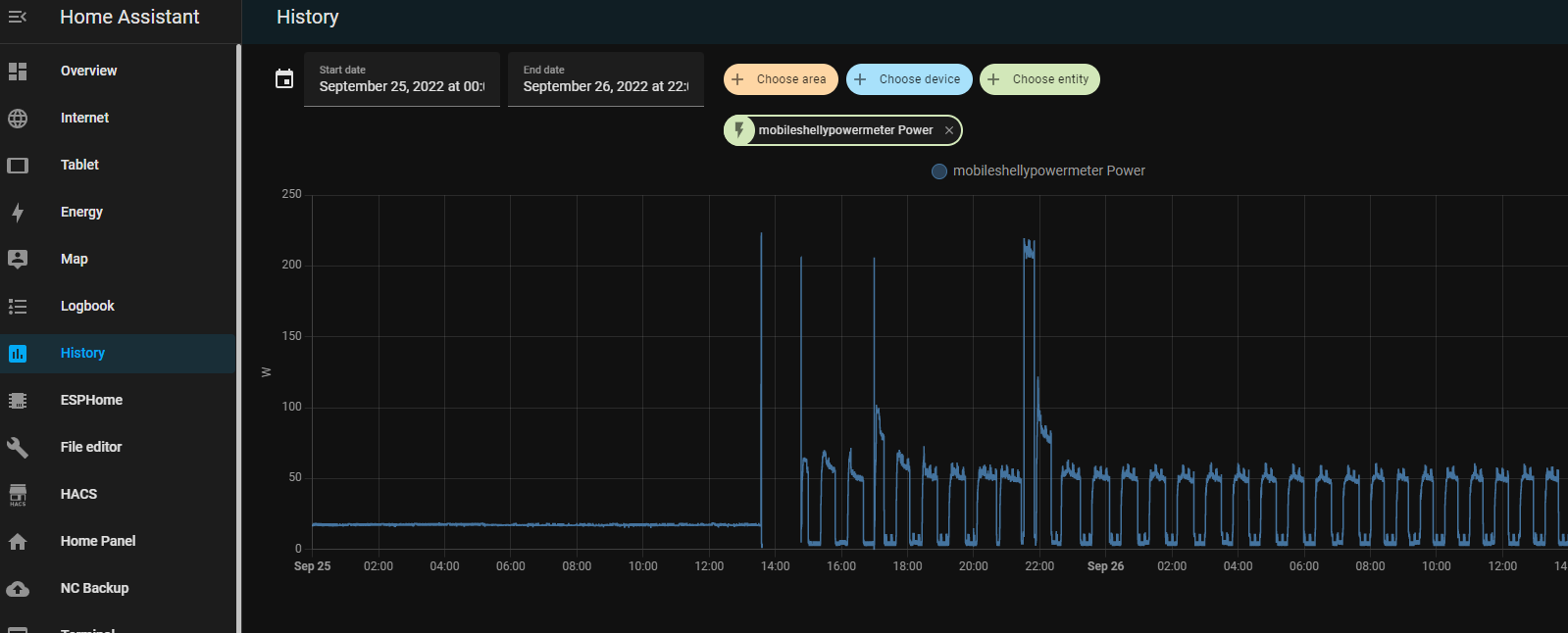
Having a lot of devices and running a Lab wil use a lot of energy. Now with the energy crisis in Europe, i had to take a closer look at whats using power in my house.
I notished some weird usage patterns while measuring.
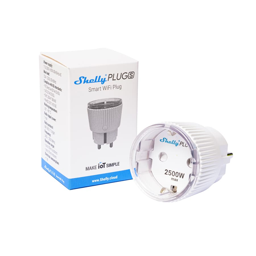
I’m using a few shelly power plugs, to measure devices and powerstrips.
With these devices you can control devices connected to it. On/Off/Timer etcetera. It wil measure the power usage in watts, and it even got a temperature sensor. I like the fact that it perfectly integrates into your home automation using an extensive API. curl commands to controll, and even MQTT messaging. Intergrating in Home Assistant is a breeze.
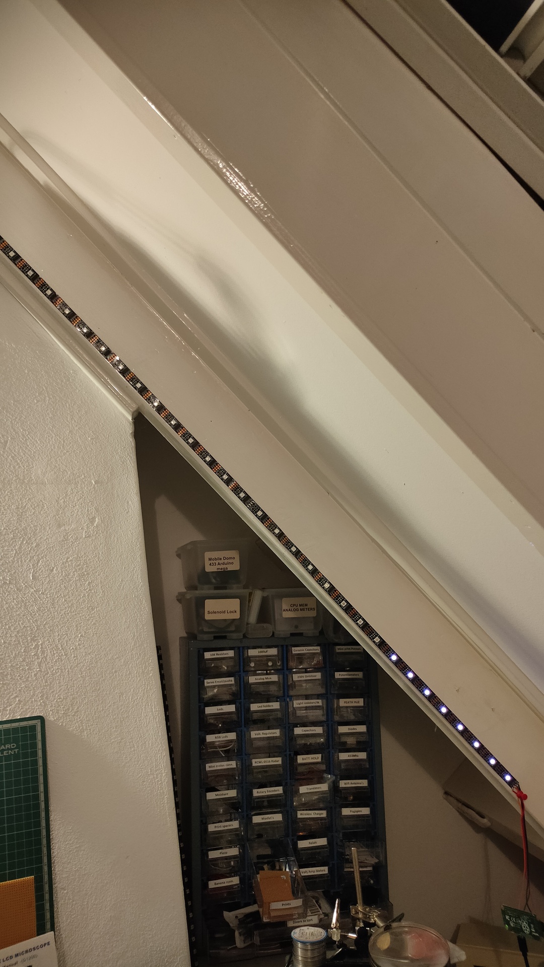
So i was monitoring a bunch of stuff using Nodered/Grafana/Homeassistant and saw some recurring usage. But being always late to check things, i made use of my ledserver i’ve build a long time ago.
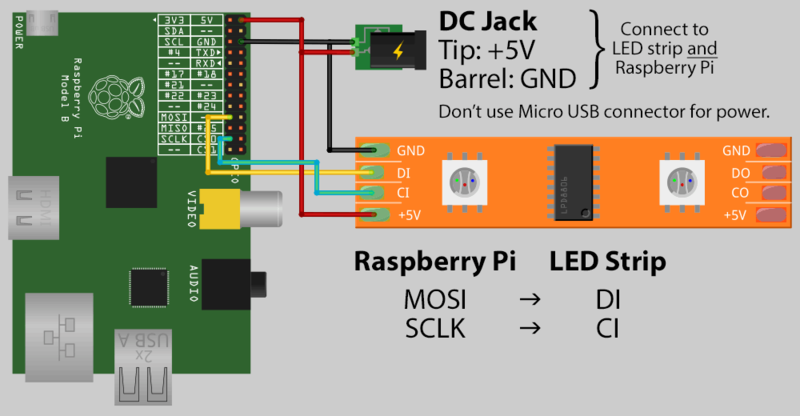
This ledserver consists of a Raspberry Pi Zero, with a led string and a API written in python.
Below is autostarted on the Raspberry
( I made this ledserver for work, it showed the status of servers and services. Beside that every colleage had a range which he could use for his own scripts. I made some little bash script templates to have led funtions standard in your bash profile.
#!/usr/bin/python


# apt-get install python-flask
#

import Adafruit_WS2801
import Adafruit_GPIO.SPI as SPI
import struct

from flask import Flask, render_template, request
app = Flask(__name__)

PIXEL_COUNT = 32
SPI_PORT   = 0
SPI_DEVICE = 0

pixels = Adafruit_WS2801.WS2801Pixels(PIXEL_COUNT, spi=SPI.SpiDev(SPI_PORT, SPI_DEVICE))

pixels.clear()
pixels.show()

@app.route("/led/<deviceName>/<color>")
def action(deviceName, color):
        if deviceName == 'reset':
                print ("reset")
                pixels.clear()
        print (deviceName)
        led = int(deviceName)
        s = color
        r = int(s[ :2], 16)
        b = int(s[2:4], 16)
        g = int(s[4: ], 16)

        pixels.set_pixel_rgb(led, r,g,b)
        pixels.show()

        templateData = {
                'rled'  : r,
                'bled'  : b,
                'gled'  : g,
                'deviceName'  : deviceName,
        }
        return render_template('index.html', **templateData)

@app.route("/control/<controlcommand>")
def actioncommand(controlcommand):
        if controlcommand == 'clear':

                print("clear")
                pixels.clear()
                pixels.show()

        templateData = {
                'controlcommand'  : controlcommand,
        }
        return render_template('index.html', **templateData)

@app.route("/range/<start>/<stop>/<color>")
def rangecommand(start,stop,color):
        s = color
        r = int(s[ :2], 16)
        b = int(s[2:4], 16)
        g = int(s[4: ], 16)
        startled = int(start)
        stopled = int(stop)
        while (startled < stopled):
          pixels.set_pixel_rgb(startled, r,g,b)
          startled=startled + 1
        pixels.show()

        templateData = {
                'rangecommand'  : rangecommand,
        }


        return render_template('index.html', **templateData)


if __name__ == "__main__":
   app.run(host='0.0.0.0', port=8080, debug=True)
Now you can control the leds with a simple curl command:
So today i made a little script to show power usage.
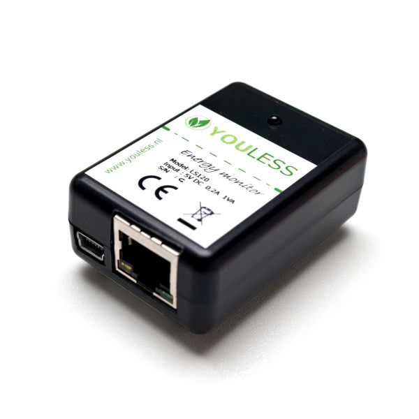
I’m reading the current power usage from a LS120 Youless
Youless LS120 device, which you can connect to your P1 connector.
With below bash script i’m reading the webinterface and update the ledstring. I was using this ledserver for general notification usage. Below a 2 minute hack ..
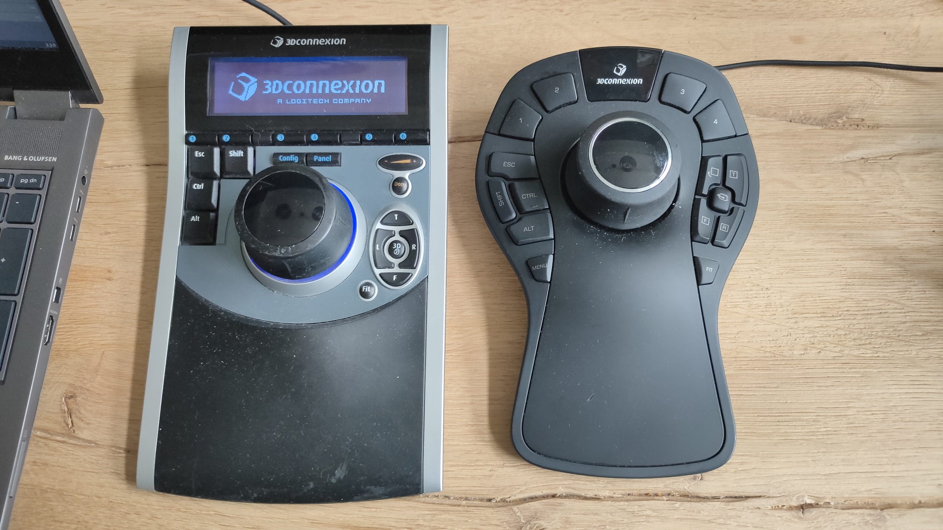
Yesterday i got two 3DConnexion 3D CAD mouses (mice) from my friend Vincent. While we where fixing his Mikrotik network i got to play with these cool devices.
I always wanted one of those, but they are quite expensive
First i tried to install the Software from 3DConnexion. It kindda worked but needed some workarounds and still wasn’t okay.
Downloaded 3dxware-linux-v1-8-0.x86_64.tar.gz (Maybe this version is TOO new, SpacePilot i a little ouder)
there is a install-3dxunix.sh, but it was made for Suse/Redhat

This program needed motif .. and a lot of libraries (libmotif/libxm)
After that some fonts xfonts-100dpi xfonts-75dpi


workaround was starting by
sudo /etc/3DxWare/daemon/3dxsvr -userName ${USER} -d usb
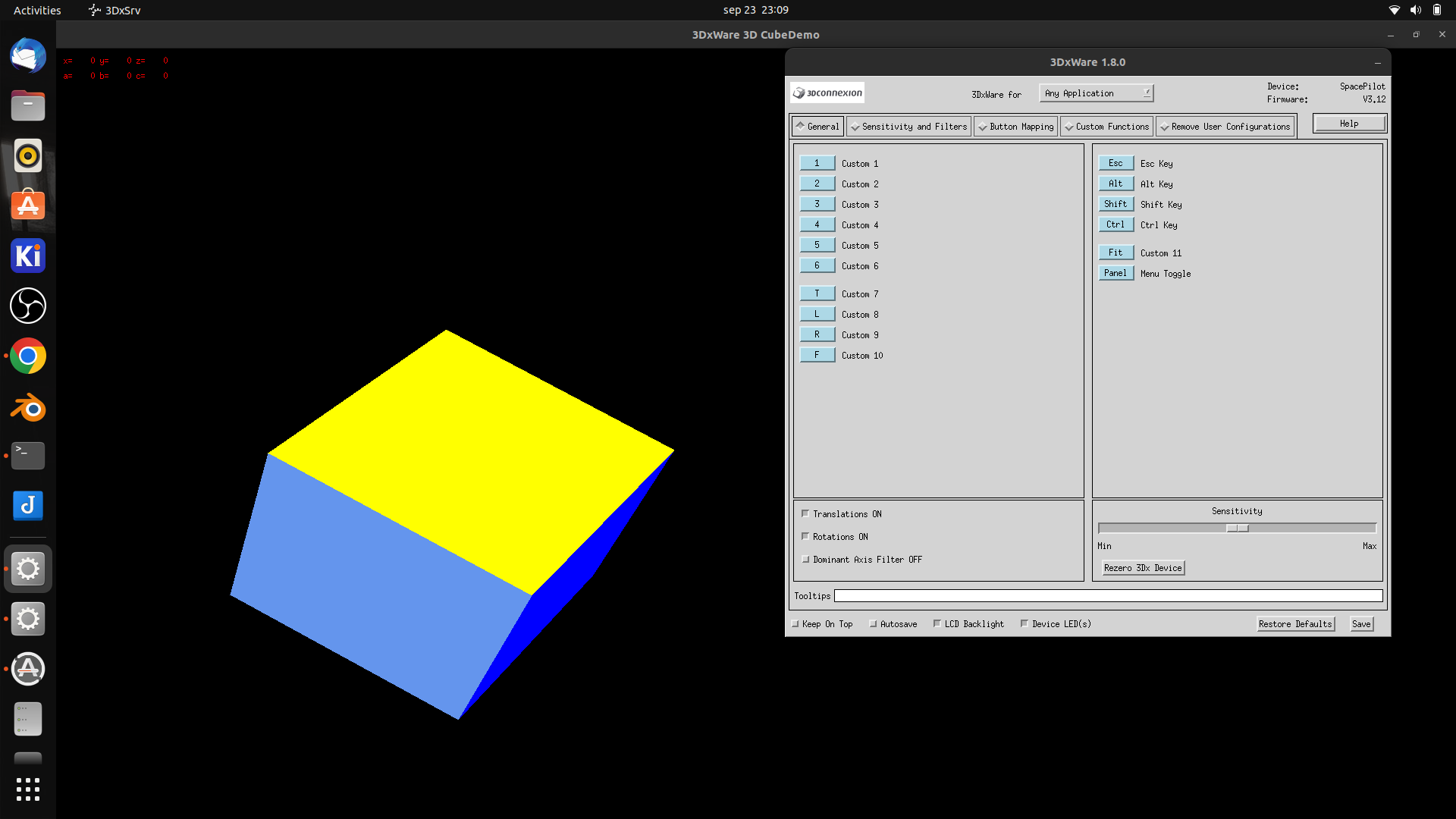
After that the demo program worked perfectly … but Blender didn’t After some tinkering it work a little, it was far to sensitive, and was all over the place.
Luckily i found a opensource replacement. https://spacenav.sourceforge.net/ git cloned the package, then i notished .. there is a precompiled version for ubuntu!
apt-get install spacenavd .. start the service .. and go!
i cloned the test demos (libspnav) and compiled those test programs.
apt-get install libglu1-mesa-dev
git clone https://github.com/FreeSpacenav/libspnav.git
cd libspnav
./configure
make
... fly is a nice little test program
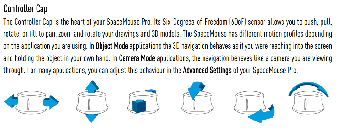
So lets start blender
Pan tilt roll .. nice!
This wil speedup modeling, and for sure sculpting !
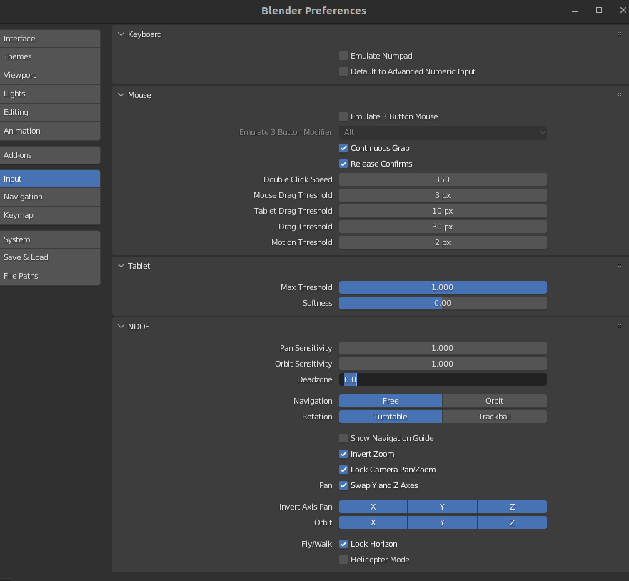
Some settings which worked for me .. let the tweaking begin!
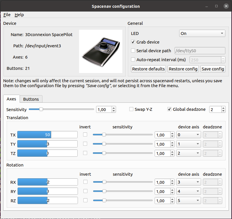
UPDATE: 2022-09-29
I removed the version in the apt repository, and installed everything from git. Now i have a cool configure tool
How about a quess the picture from our photo collection?? (123580 photos .. ) So i show a random picture, and when i press ESC it will show some information about the picture … Quess the year and the event
Well i gave myself 15 minutes to program something ..
I was watching a tv show meanwhile .. but i managed to come up with this …
This script is showing a picture, when you press ESC it wil show some details.After that it will select another random picture.
Improvements : reading tags and other metadata from my photo database, to give more information.