I was using zevv’s bucklespring way back since he was beta testing. https://github.com/zevv/bucklespring
Also cool-retro-term, i used whenever i felt nostalgic.
But both at the same time, how much fun is that!
(Both newly installed on my laptop, which i had to reinstall, because i f*cked it up beyond repair. installing openxr stuff. OpenXR is an open, royalty-free standard for access to virtual reality and augmented reality platforms and devices. )
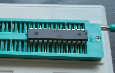
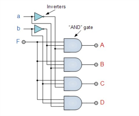
The ATF22V10 is a Programmable Logic Device. This means you can program the logic in the chip.
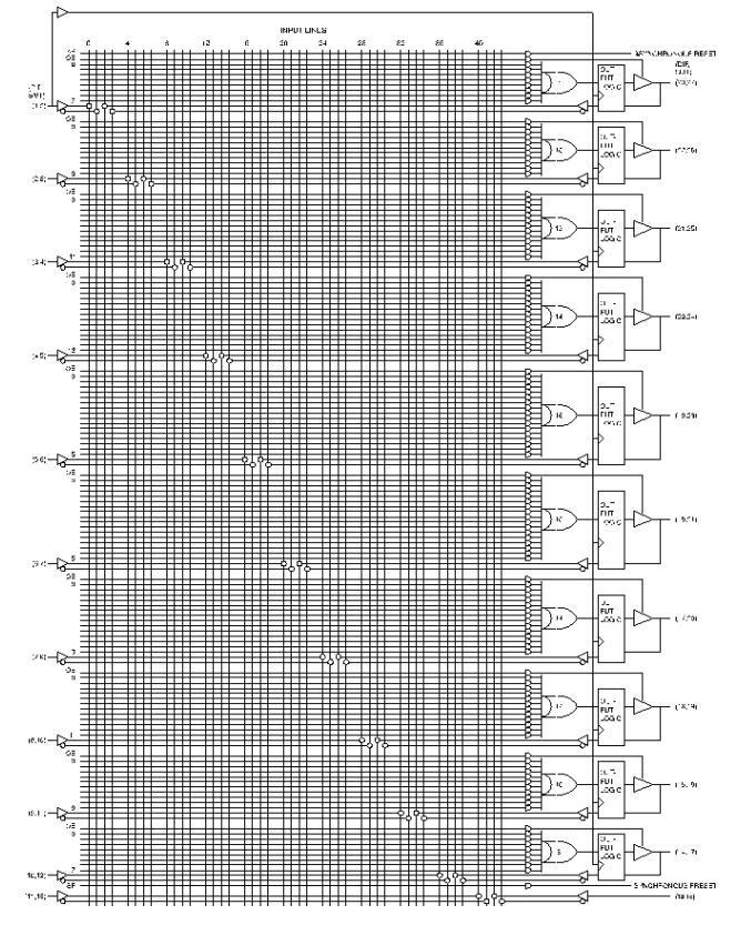
Internally it looks like a big matrix of connections which you can program to connect/disconnect from certain logic.
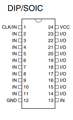
It has just a bunch of inputs/outputs
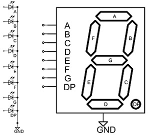
So if we want to have a 7 Segment decoder (you can easily buy a BCD decoder .. but these only work for displaying 0-9 and not 0-9A-F for displaying HEX numbers)
7 Segment display
Binary IN
7 Segment decoded
Displays
D C B A
A B C D E F G
0 0 0 0
1 1 1 1 1 1 0
0
0 0 0 1
0 1 1 0 0 0 0
1
0 0 1 0
1 1 0 1 1 0 1
2
0 0 1 1
1 1 1 1 0 0 1
3
0 1 0 0
0 1 1 0 0 1 1
4
0 1 0 1
1 0 1 1 0 1 1
5
0 1 1 0
1 0 1 1 1 1 1
6
0 1 1 1
1 1 1 0 0 0 0
7
1 0 0 0
1 1 1 1 1 1 1
8
1 0 0 1
1 1 1 1 0 1 1
9
1 0 1 0
1 1 1 0 1 1 1
A
1 0 1 1
0 0 1 1 1 1 1
B
1 1 0 0
1 0 0 1 1 1 0
C
1 1 0 1
0 1 1 1 1 0 1
D
1 1 1 0
1 0 0 1 1 1 1
E
1 1 1 1
1 0 0 0 1 1 1
F
Now we see that segment A is 1 in the case of (0,2,3,5,6,7,8,9,A,C,E,F)
When programming the PLD we can write that as: (note / means inverted a plus is OR, and * is AND) So A is 0 in case of input being (1,4,B,D)
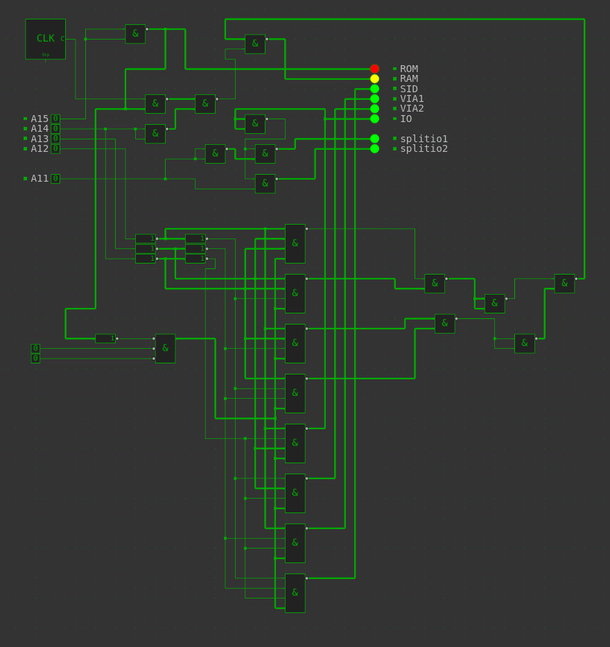
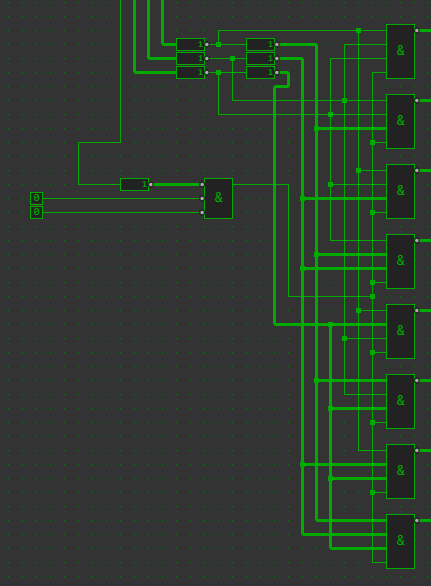
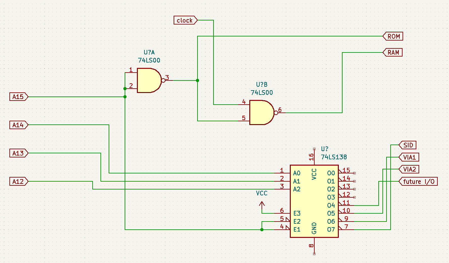
Made a simulation of my new address decoder. It uses a 74LS138 and a bunch of NAND gates. You can safe using 4 NAND gates if you are not going to use split IO
Address
8000-FFFF
ROM
ROM
7000-7FFF
Sound chip
SID
6000-6FFF
Display + cursor
VIA1
5000-5FFF
Keymatrix
VIA2
4800-4FFF
split io
IO
4000-47FF
split io
IO – ACIA
0000-3FFF
Uses clock
RAM
Above part is a single chip 74LS138
UPDATE: Found some 74LS139, so i could have changed some things around.
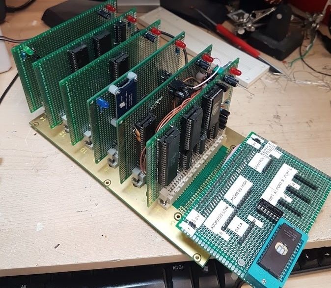
I found some stuff while sorting out some old computer stuff. Way back, when my Amiga was my main computer, i wanted to make my own version. A modular one.
So i started to segmentize the amiga, to put it on several exchangeable cards.
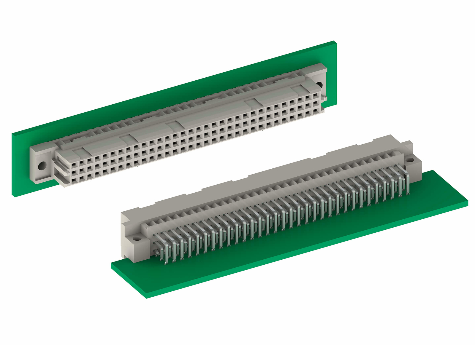
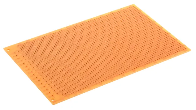
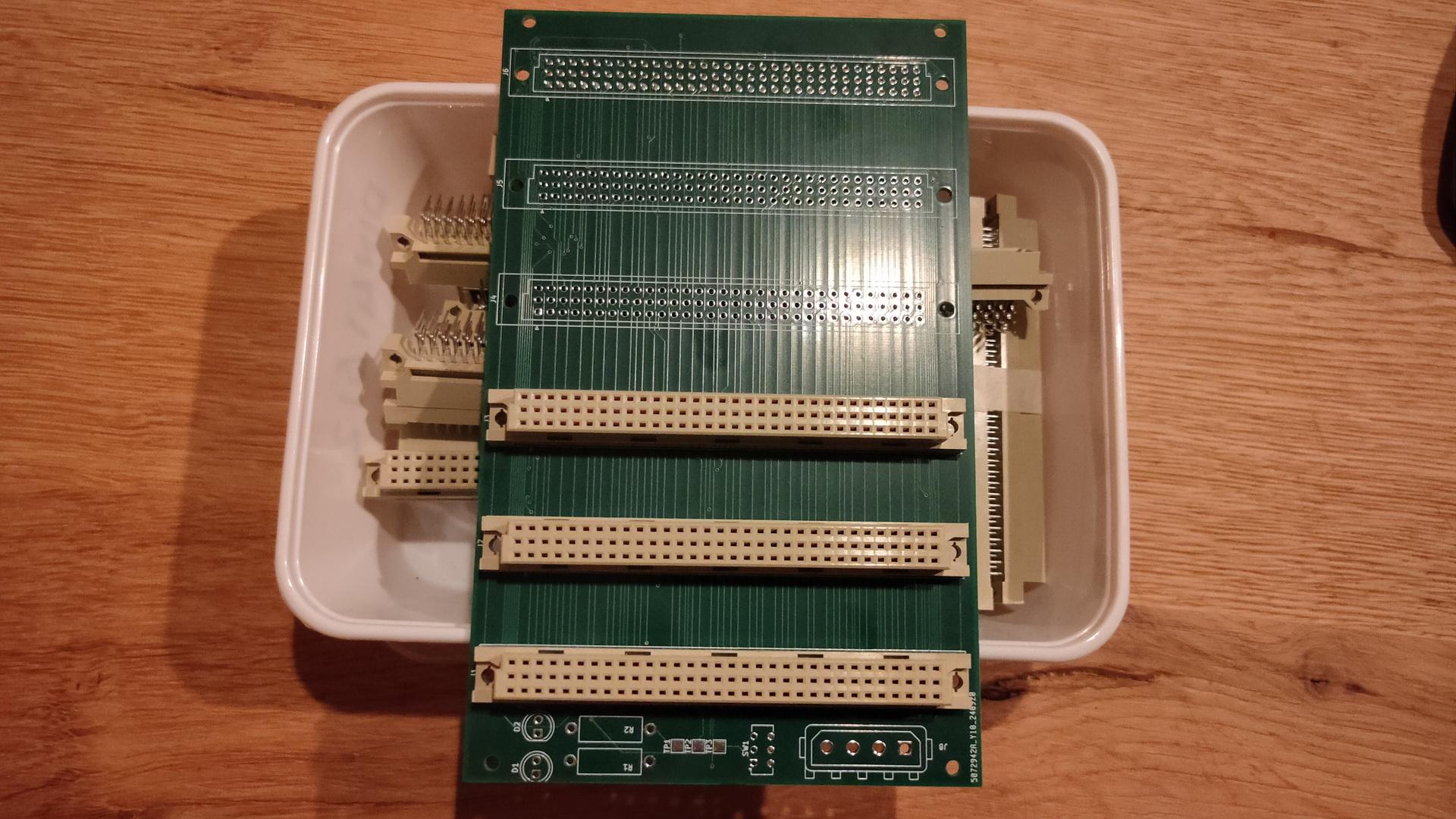
Eurocards are standardized prints 150mm x 100mm, mostly with a DIN41612 connector.
DIN41612
Eurocard example
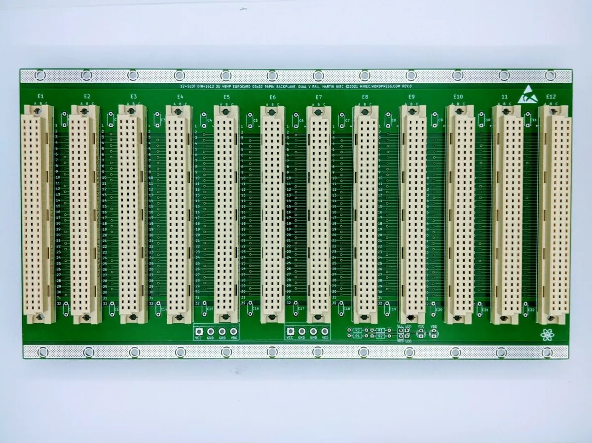
When you make modules you can change/upgrade/test, you can have a very easy interchangeable system using a backplane like this
So i started planning those modules:
CPU – 68000 but upgradeable to 68030 or alike
Memory – With expansion
Sound
Video
More IO possibilities
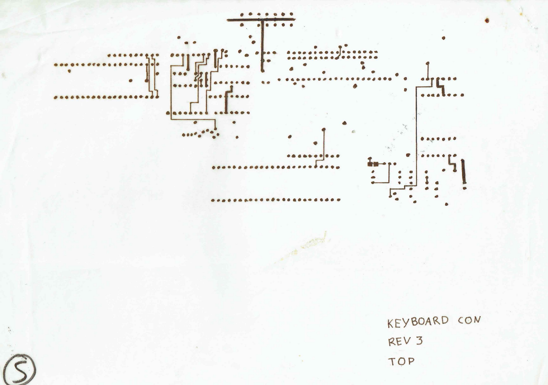
Keyboard (see more at the bottom of this page)
I had a nice case which could hold a big backplane, custom powersupply. And a front panel containing drives, leds and knobs. (I know i have more info on this somewhere on my fileserver)
A nice example picture i found on danceswithferrets website
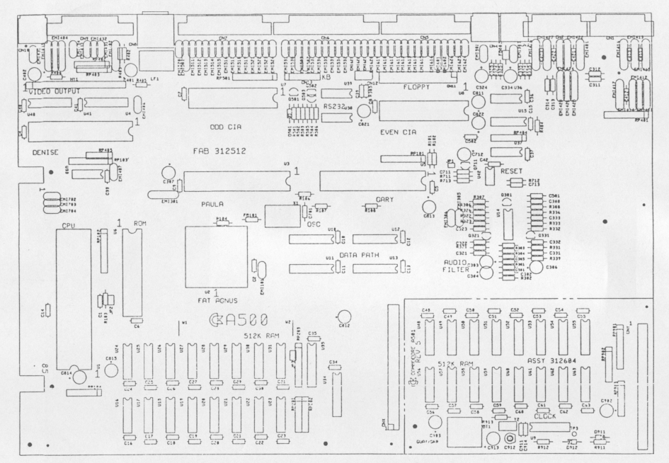
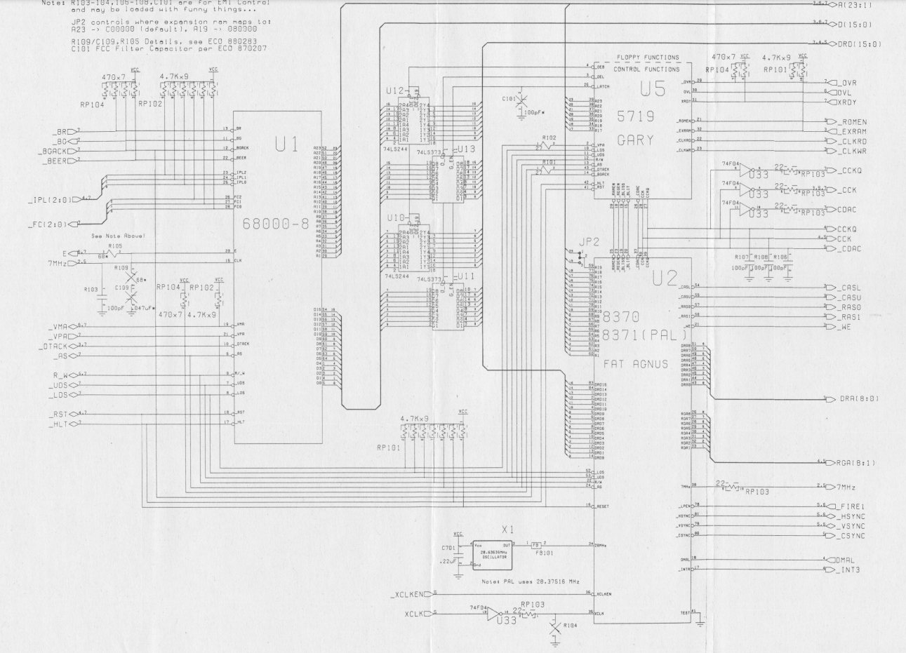
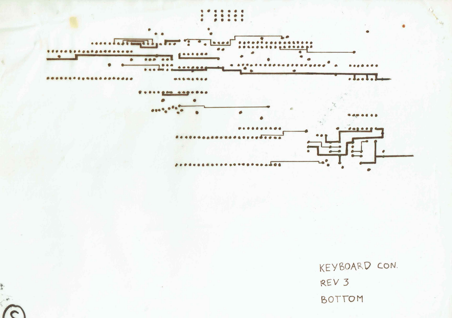
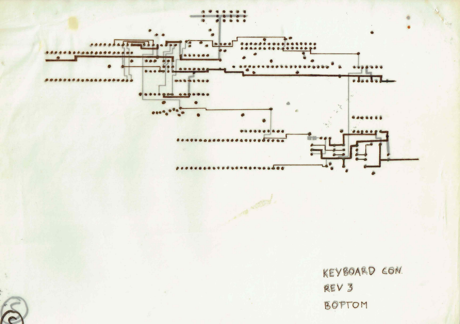
I never finished this project. I used Tech Manuals and print layouts to understand how things where done.
Part of schematic
I started to draw the modules like they where placed on the print on semi transparent (chalk)paper, the kind of paper that was used for electronic and mechanic diagrams.
TOP Part of printBottom part of printBoth on top of eachother
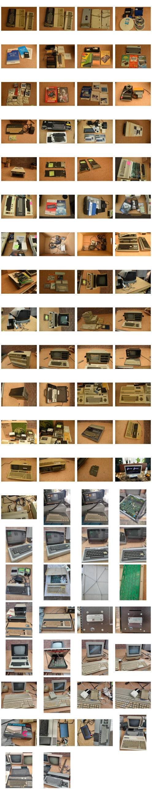
The last days i’ve been selling a lot of my old computers. They have been in my collection for many years, but now its time to part. Time for others to enjoy them.
(Instead of posting which ones are being sold and which i’ve still got on this page i’ll make another post)
I started collecting when i studied computer sciences. It’s a wonder my parents attic wasn’t collapsing. (They let me store many computers on their attic, let me run a mainframe in the house (previous post) and let me have computer-parties (pre-lan) in their home. (They even left, and gave me the space) .. 15+ teens with computers … there was a pingpong table in the livingroom (besides the other tables in the house ) For all computers.
Then i’ve got even more, when living on my own. (At some point about 140. )
A few years later i got rid of uninteresting computers (to my taste at that time) and incomplete ones. Then i filtered-out the non working.
Still leaving with a lot of computers, i kept these for many years.
Now i only want the ones i’ve worked with, or are special to me.
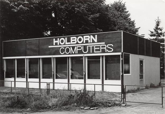
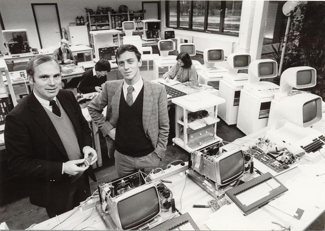
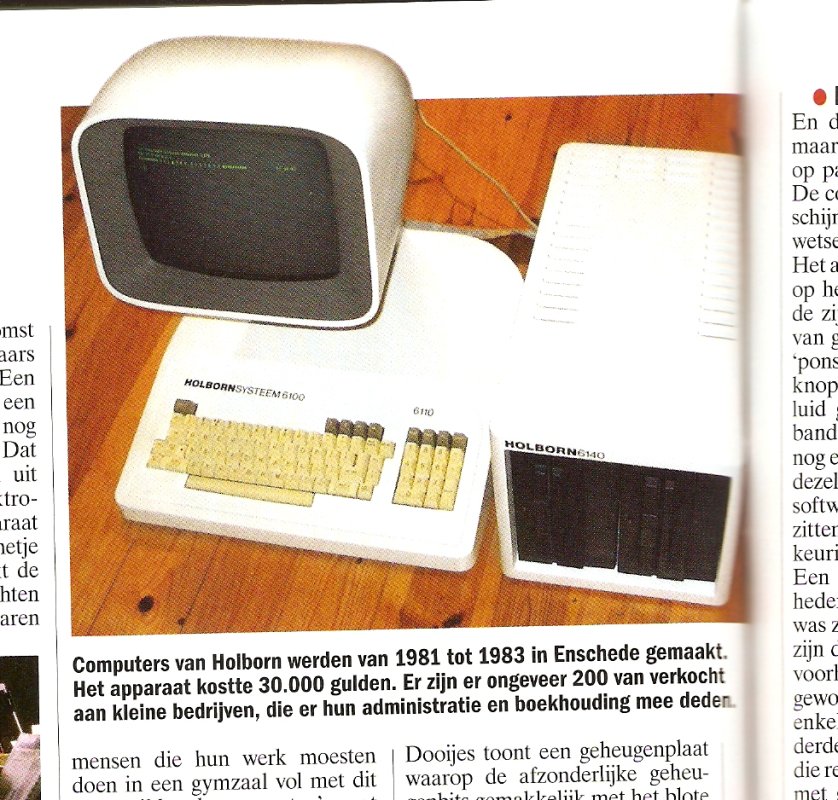
My first computer was a Commodore Vic-20. Friends had the popular C64. So i kept 2 of both. In Junior Technical School i’ve used the BBC Acorn a lot (Funny story below) My then friend Richard had a Atari ST, loads of fun we had with that machine, so i’m keeping a Atari 1040STf. Another friend used a Apple SE, so that one i also keep for now. I’ve been programming a lot on 80×86, the first dos PC’s, i’m still looking for a old machine (Laser XT) which i used way back then. But for now i’ve got a Sinclair PC200. I’ll keep a old Commodore PET 2001, because its cute. Besides having a cute PET, i’ve got a Holborn System. Made in Holland (Enschede), there are only a few left according to some sites: only 200 made! (Holborn means Holland Born) One of the inventors was from Holten, my birthplace. (Polak)
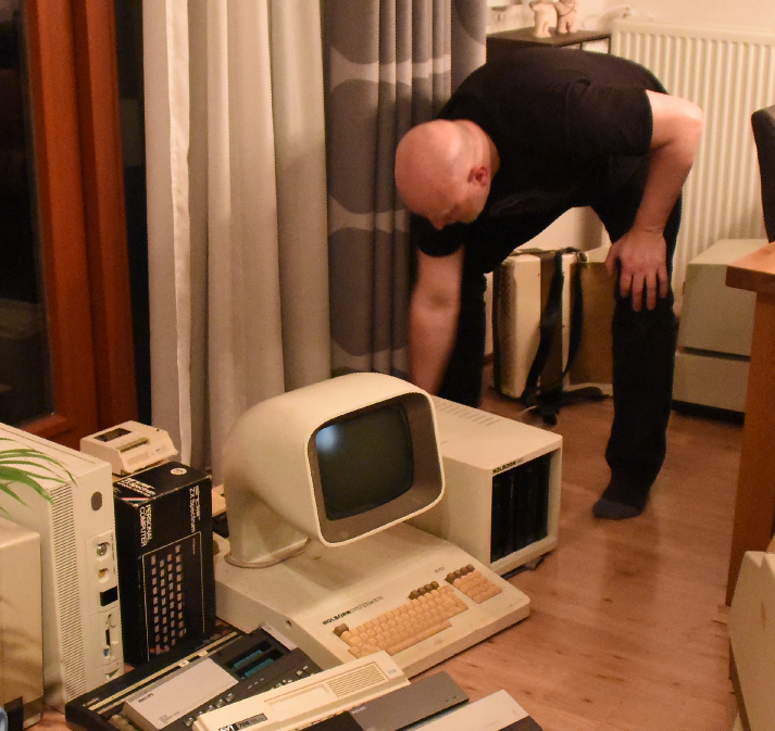
Putting the system together in 2018
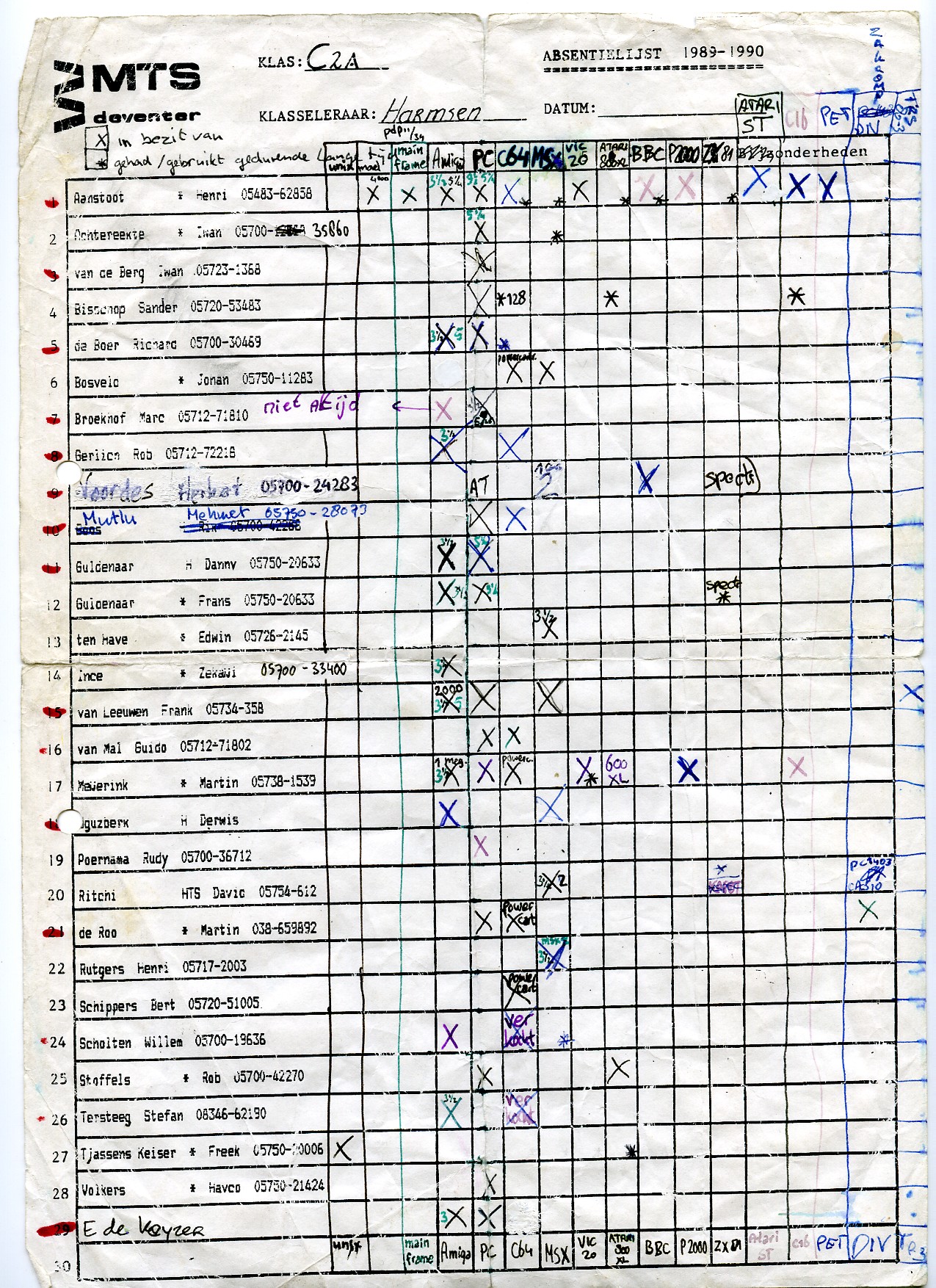
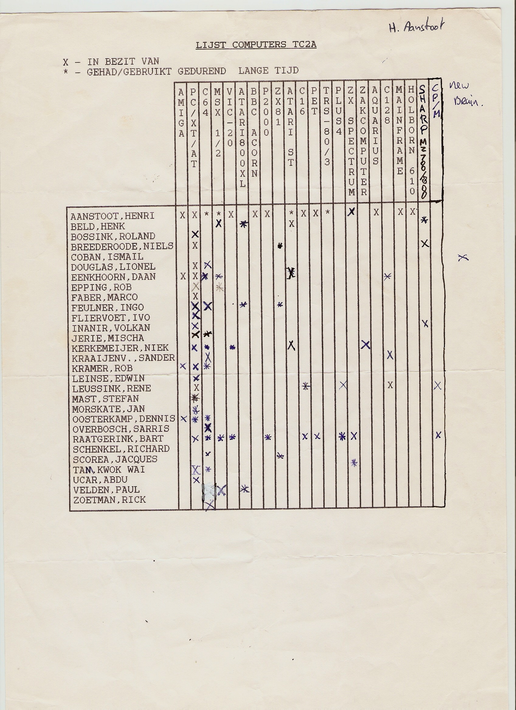
At school we kept a list of everyone’s collection.
Soo .. the story about the BBC Acorn.
When i was at school outside study hours, i went to the computer lab. This was one classroom with about 16 BBC Acorns and a master (teacher station). When they saw how enthusiastic i was, i got the key to the classroom. I even got access to the master system. And after a little hacking i’ve gained access to the teachers files. There was a simple network system, i think it was called Econet. The teachers system was the only one with a disk station.
I liked the ‘highres’ line graphics you could make on the machines. (640×256) So i’ve wrote a lot of programs using this mode. I even wrote a program which drew a 3D robotarm on screen using wireframe graphics. At that time my mathematics scores where .. bad. Wasn’t interested i think. But drawing 3D robotic arms are not possible using mathematics, like using sinus, triangulary etcetera. So when my mathematics teacher saw my program, he didn’t believe me. So .. fooling around in the computer lab, i missed start of classes. And later on .. worse .. i almost was not allowed to do my final exams. I was late several times (and one of the first to leave, …. straight from and to the computer lab. )
I’ve got some programs printed on paper, i will use my leftover BBC Acorn (or a emulator) to capture some screen examples.
Sold stuff
UPDATE : Selling a lot, but i’ve bought some others between 2020-2023
SDK-85
Laser Xt/3
80386 DX
Also a “new” 1084 monitor (CRT for a Commodore 64) Now i have to look for a VGA Crt to get old vga-register manipulation programs working.
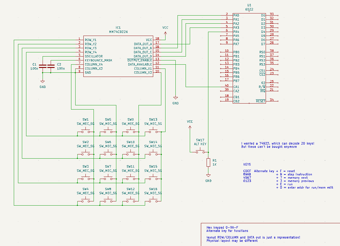
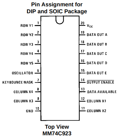
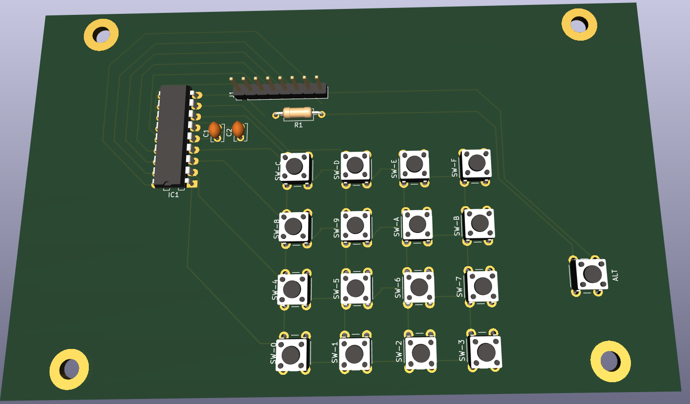
Above is my design for a hex keyboard to enter opcodes in hex using a simple monitor program. i used a 74ls922 which can decode a 4×4 matrix. I’d rather had a 74ls723 which can encode 20 keys.
Nowhere to be found. So i have to think of a new plan.
Now it is configured as follows:
C
D
E
F
8
9
A
B
4
5
6
7
0
1
2
3
When pressing the alternate key
addr (to implement)
run (1/2 implemented)
reset (to implement)
step instruction (to implement)
memory next
memory previous
PCB design for matrix hexboard with place for notes
Meanwhile i’ve ordered new keys (the ones i’ve been using for my photomanager project and wnat to have a setup like this:
?
?
addr
run
reset
C
D
E
F
?
8
9
A
B
step
4
5
6
7
mem next
0
1
2
3
mem prev
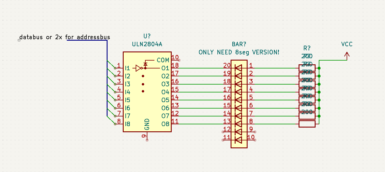
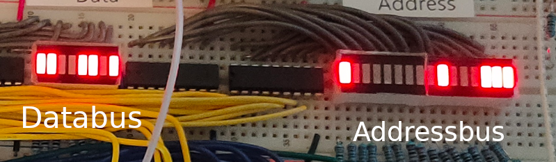
When you want to show the status of busses and alike, you can’t use a led and restistor directly on the bus, it will require too much current. So i’ve been using below schematic which uses a darlington array.
Now i can display databus, address bus and i’ve been using this for address decoding logic and hex keyboard.
I’ve implemented a second VIA chip, and ordered components to amplify the SID sound part
I’ve used a lot of programming languages, and besides that a few scripting languages.
Scripting is used to automate stuff, but probably use other tools under the hood. A programming language can probably do this by itself. Most of the time a programming language needs compiling into a executable form. Whereas a script is directly intepreted at runtime.
I’m not good at programming, but i understand the syntax and can read most of it. My programming is mostly by example/copy-paste. Below a list of programming languages and a table below that some scripting languages.
Sooo .. what do i like, still use and why?
Bash is my swiss army knife. Making Web stuff? – PHP Iot – C and Javascript Advanced programming/Longer programs or Machine Learning – Python
And because of recent projects … i have to mention 6502 machinecode!
Programming languages i’ve used
Basic
The first programming language i learned. There are many dialects for many different systems.
Pascal
I learned to program in school. Generic pascal and later Turbo Pascal
PLM/86
This is relatively unknown programming language. Written for intel processors. It used a lot of ms-dos subroutines. Like dsso which stands for dos-standard-string-out. dsso(@(‘Print this text’,eos)); And called a dos routine like below (assembly example) mov dx,(messageaddress) mov ah,09h int 21h
Assembly
Started with 6502 assemby on my little home computer (a vic-20). After that i learned to program 8085 assembly in school. Also learned a little Z80 programming. When i got a amiga i started with 68000 assembly. And getting the hang of it, some friends and me started programming 80×86.
C
For a project I needed C programming to control a parallel port, for example for my controllable webcam. Also recently the microcontrollers like the Arduino’s are programmed in C/C++
Perl
Perl was also a interesting language, i bought myself a book and started with the examples. One of my friends was a Perl wizard, but i could never get the hang of it. Even with his help.
Tcl/TK
TCL stands for Tool Command Language, i used the TK extension. So Tcl/TK i used for creating GUI tools in linux. But like what i later used zenity and yad, i think these are more scripting languages.
PHP
PHP i used extensively, one of my first big projects was a tunesearch engine with a mysql database.
Python
The last years i’ve been using python more and more. Python has become the de facto standard for IT.
Haskell
Well .. it is a programming language but i only use it to configure my Xmonad desktop.
Javascript
I’ve made a lot of webbased nonsence. PHP/CGI scripts/flash but i also used javascript. Now i’m primarily using javascript for NodeRed
Scripting languages i’ve used
bat
Dos batch files is a kind of scripting language
Ksh
Korn Shell, i did a workshop ksh because i was a AIX admin. Didn’t use this much, because you could install the linux toolkit, and could use bash after that.
Bash
I write a lot of things in bash, this is my preferred tool for fast and easy automation. When it’s web based i use PHP
Lua
I had to write some plugins for my Flightsim Setup
What about Sql, Dbase, Sed, Puredata and blocky those are all on the Programming Lanuages page of Wikipedia??? Well those i find more of a application markup language. Then you can say abc-music and bmw (bagpipe music writer) are languages also!??
Some call Ansible a programming language, but this is incorrect. It is driven by python scripts and yaml config files.
Below some code part examples of different CPU assembly code
#6502
    PUSH CX
    PUSH DI
    PUSH SI
    MOV AX,cry
    MOV BX,(2*40)
    MUL BX
    MOV DI,AX
    ADD DI,(2*31)
    MOV SI,adr1
    SUB SI,8
    MOV CX,8

Z80
    LD H,00H
    LD B,01H
    LD A,(IX+00)
    OUT (01H),A
    LD A,(IY+00)
    OUT (02H),A
    DJNZ LUS3
    LD B,01H
    LD A,(IX+07)
    OUT (01H),A
    LD A,(IY+07)
    OUT (02H),A

#8085
    LDA 2050
    MOV H, A
    LDA 2051
    ADD H
    MOV L, A
    MVI A 00
    ADC A
    MOV H, A
    SHLD 3050
    HLT

#68000
    bsr send
    bsr delay2
    move.w #$38,d0
    bsr send
    bsr delay2
    move.w #$38,d0
    bsr send
    bsr delay2
    move.w #$01,d0
    bsr send
    bsr delay2
    move.w #$0c,d0
    bsr send
    move.w #$06,d0
    bsr send
    rts

#80x68
    mov bx,split
    and bx,1111111111b
    mov dx,3d4h
    mov al,18h
    mov ah,bl
    out dx,ax
    mov bl,bh
    xor bh,bh
    shl bx,1
    mov bx,[bx+offset ormsk]
    mov al,9
    out dx,al
    inc dx
    in al,dx
    and al,10111111b
For assembly i use or used below: vasm – vasm is a portable and retargetable assembler – which can be used for a lot of different CPUs masm – a assembler for 80×86, i used this for programming on DOS machines. Also for little projects i used the alway available debug executable. seka/masterseka – programming 68000 on my amiga
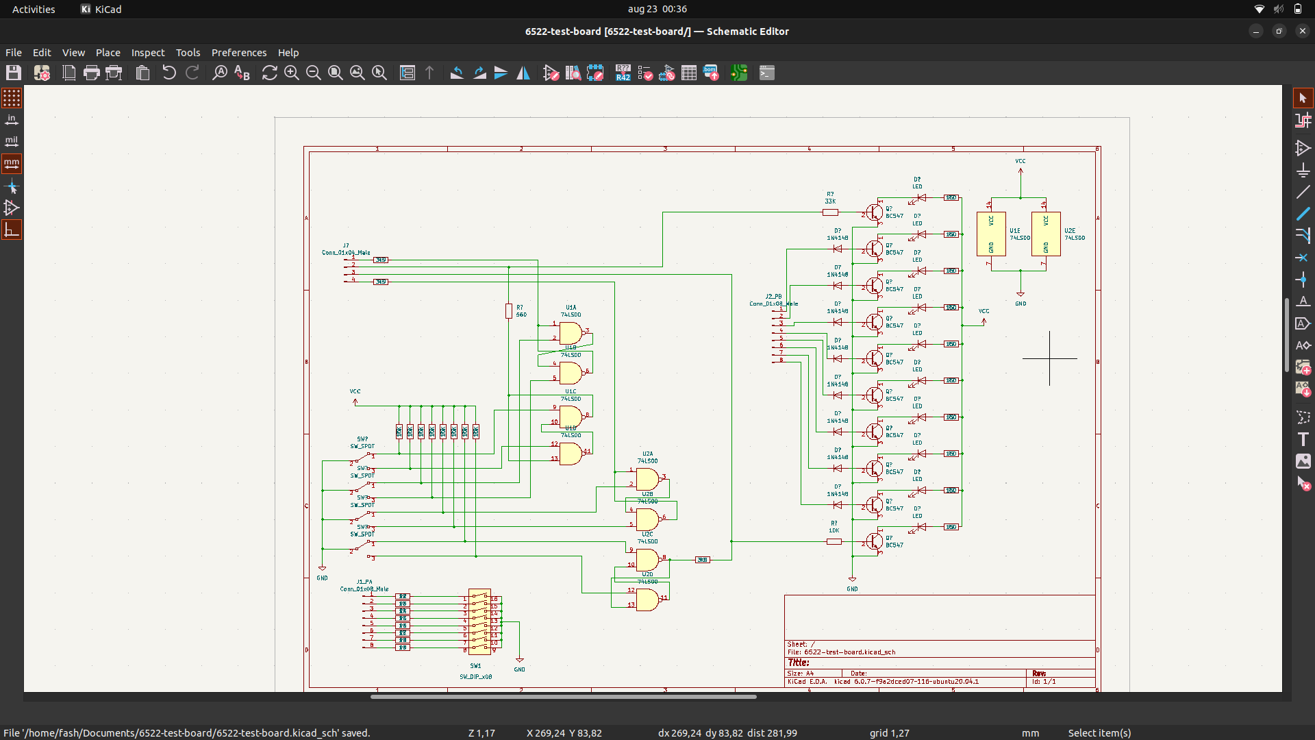
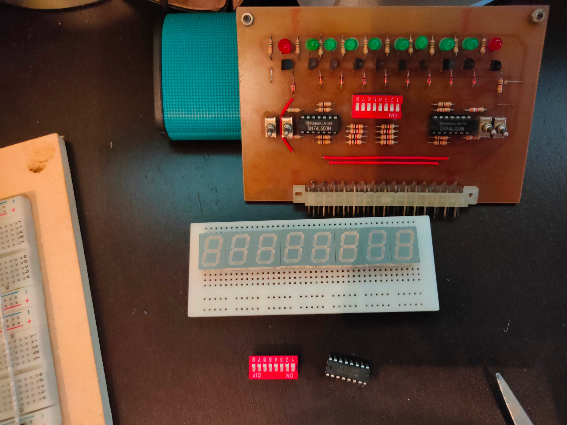
Above is my Kicad design (reverse engineering print below, which was made for my 6802CPU, which i could use to test the 6822 PIA) The 6822 is simular to 6502 in design. So i’m going to redo this for my 6502. The 7 segment displays are a start of hex-keyboard/display combo i’m going to post more of in the next days.
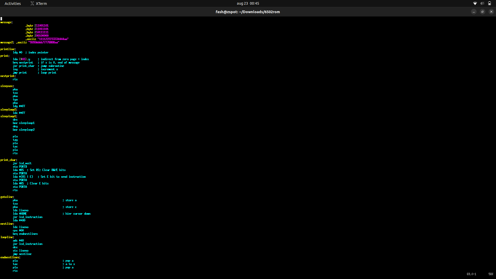
Below a part of the rom for the LCD dual line display.
Part of the ROM assembly code, top part is text (o.a. japanese)
Started to write routines which i can call to manipulate the display. Setting the pointer to a message, setting the line to use and a subset of controlls like: Center, Right, binary to ascii, scrolling, etcetera
        lda #0             ; set line number
        sta lineno         ; store
        jsr gotoline       ; goto line in display
        lda #<message      ; get address from message and store for printline subroutine
        sta messagestore
        lda #>message
        sta messagestore+1
        jsr printline      ; print

        lda #1  ; set line number
        sta lineno      ; store
        jsr gotoline
        lda #<message2
        sta messagestore
        lda #>message2
        sta messagestore+1
        jsr printline
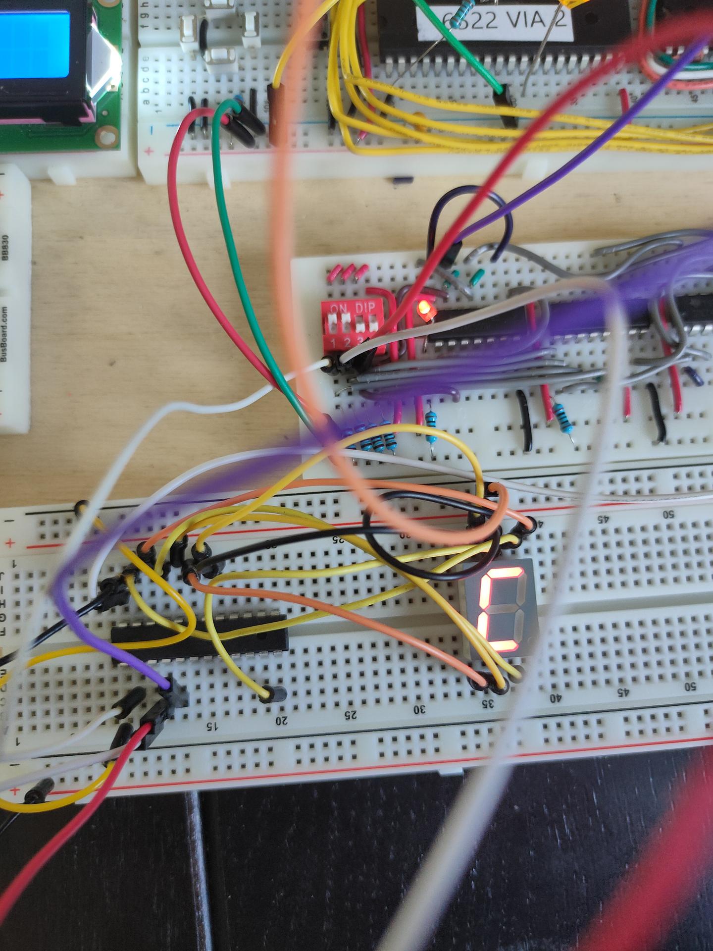
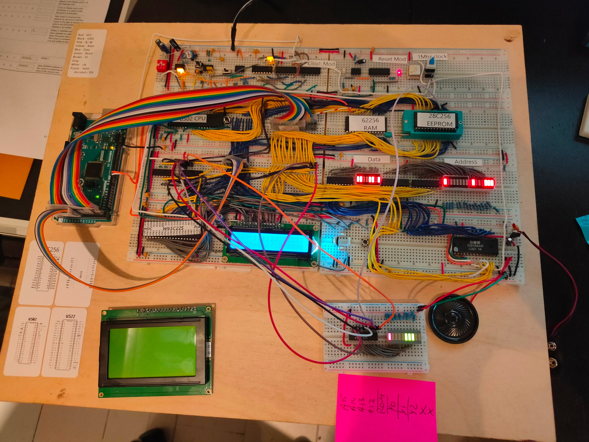
Above additions: New address decoder Below left the new graphical display, below right a test board which shows address lines and decoded chip-enable lines.
A15 high -> ROM A15 && A14 low -> RAM combination of A15 low and A14 high – A13 and A12 wil select peripherals.
Adress decoding
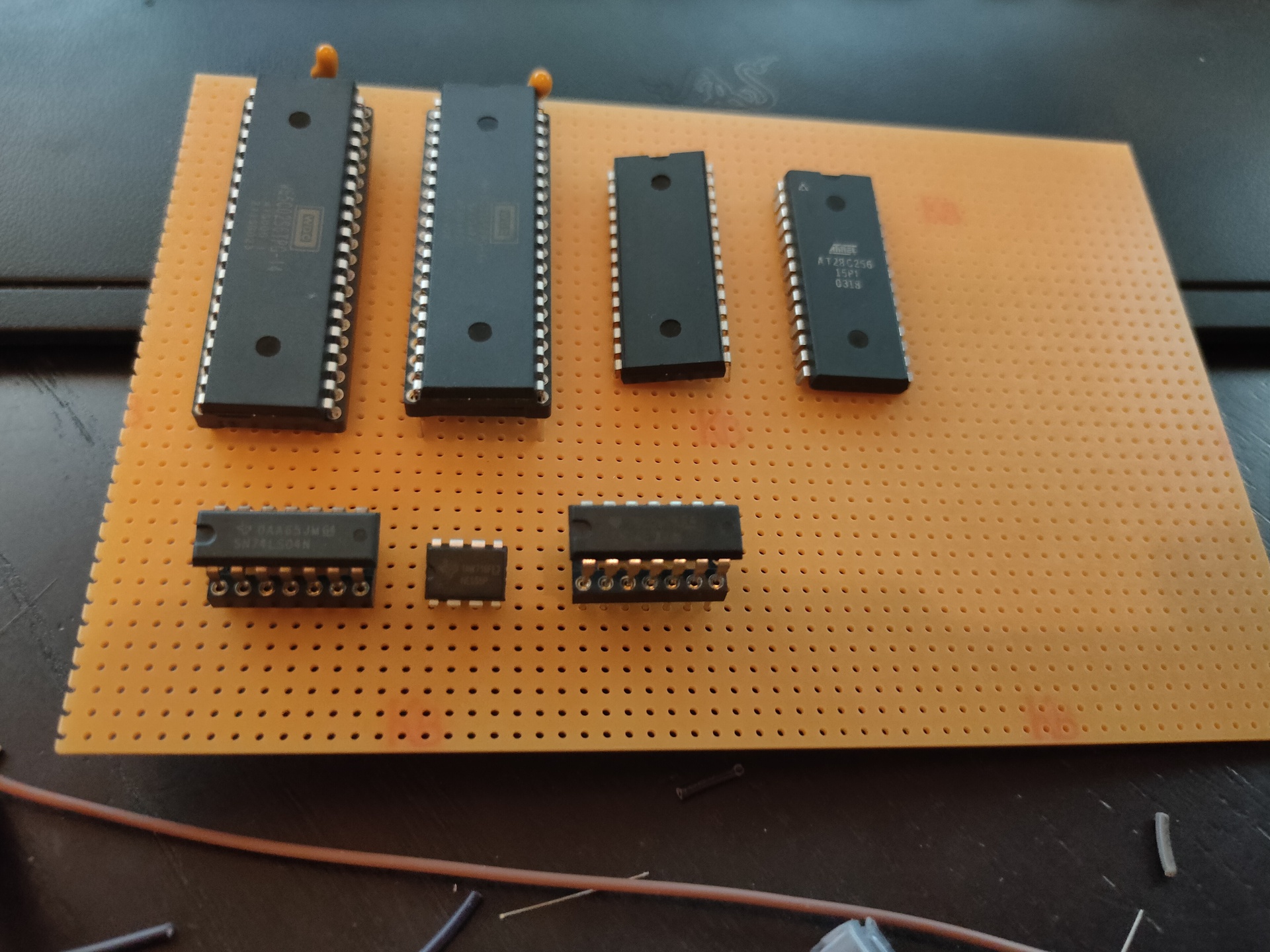
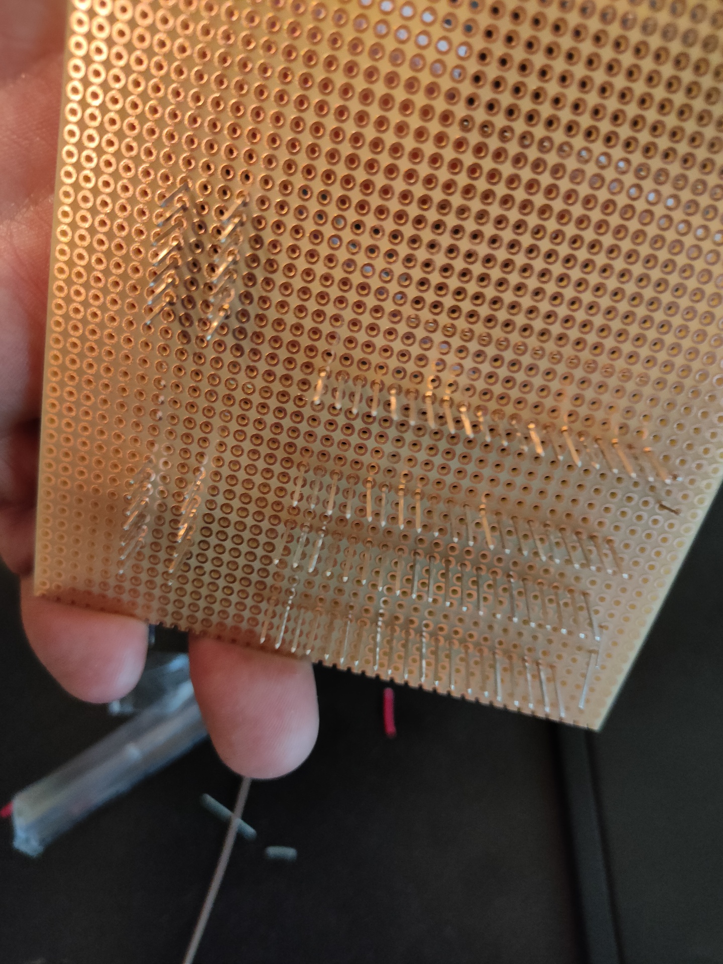
Start of a wirewrapped version
Above is a start of a wirewrapped version, i also started a PCB design in KIcad that will continuously be changed as i alter designs.
UPDATE SID Working! Using new address decoder.
SID = $7000

makesound:
	lda #0
	sta SID+$5 ; Channel1 - attack/decay

	lda #250
	sta SID+$6 ; Channel1 - Sustain/Release

	lda #$95
	sta SID+$0 ; Channel1 - Frequency low-byte

	lda #$44
	sta SID+$1 ; Channel1 - Frequency high-byte

	lda #%00100001
	sta SID+$4 ; SAW + Gate

	lda #$0f
	sta SID+$18 ; Volume max