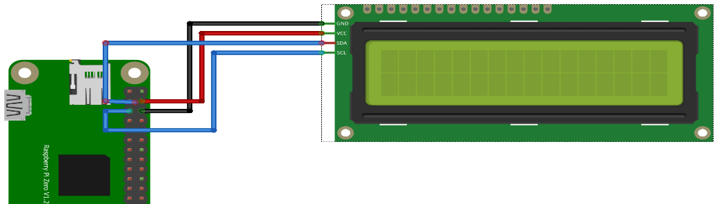
I’ve installed a headless Raspbian on a Pi Zero with a 2×16 Chars lcd display. As part of the Escape Room over the internet
Using the raspberry imager: I’ve set the username/password and ssh access in this tool. For wifi access i’ve placed below file on the SDcard in /boot (You can do this in the tool, but i want to make this dynamic when connected at a remote site.) file: wpa_supplicant.conf
sudo raspi-config
Interface options and enable I2C

sudo apt-get install python3-smbus

wget https://gist.githubusercontent.com/DenisFromHR/cc863375a6e19dce359d/raw/36b82e787450d127f5019a40e0a55b08bd43435a/RPi_I2C_driver.py
and
wget https://gist.githubusercontent.com/DenisFromHR/cc863375a6e19dce359d/raw/36b82e787450d127f5019a40e0a55b08bd43435a/examples.py

For python3 edit the example and put at the top

# requires RPi_I2C_driver.py
import RPi_I2C_driver
from time import *
unichr = chr

Run with
python3 examples.py
lcd display with i2c backpack
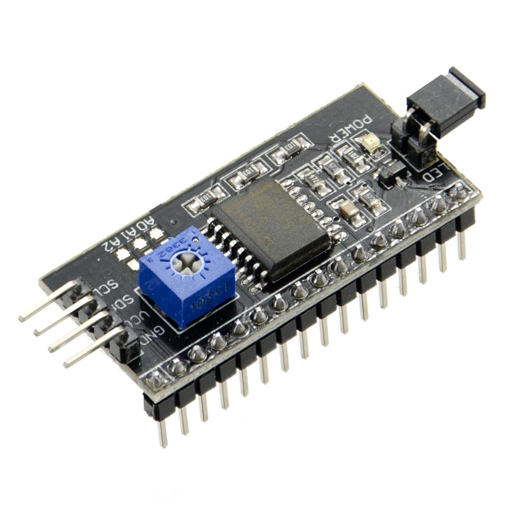
I2C backpack
Below is a mockup session.
Next todo:
Add more hardware (like buttons) to the RPI
Configure an Accesspoint on this Rpi for other devices to connect to
Install a local Mqtt broker, which connects secure to my internet facing broker
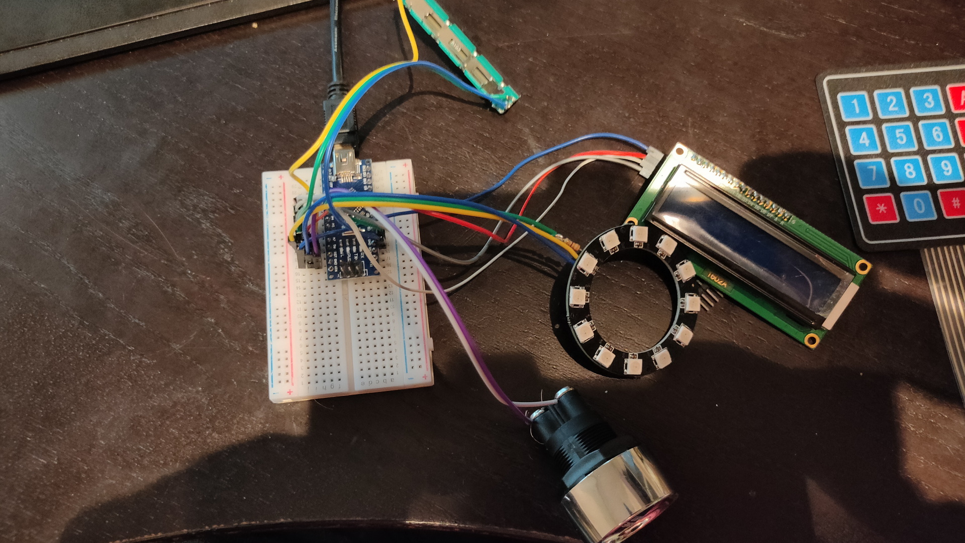
I’ve been working on some modular gadgets which can be combined to make a complete puzzle.
I like games like Keep-talking-and-nobody-dies. (Which is a computer game, but you have to play it with multiple persons and a physical “manual” Great fun!) https://keeptalkinggame.com/
And i like real escape rooms. There are some puzzle “rooms” you can buy in the game store, it is okay but many are for single use only.
I’ve been following some people on youtube, i saw some great ideas but not a remote over the internet using physical knobs and switches.
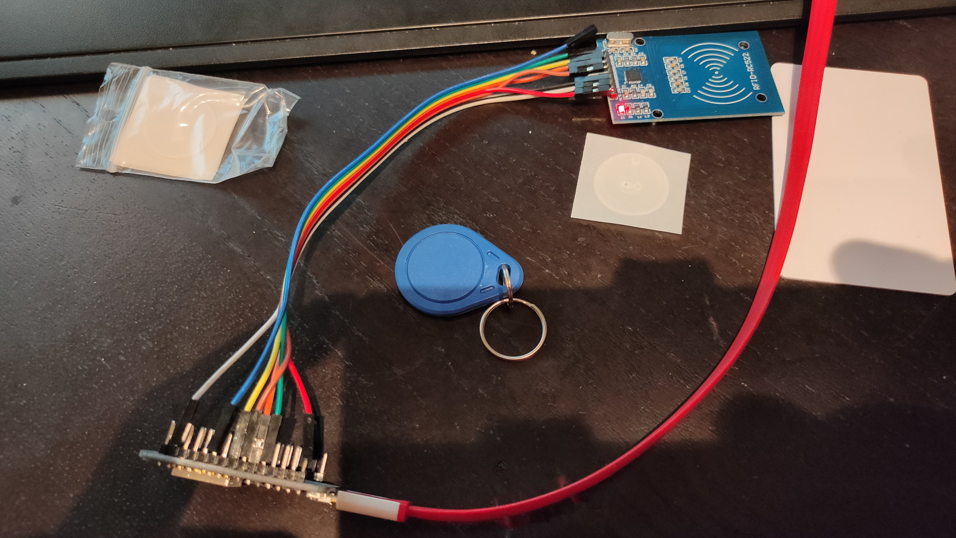
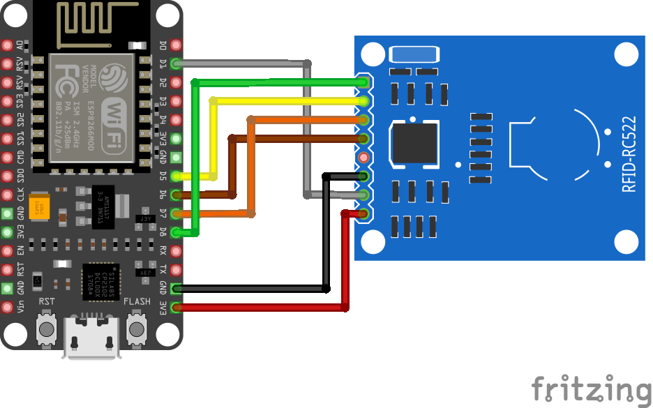
This is a RFID reader with an old Amico Esp8266 Arduino. It sends RFID information to the MQTT broker
Some other tools ‘n knobs .. and stuff
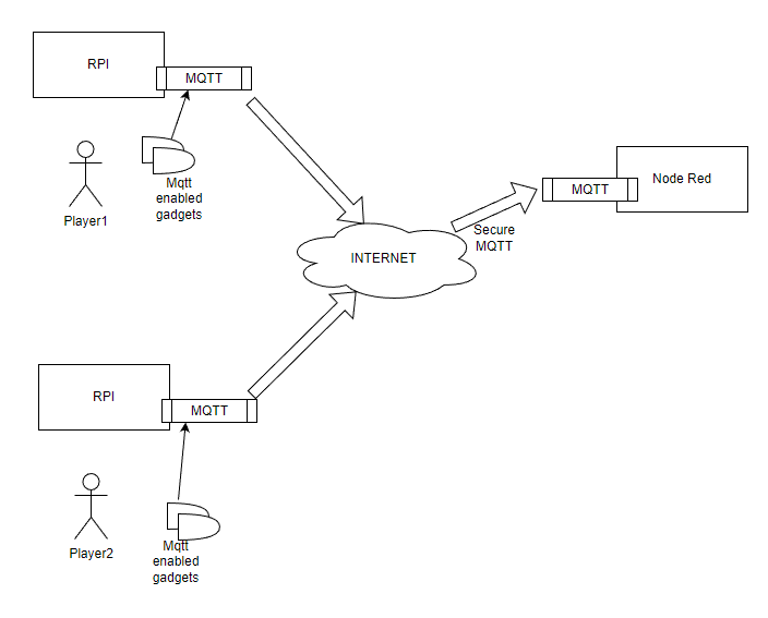
I want to use Adhoc Wifi and a Mqtt/Nodered setup which uses a mqtt over the internet to get people (and their knobs) connected
I already got a lot of test schematics
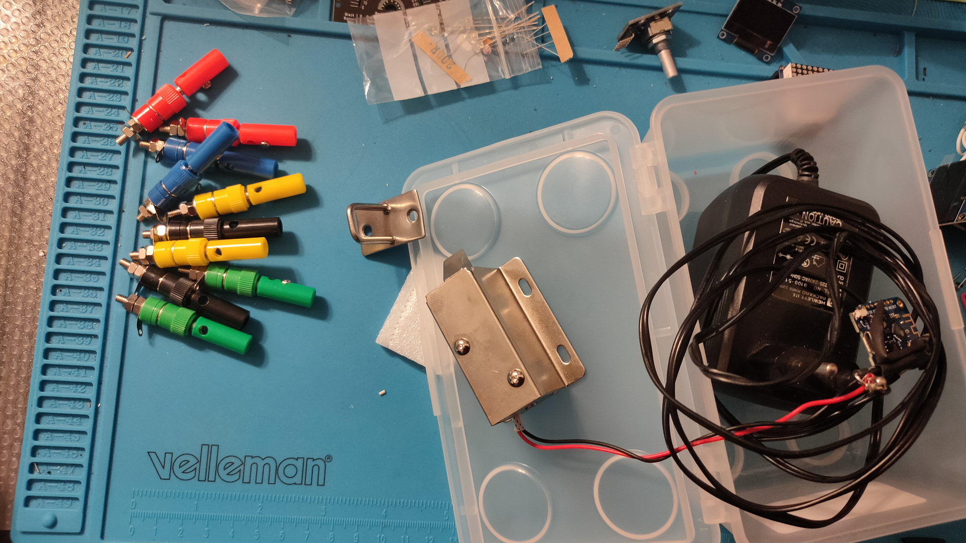
Left part of the “connect the wires puzzle” right a solenoid electrical lock)
I never look in the mirror, so why do i need one? The mirror foil was already ugly in the corners. There were bumps. Never finished a proper interface
This one was made using a touch screen, so there are always fingerprints you could see
I’m going to use the display for an in-house small Escape Room idea i have.
Only the time part still worked, but i could not find the right cables for the touch part. The buttons displayed are meaningless anyway 🙂 Just a mockup
Mirror part was done using a Safety/One way mirror foil. Cut a part as large as you screen, spray a little water and stick it on.
At some point i displayed Dashticz on there. Apparently i started playing with a magic mirror setup in 2015, according some timestamps of code on my fileserver.
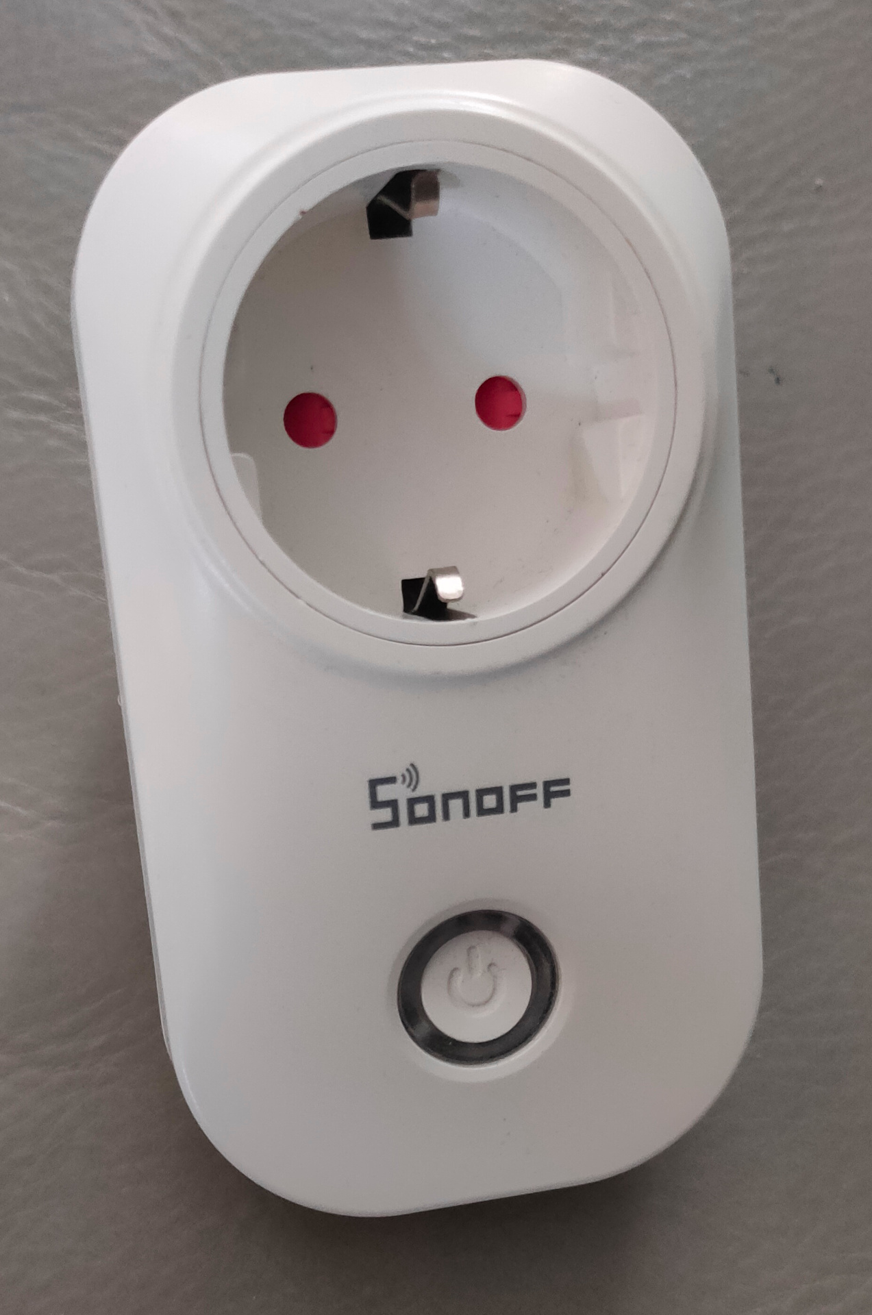
I previously had these smartplugs flashed with EspEasy (I hate cloud enabled devices) I will post something about flashing these and others. Maybe … because you can find a lot of information on the internet. But i’ve used several tools, and made tools for this process. ( Raspberry Zero mobile tool and 3D printed PCB holder for example)
Well ..
I was using these devices in our previous home using curl commands and on a main wifi network. So i have to change the SSID and migrate from Espeasy to ESPhome so i can use these devices with Home Assistant.
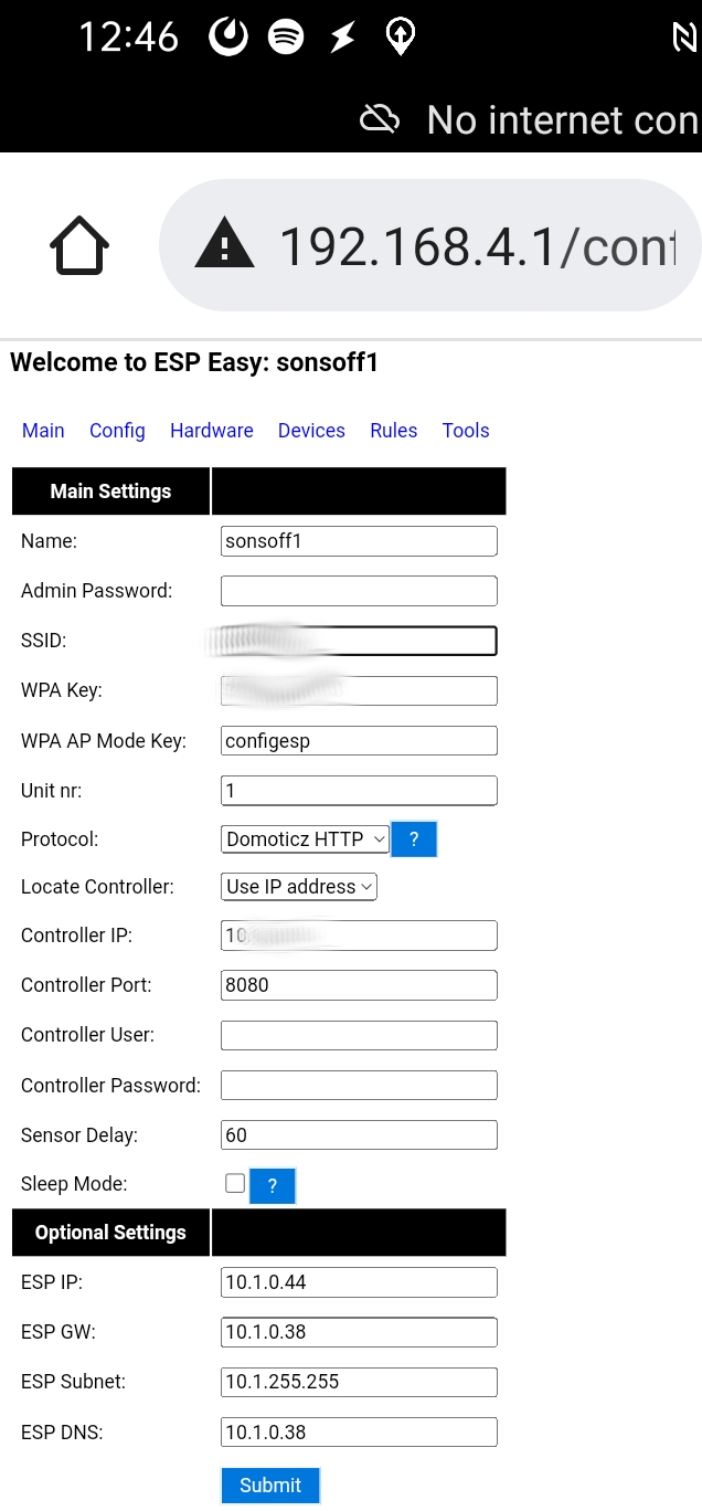
Step 1 : Start in Access Point mode and migrate to my current Wifi Iot network.
Using my phone i made the necessary changes.
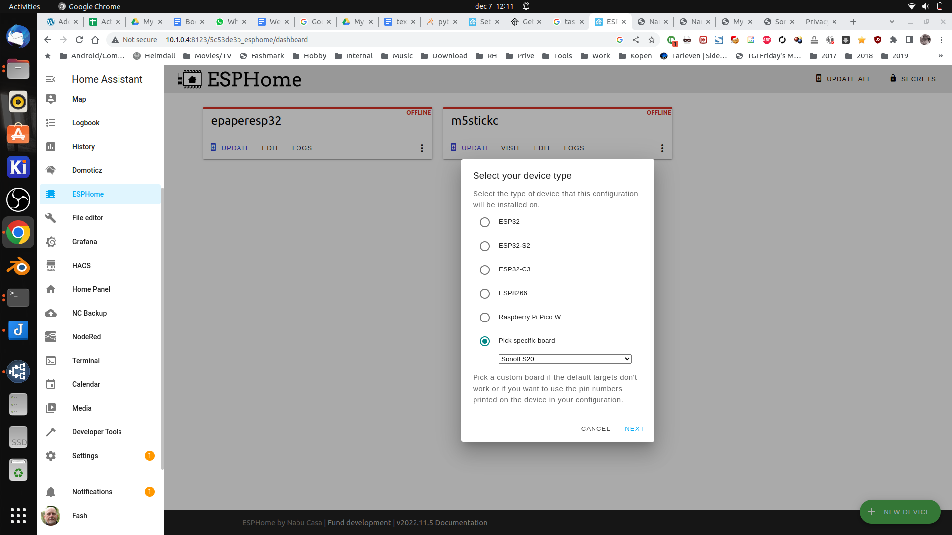
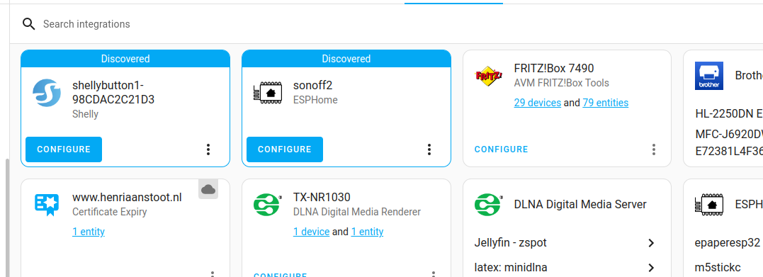
Goto HomeAssistant and ESPhome (you need to install this first via HACS) Press the green + Add device and give it a name
Next select the device type (Sonoff S20 in this case)
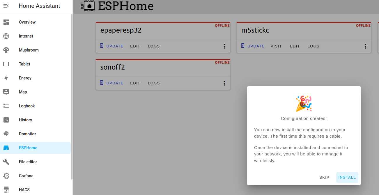
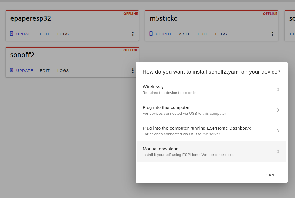
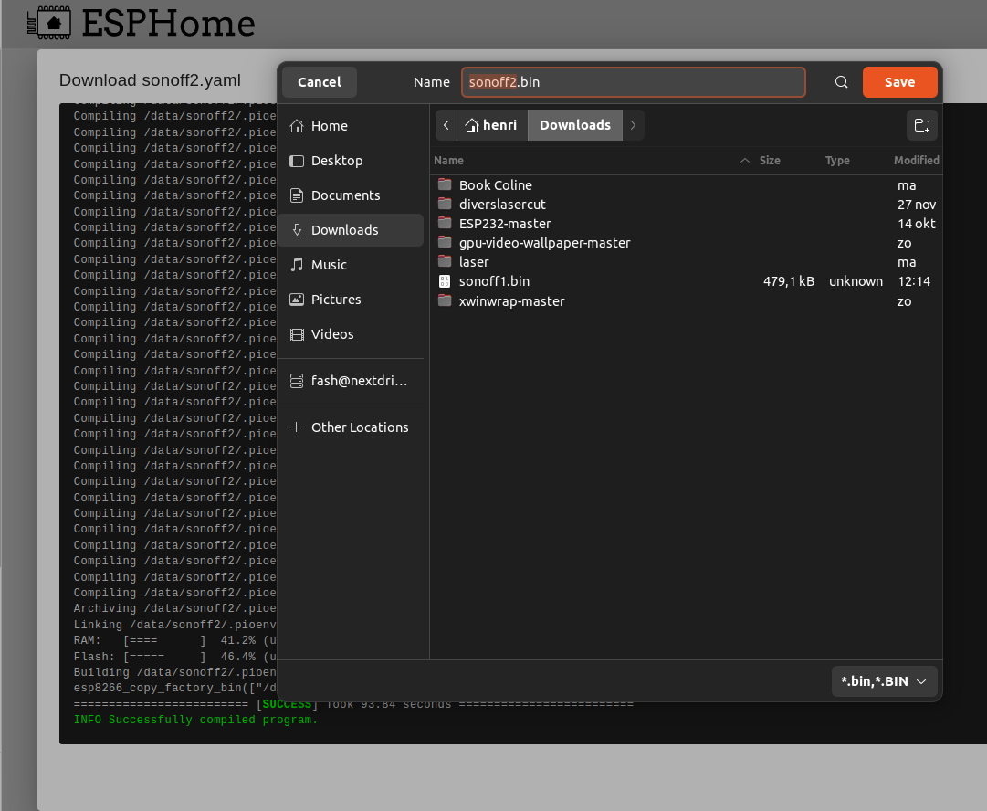
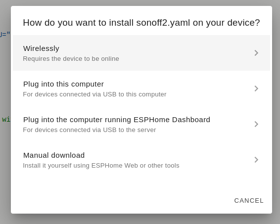
Press install and select manual download
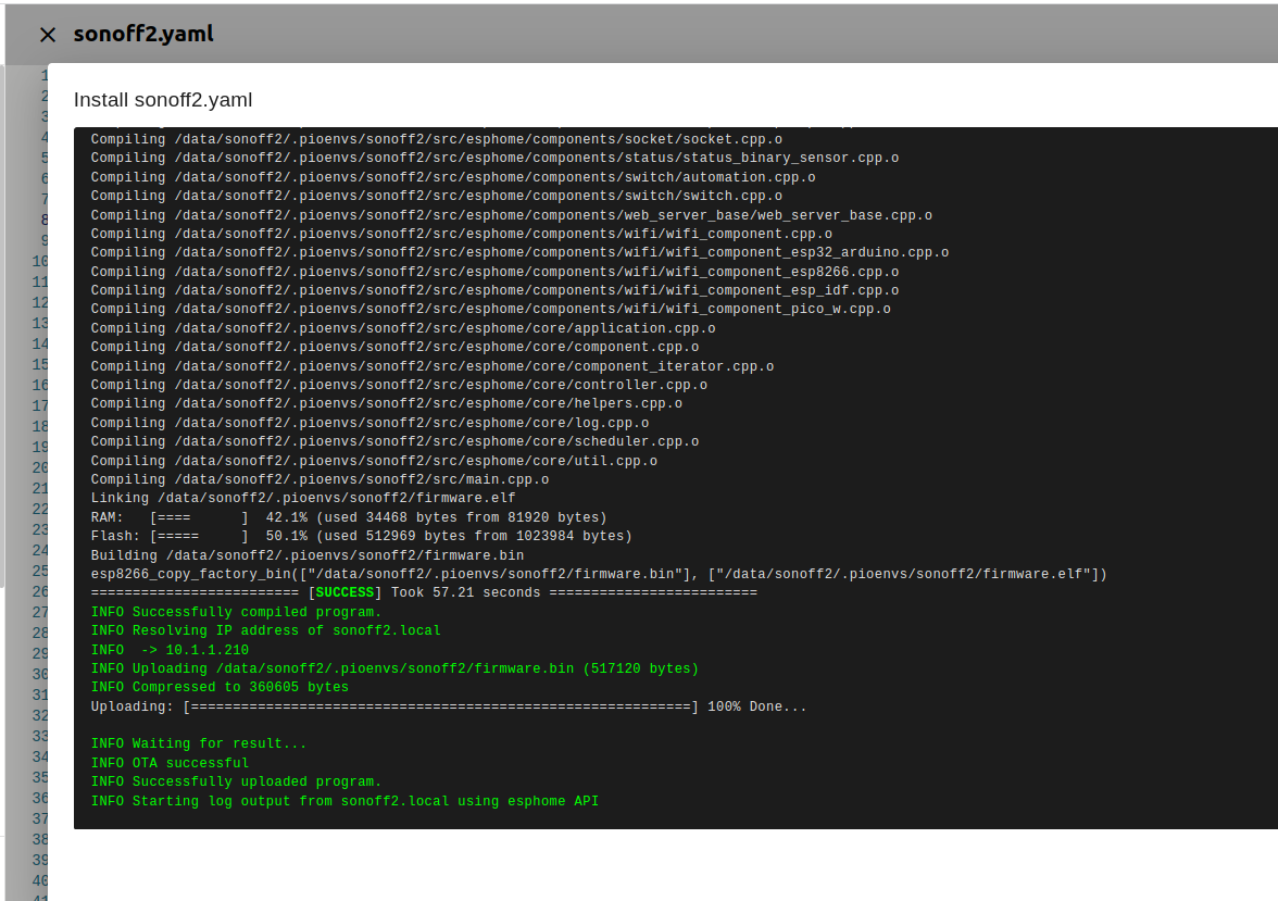
Above will compile a binary for the Sonoff device.
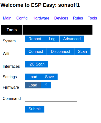
Go back to your Sonoff interface and go to the tools tab. We can reflash the device without connecting this with wires to our computer.
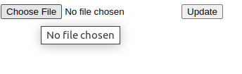
Press Firmware load and select your downloaded binary
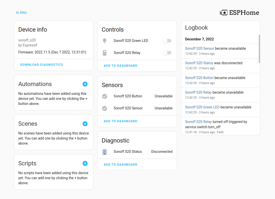
Back in HA it should say “online”
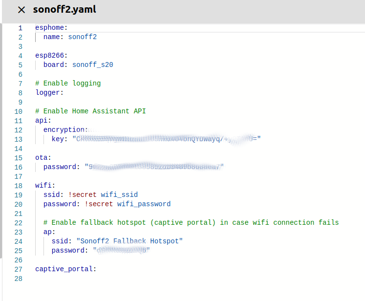
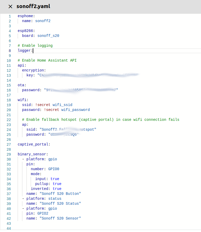
Pressing edit gives us a config page. Nothing works .. yet We need to add some yaml entries. ( use https://esphome.io/devices/sonoff_s20.html )
binary_sensor:
  - platform: gpio
    pin:
      number: GPIO0
      mode:
        input: true
        pullup: true
      inverted: true
    name: "Sonoff S20 Button"
  - platform: status
    name: "Sonoff S20 Status"
  - platform: gpio
    pin: GPIO2
    name: "Sonoff S20 Sensor"


switch:
  - platform: gpio
    name: "Sonoff S20 Relay"
    pin: GPIO12

output:
  # Register the green LED as a dimmable output ....
  - platform: esp8266_pwm
    id: s20_green_led
    pin:
      number: GPIO13
      inverted: true

light:
  # ... and then make a light out of it.
  - platform: monochromatic
    name: "Sonoff S20 Green LED"
    output: s20_green_led
BeforeAfter
Now press install
Now we can use wirelessly to upload the config
After this the device can be discovered by HA
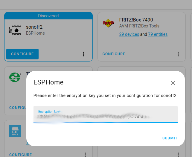
Click add, and use the encryption key found in the yaml config to add
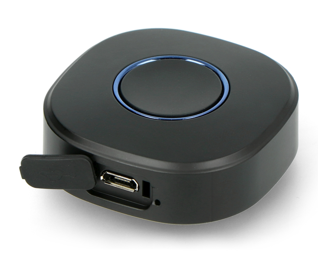
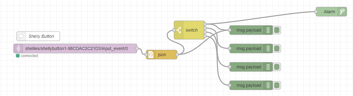
For a while i’ve been using the wireless shelly button for all kinds of notifications. Most of the time i like to use it as a kind of alarm/need-help-now button.
The f*ckin’ awesome button i’m talking about (pictured above) is a small (45x45mm 16mm height) button, which can connect to your wifi and send MQTT messages. It even has a strap thingy to attach it to your keychain,
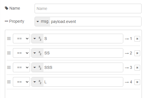
Four types of messages:
short press
2x short presses
3x short presses
and long press
When using pushover, you can push alarm and messages to your android (even overriding mute/silent if you configure it that way!)
Configuring the button: https://www.shelly.cloud/documents/user_guide/shelly_button_1.pdf
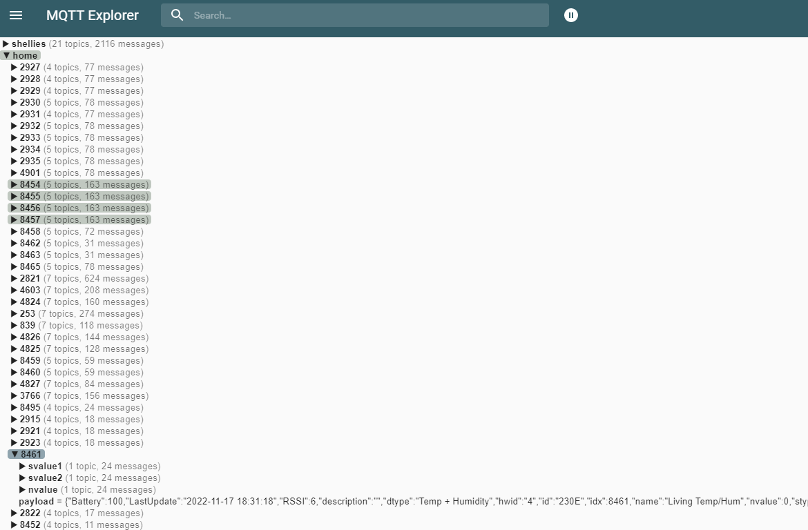
I’m using domoticz as a 433->mqtt bridge, and some virtual devices i can toggle with curl (bash scripts)
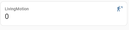
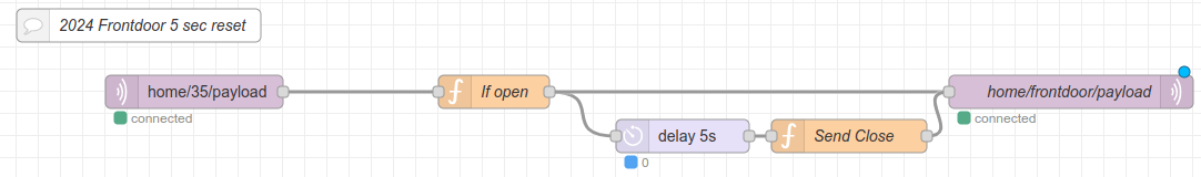
I needed to make a custom 433 door sensor in Home Assistant with toggles to OFF after a few seconds. (There is NO off signal in this cheap sensor i’m using)
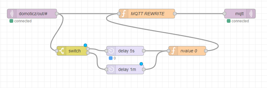
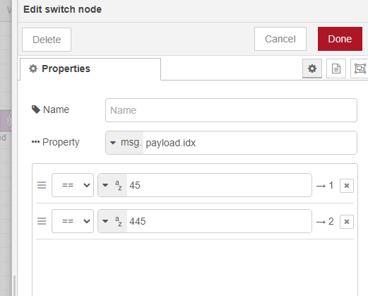
I’m changing the payload complete, to have a payload which matches the device class for door: (state with on/off) It was nvalue = 0/1
(Whenever the IDX changes, I only have to update this Nodered part) HA won’t notice the change.
var nvalue = msg.payload.nvalue;
msg.payload = {};
if(nvalue == 1)
{
msg.payload.state = "ON";
return msg;
}

AND after 5 seconds

msg.payload = {};
msg.payload.state = "OFF";
return msg;
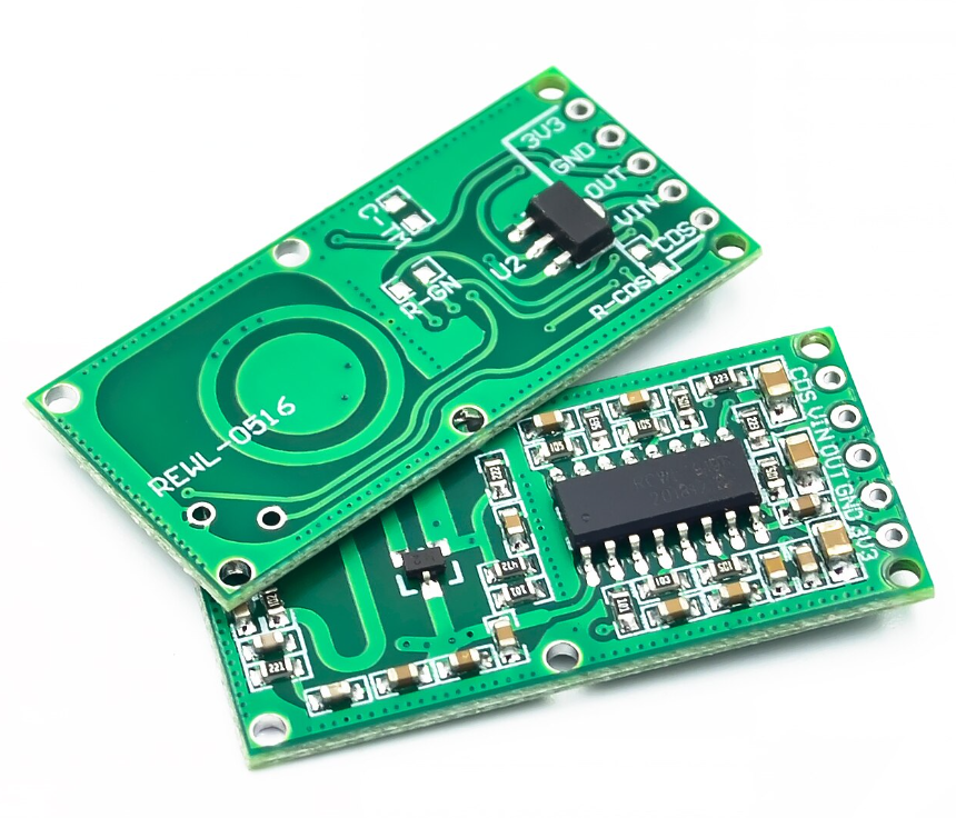
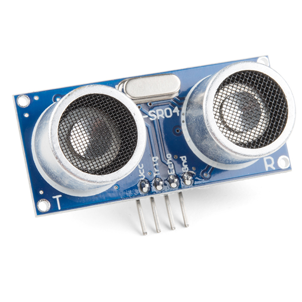
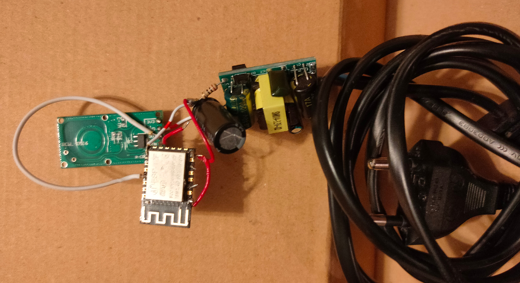
Last year i was playing with this radar module also, but today i made a version with MQTT and a linux client. (There is a project on the internet which uses a HC-SR04, and a arduino connected to the Laptop. This setup is more sensitive and no need for a usb thinghy.)
HC-SR04 module (ultrasound)
Last years version, using a micro transformer and a ESP-12
When using MQTT i can integrate this in HomeAssistant, Domoticz, NodeRed and more. But i’ve written a python script which runs on my Laptop. For example i can: Kill vlc, change to my work desktop, stop sound output and lock the screen. (everything you can script)
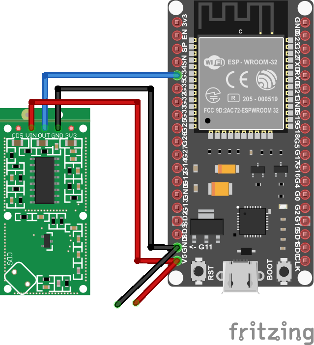
I wanted to have a “mobile” version of the sensor so i can place it anywhere. (Frontdoor, gardengate, candydrawer 🙂 )
These modules are very cheap, but do their job well!
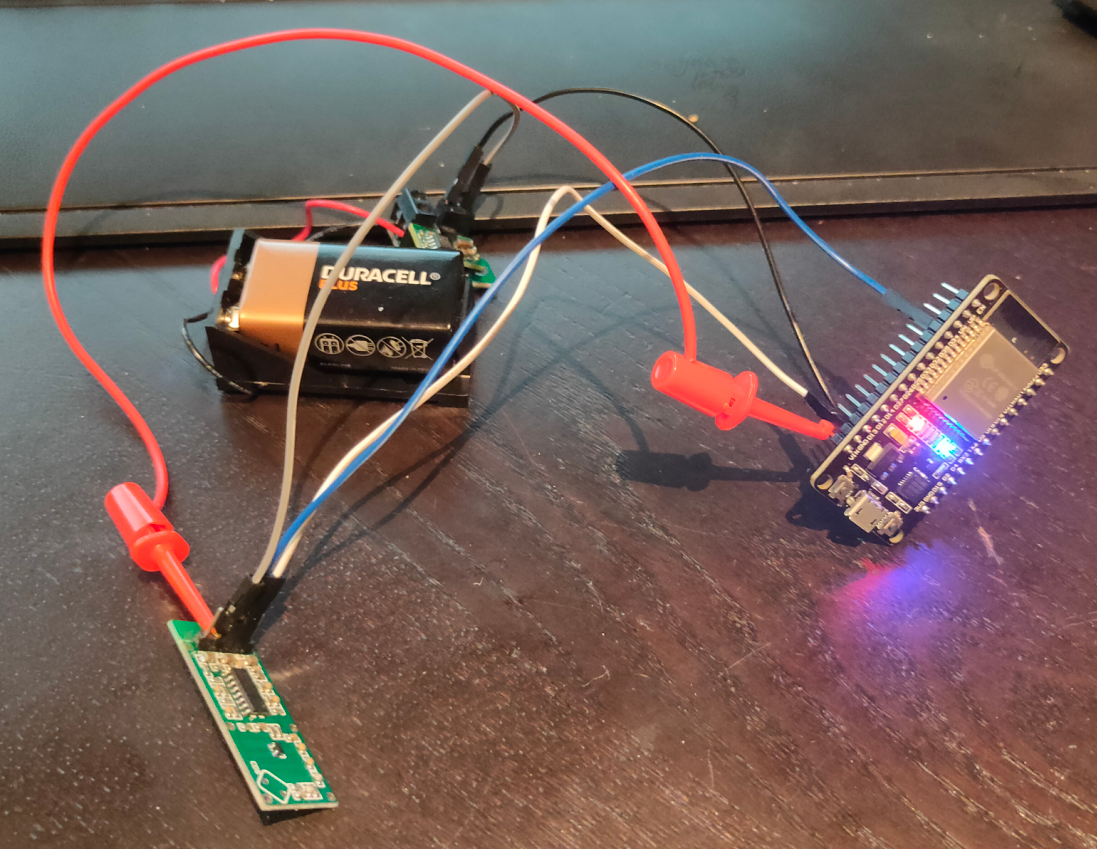
I’ve used a Wroom ESP32 and a BattBorg together with the module, that’s it.
Below shows the speed of detection, and sending though the network
Python script which does a lock-screen using XDOTOOL
from paho.mqtt import client as mqtt_client
import subprocess
import time

broker = 'MQTT-SERVER'
port = 1883
topic = "radar/state"
client_id = "radarclient"

def connect_mqtt() -> mqtt_client:
    def on_connect(client, userdata, flags, rc):
        if rc == 0:
            print("Connected to MQTT Broker!")
        else:
            print("Failed to connect, return code %d\n", rc)

    client = mqtt_client.Client(client_id)
    client.on_connect = on_connect
    client.connect(broker, port)
    return client

def subscribe(client: mqtt_client):
    def on_message(client, userdata, msg):
        state = msg.payload.decode()
        print (state)
        if state == "1":
            subprocess.Popen(["xdotool","key","Super_L+l"])
            time.sleep(30)


    client.subscribe(topic)
    client.on_message = on_message

def run():
    client = connect_mqtt()
    subscribe(client)
    client.loop_forever()

if __name__ == '__main__':
    run()
change subprocess.Popen([“xdotool”,”key”,”Super_L+l”]) into subprocess.Popen([“switchdesktop”]) to run a script named switchdesktop
#!/bin/bash
# This is the switchdesktop script, it goes to the next screen using winows-page-down combo
xdotool key "Super_L+Page_Down"
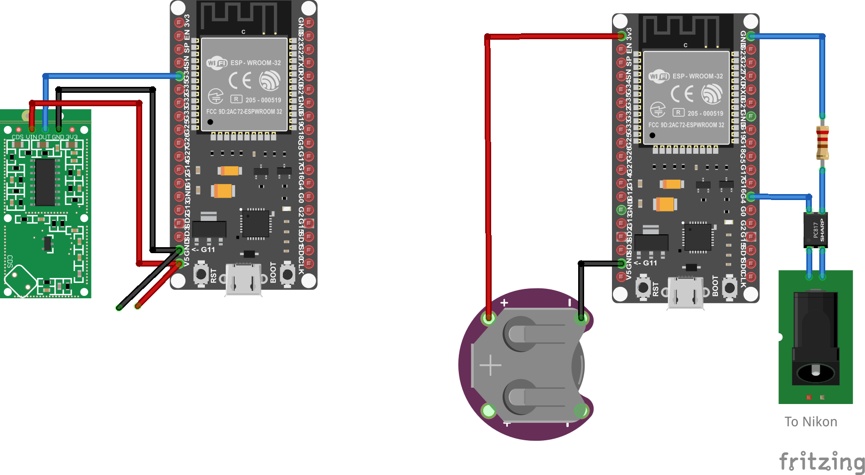
Todo:
3D print a case Make a version which becomes a Access Point. Then make another arduino setup which controls my Nikon. So it can act like a wildcam (offline)
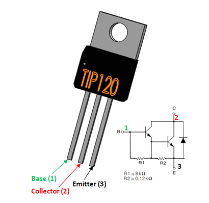
Something like below, using a optocoupler ( i still got some leftovers from my doorbell to gpio-pin project.)
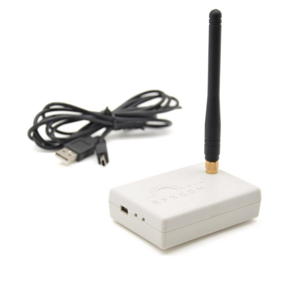
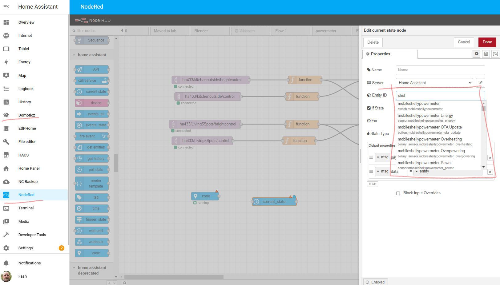
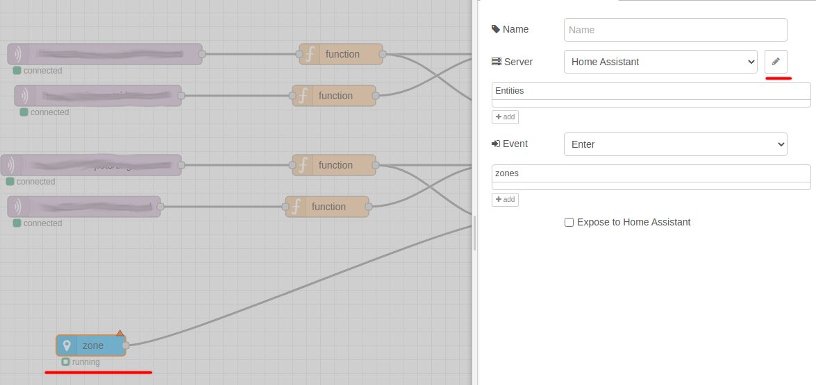
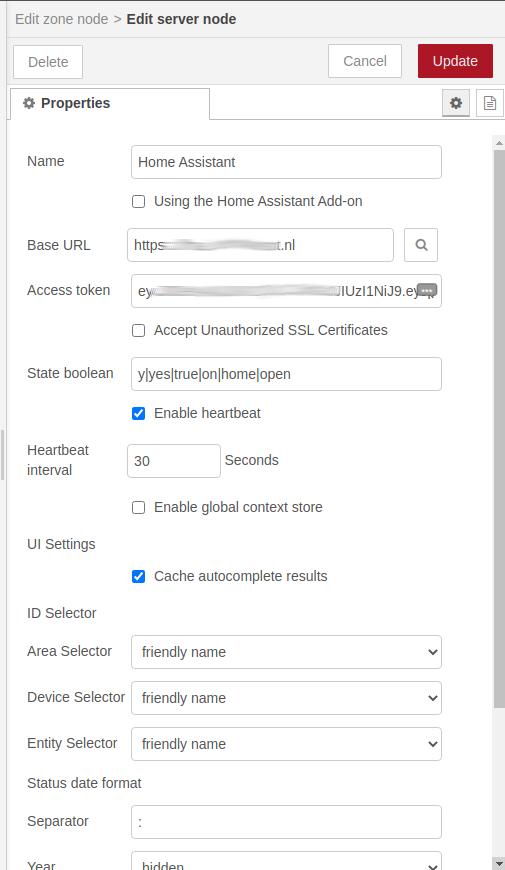
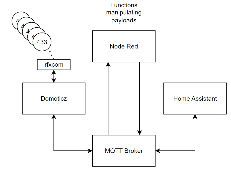
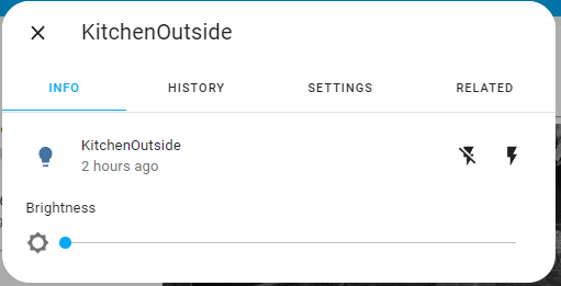
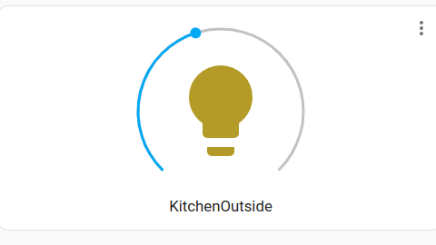
Getting 433Mhz dimmers working under HA is a pain in the *ss.
After moving my Rfxcom from domoticz to HA, there was still no good way to add dimmers. I’ve tried adding switches and migrating them to lights, but it didn’t work.
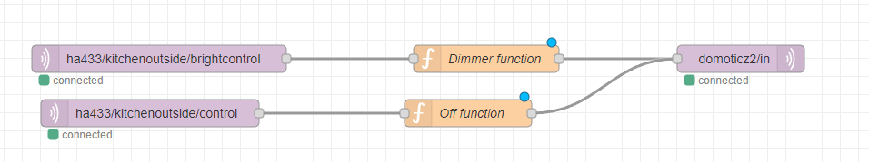
So i took another approach.
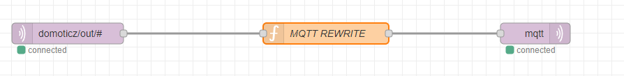
Domoticz has a good 433 to mqtt plugin. So i used NodeRed to talk to HA and Domoticz via MQTT.
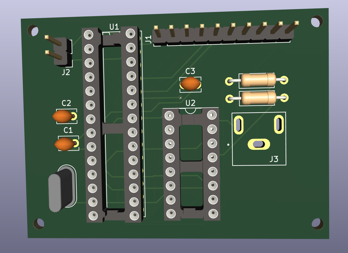
Composite video print designed and ordered from china.
Changed some vlans in my network. I need to think of a way to extract/migrate domoticz 433 info into a new instance. For example .. i’ve got some instances in my device list which are only being controlled by domoticz, there is no remote i can reuse.
Tried welding again, because i could not do it for a long time, i noticed i have to practice again after 2 years. (I’ve got a dedicated power outlet outside now .. 🙂
Last 8mm films work done. (Converted all of my dad’s old 8mm reels)
Designed a hidden remote cabinet, holding remotes out of sight for the occasions when automation doesn’t work.
Designed also a wooden wall with hidden cabinets in our bedroom.
Repaired a Gardena Leafblower .. again!
"If something is worth doing, it's worth overdoing."