I saw some LED strip dividers on Aliexpress, next year it’s going to have a star on top.
Like this….
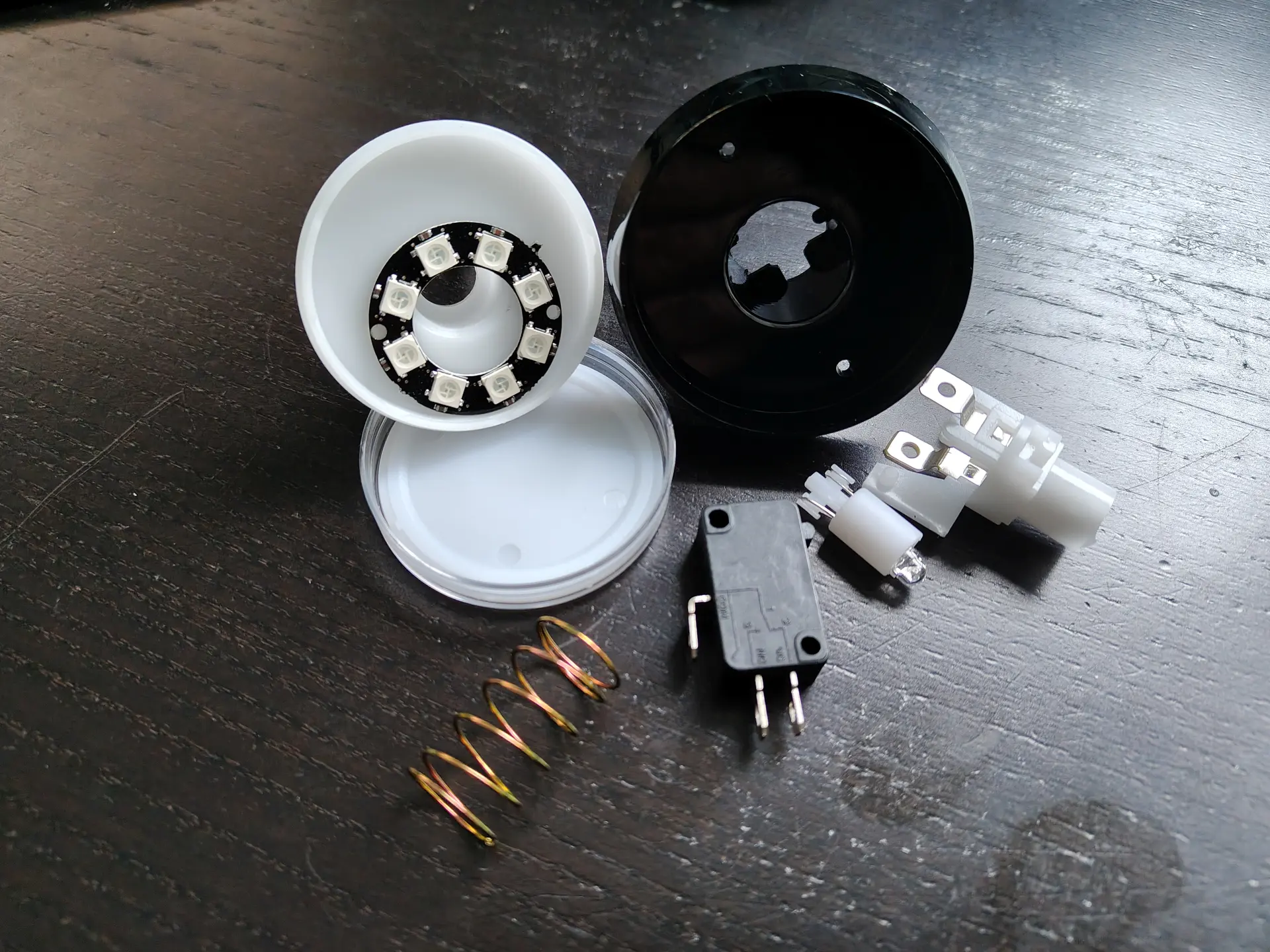
Another LED related project I started today is a Whack-A-Mole game with multiple levels. For this I need to convert a simple arcade button to a programmable multicolor version.
From single white LED to multi color, programmable.
Another game in the making is a Red Light – Green Light game. Like in Squid Game. This will use a lidar and a python script which detect movement using a camera.
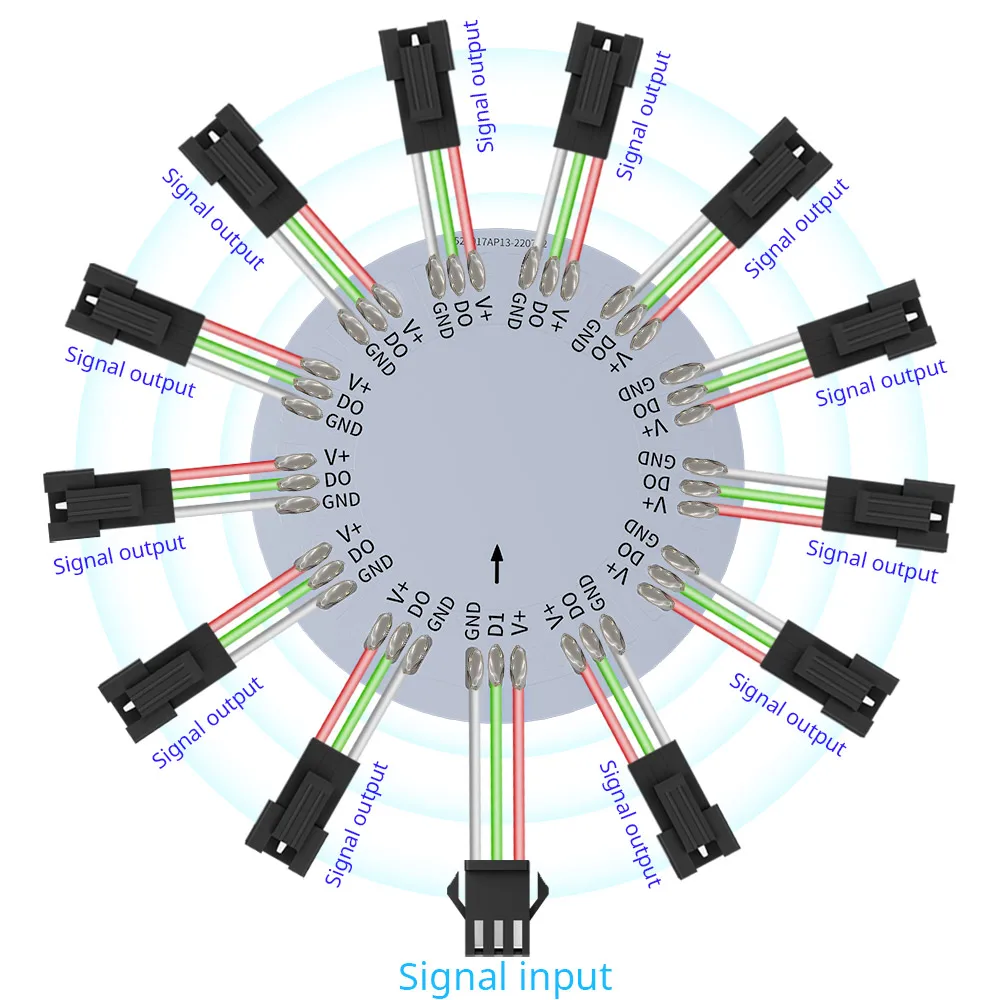
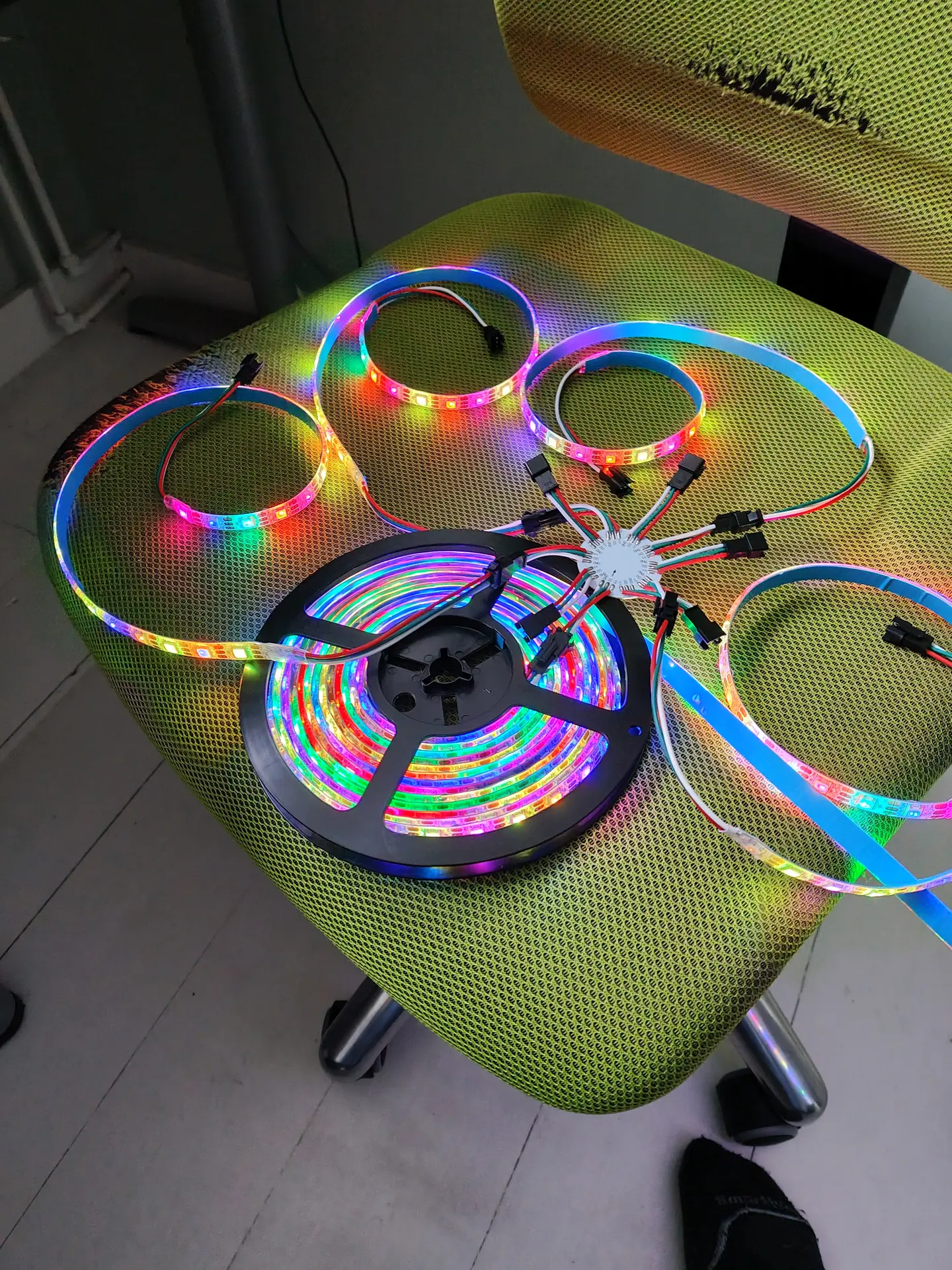
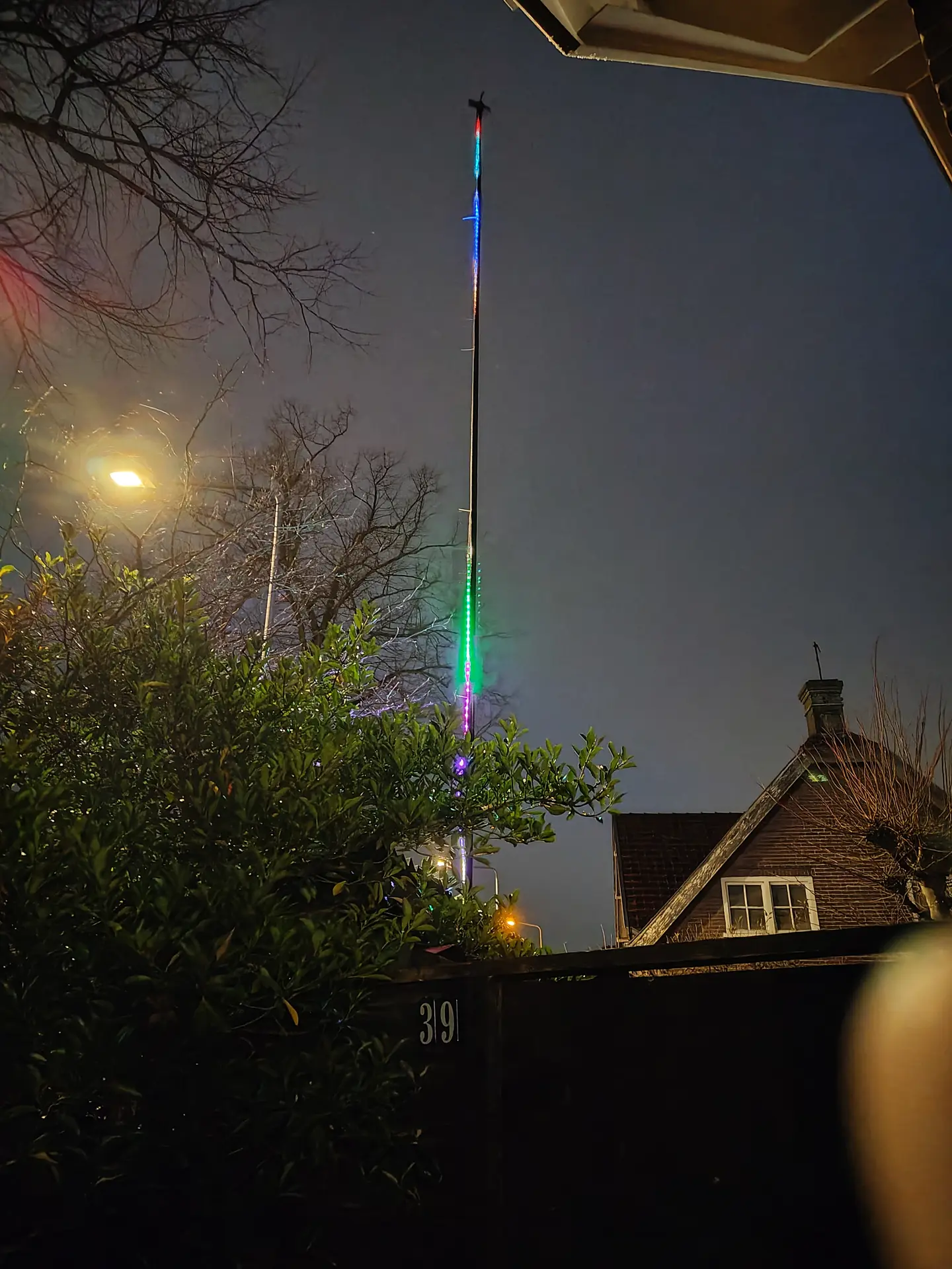
It gave me the idea to make a pole which displays digital “fireworks” using leds. Fireworks are becoming illegal the next year in the Netherlands, I think.
So why not going digital? 12 Meter pole, 300 Leds.
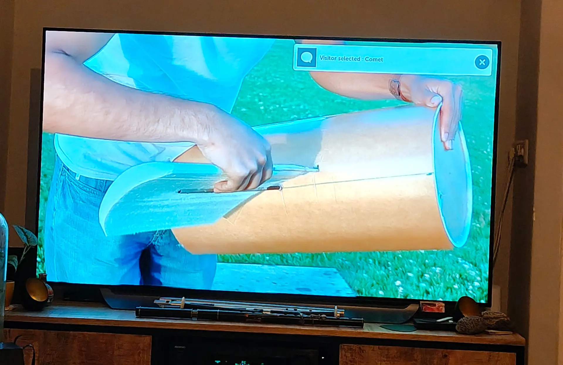
There is a QR code and a website link mentioned on a page at the gate. 10 presets to select via a website.
Notification on my TV
While waiting for the first visitor I made a magnetic game. Using a bunch of magnets, and 3D printed hexagon rings. Two players try to place magnets in a small area without moving the others. If magnets slam together, you have more pieces to place. (Below, last player has to take those 6 pieces)
These are amazing, I’m using this in my Lab to switch on my big LED panel. You don’t need to move, it will detect human presence. Another one I’m using in my living room. It can power off all media at night (like TV, amplifier and lights) It’s part of my home alarm system when we are away.
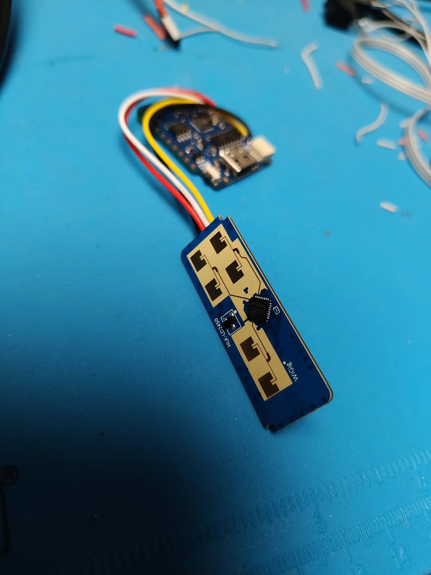
Now I got a new MMWave sensor (hlk-ld2450) , it can detect up to 3 persons and their location.
Screenshot from a Bluetooth phone app reading the sensor.
We are planning to redo our garden. And I am making a water and light plan for it.
I thought I could do it myself using 12V and RS485/Modbus.
So these are my plans. (NOTE, this is a work in progress)
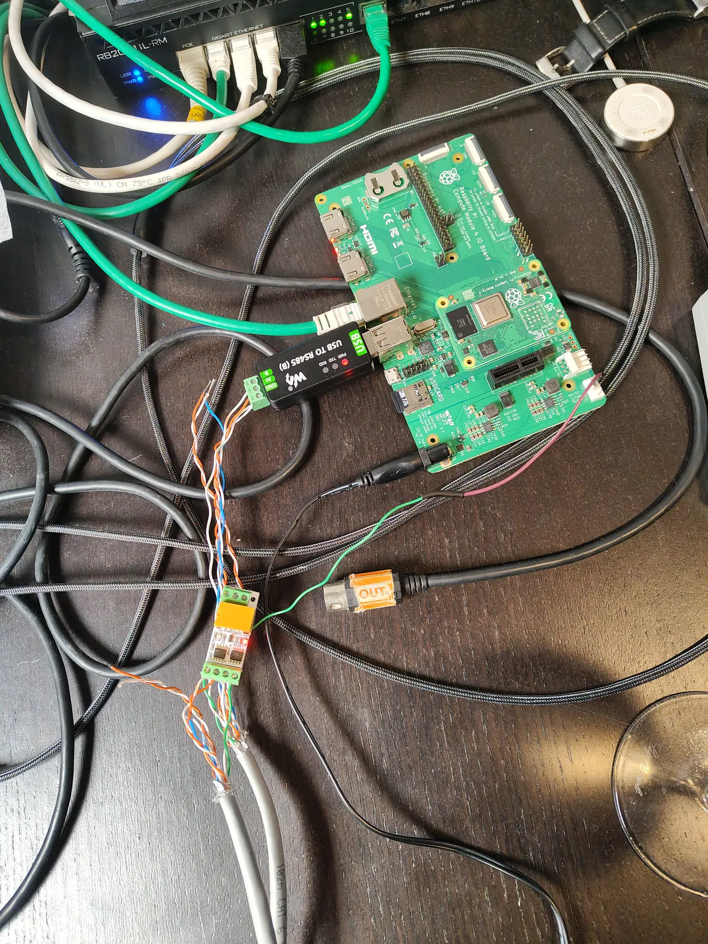
I’m going to put 4-wire ground cable in our garden, and a RS485/Modbus master controller in my shed. 4 Wires will have 12V low voltage, ground and RS485 A/B wires. This way I can control till 64 devices on a single cable.
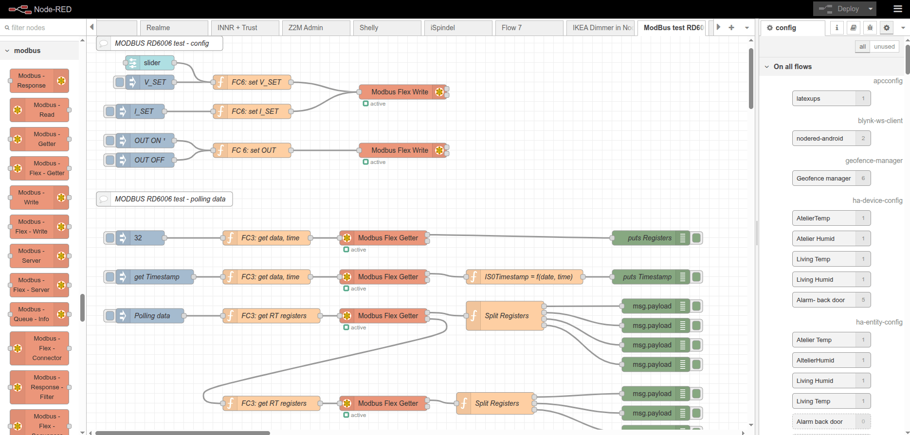
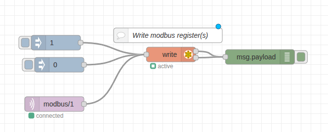
Below, a USB stick to connect the RS485 cables to a Raspberry Pi? Software is probably going to be a NodeRed instance connected to Home Assistant.
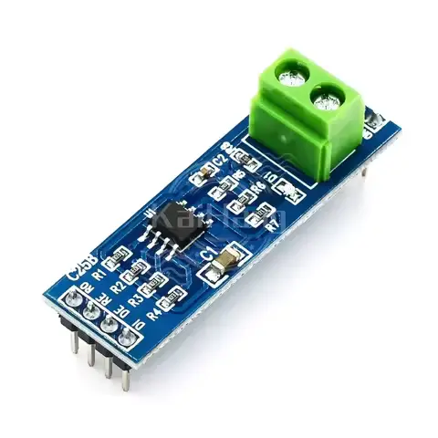
On/Off lights using a RS485 board and relay. These can be bought on a single PCB and can control 220V. I am probably going to use generic outside lamps and refit them for 12V led or 220v, with those RS485 controllers.
Test PCB
The above left part will be encased in resin or alike. Right PCB is for testing only.
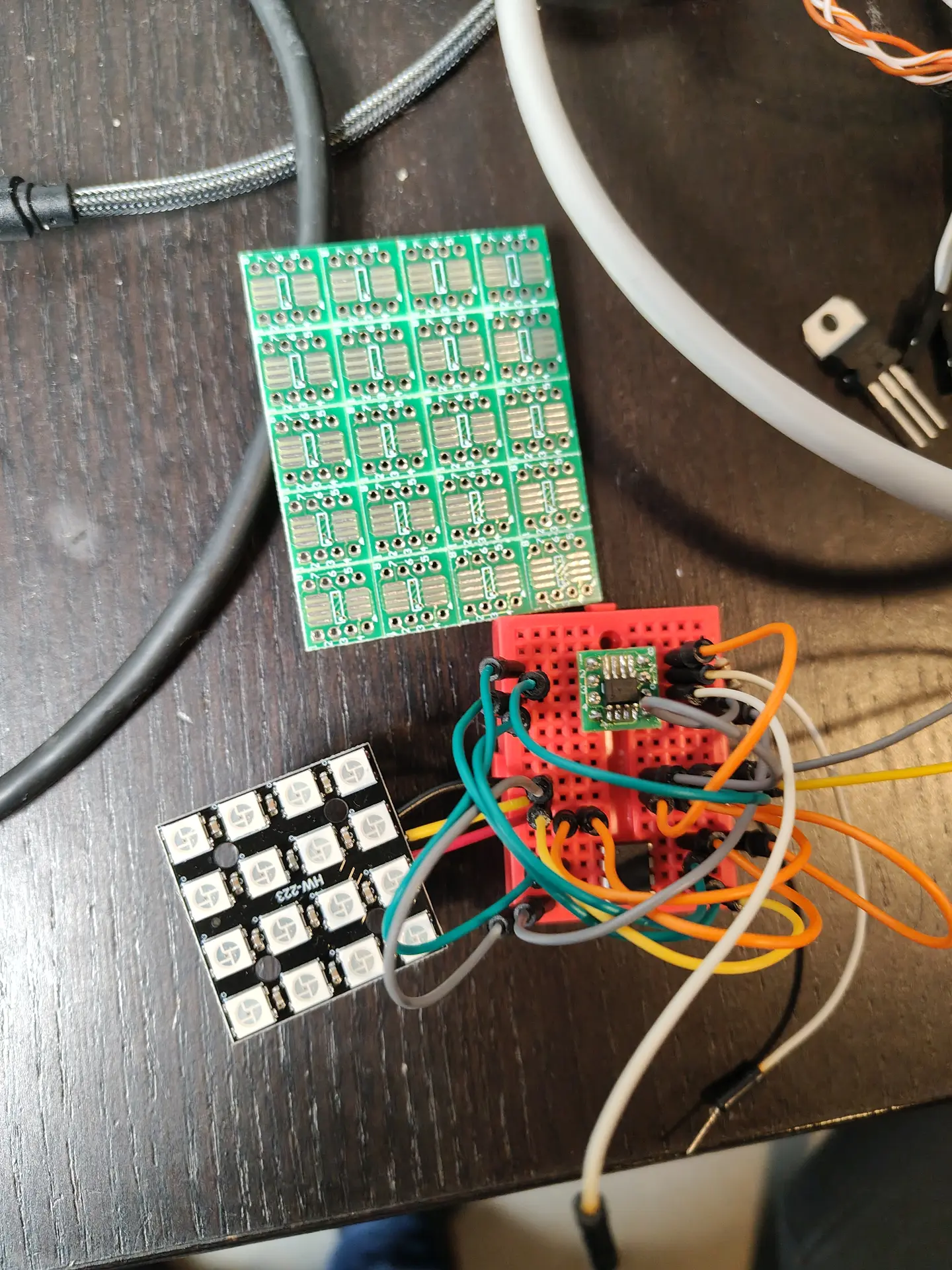
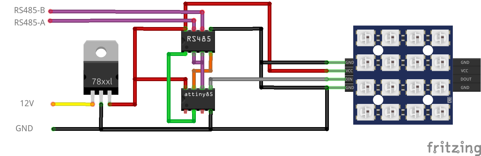
For dimming RGB lights, I made the below design.
NOTE: This needs 120ohm end resistor and capacitors over the 7805.
12V to 5V using a 7805, RS485 8pin DIL/DIP and a ATTiny85 8pin DIL/DIP. Plus a 4×4 RGB Matrix. These also encased in resin.
More information on the ATTiny85 and programmer can be found here:
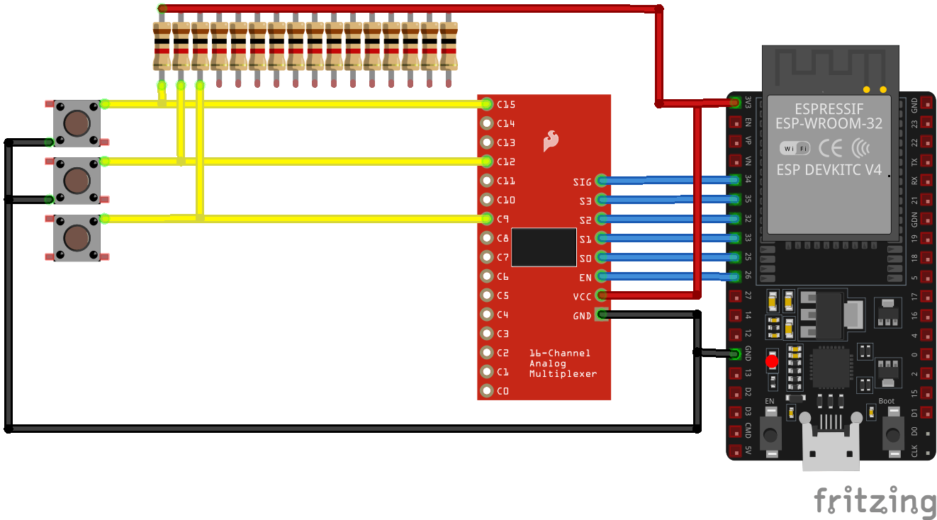
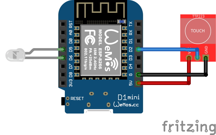
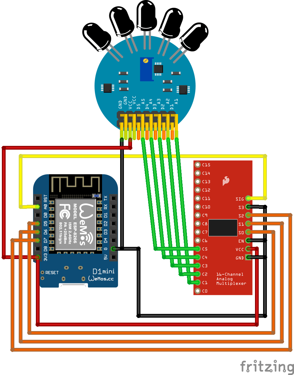
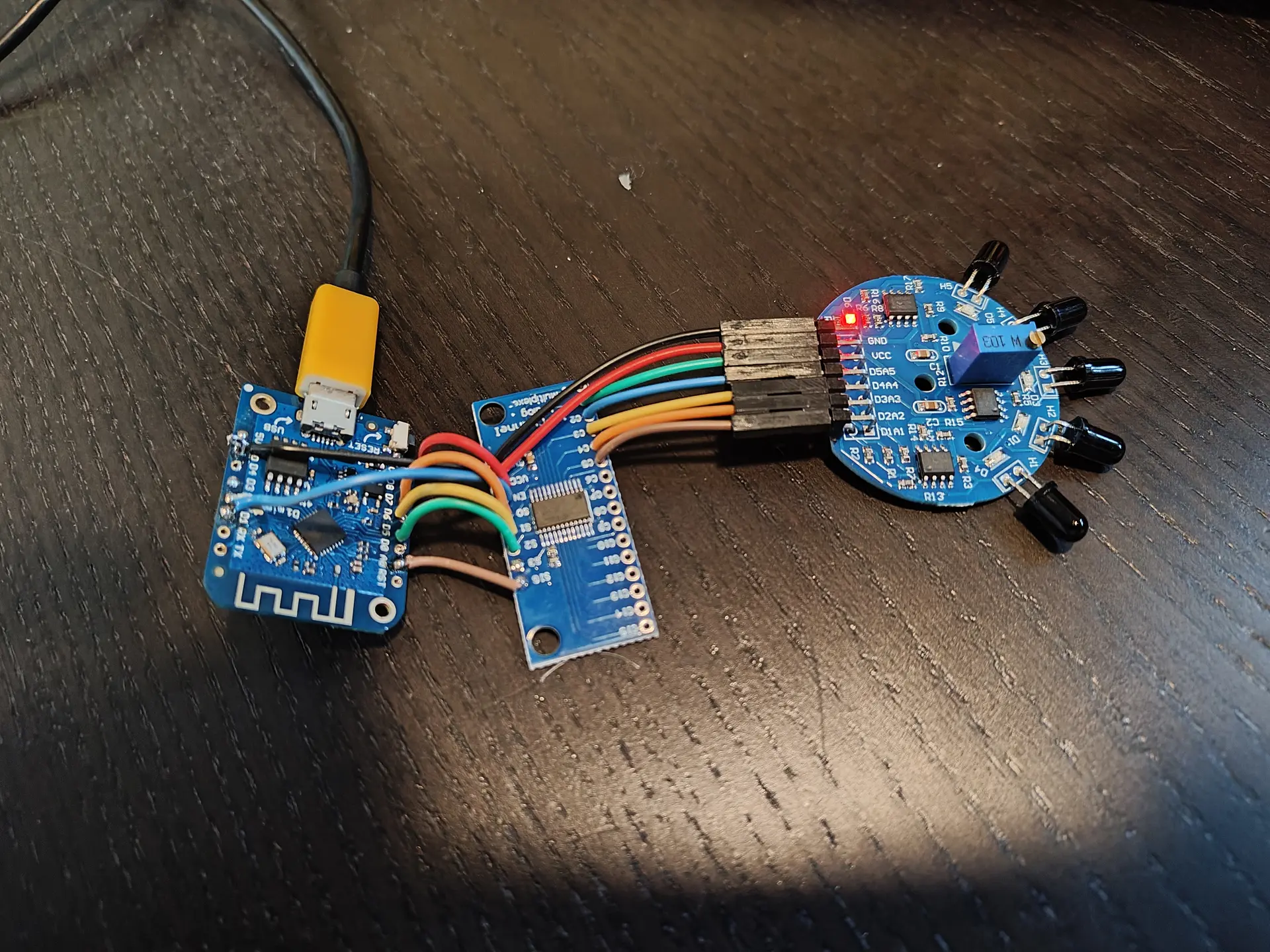
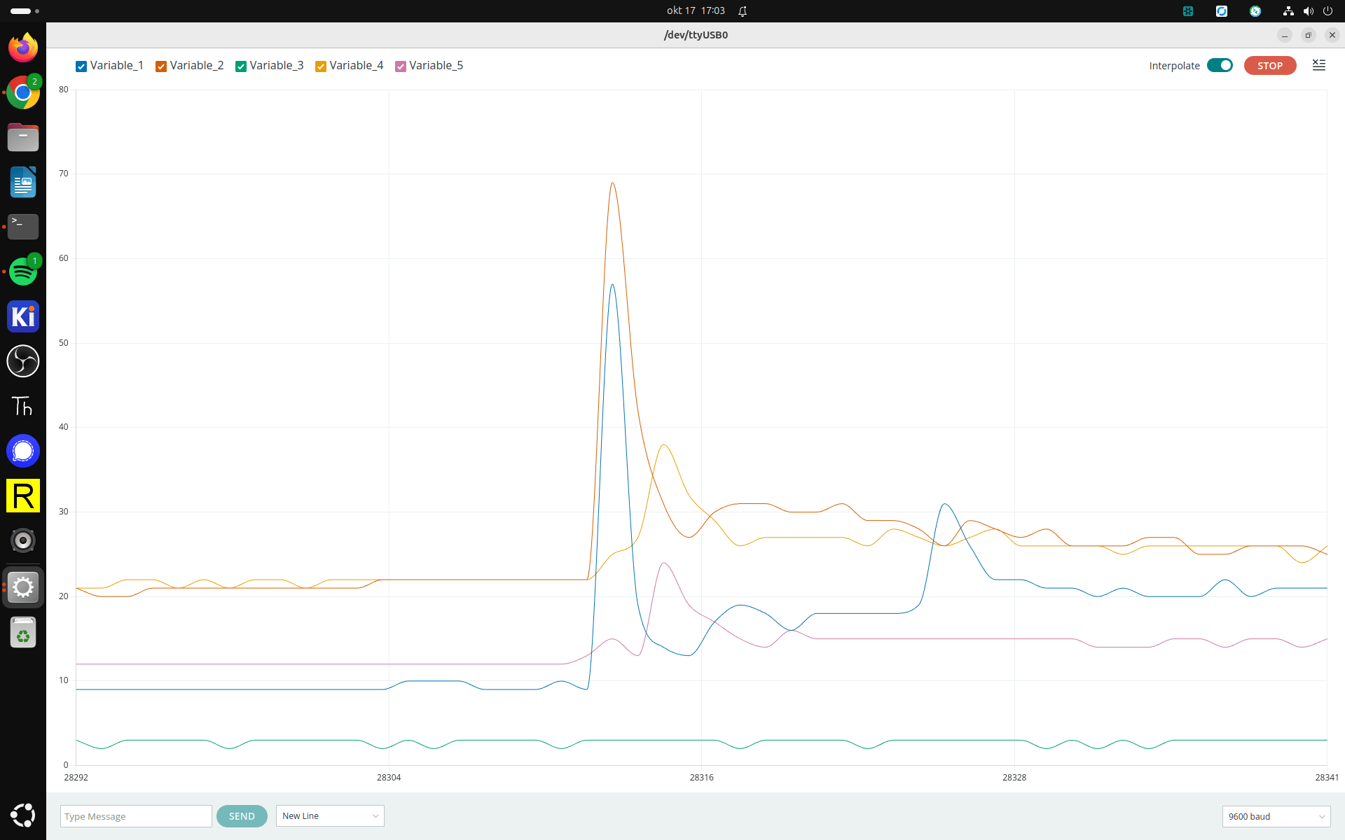
The plan is to make a flame sensor, with in combination with my presence sensor will alert me when we leave the room and candles are on, give us a notification.
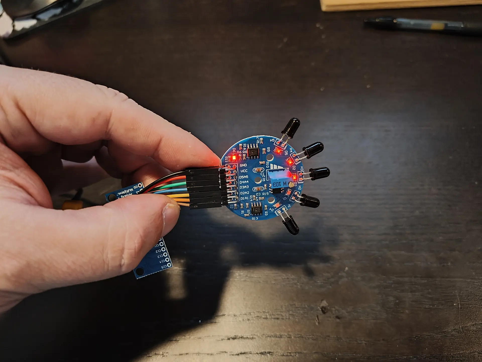
Above is the schematic. A Wemos mini (left over from another project), an analog multiplexer and a cheap 5 times flame detector. There is a potentiometer on this board to change the sensitivity.
Search “Infrared Ir Flame Sensor Detector Fire Detection Module 5 Channel” on Aliexpress. These are 1 euro.