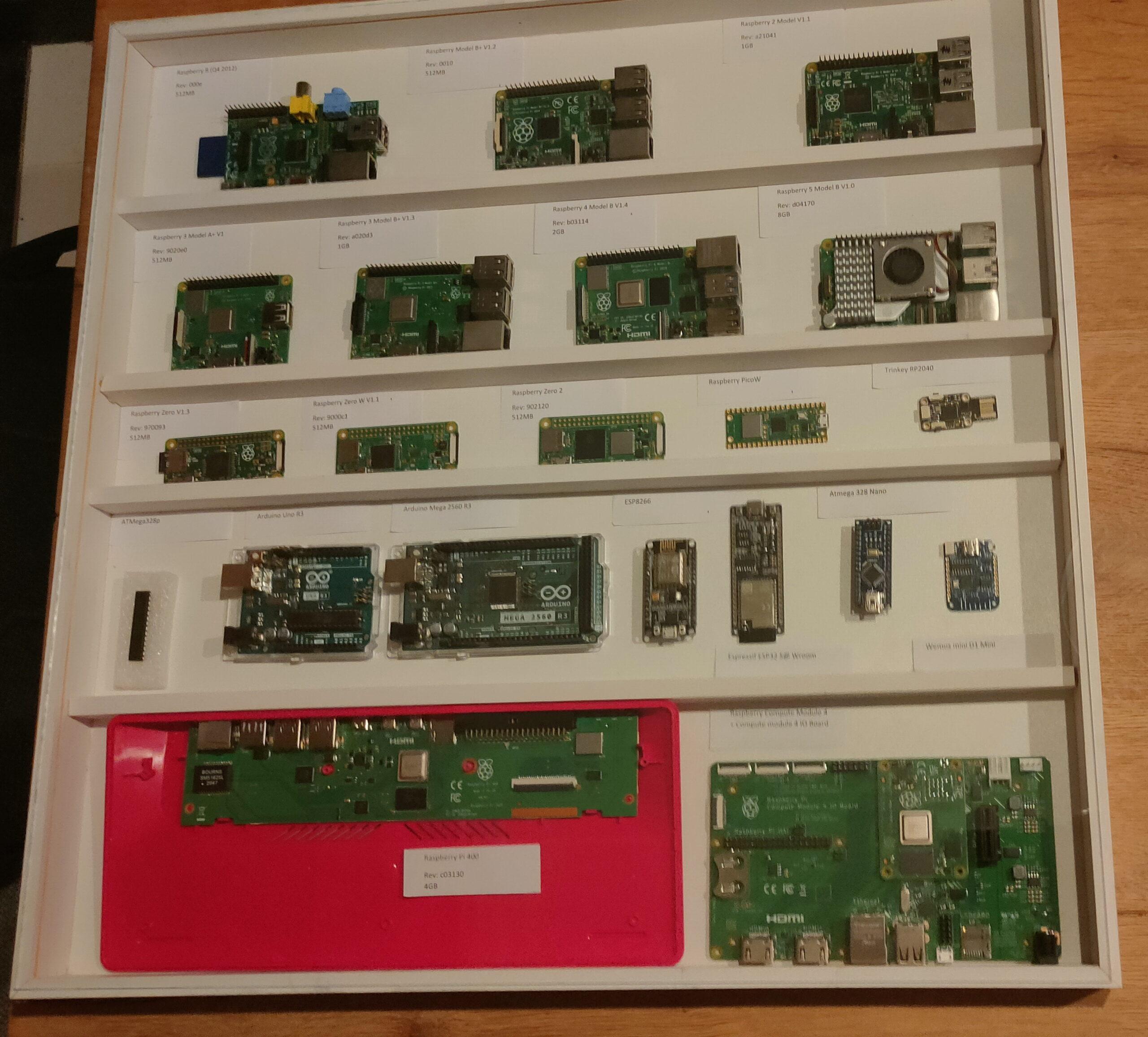
I started a little case for a collection of Raspberry devices.
Over the years, many Raspberries were designed and made. It all started in 2012 I want to have a case with all RP’s i’ve used.
There are many iterations of the RPi, I’m missing a lot now. If you want to help me, send me old/broken raspberries to get the collection complete!
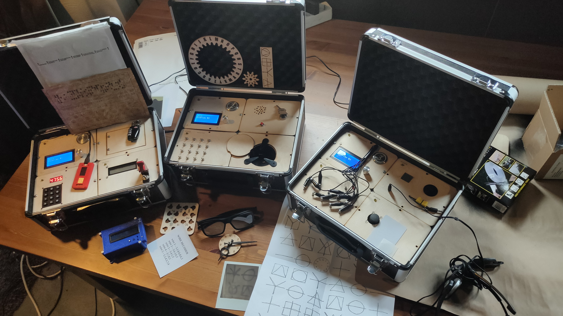
This is the case at the moment
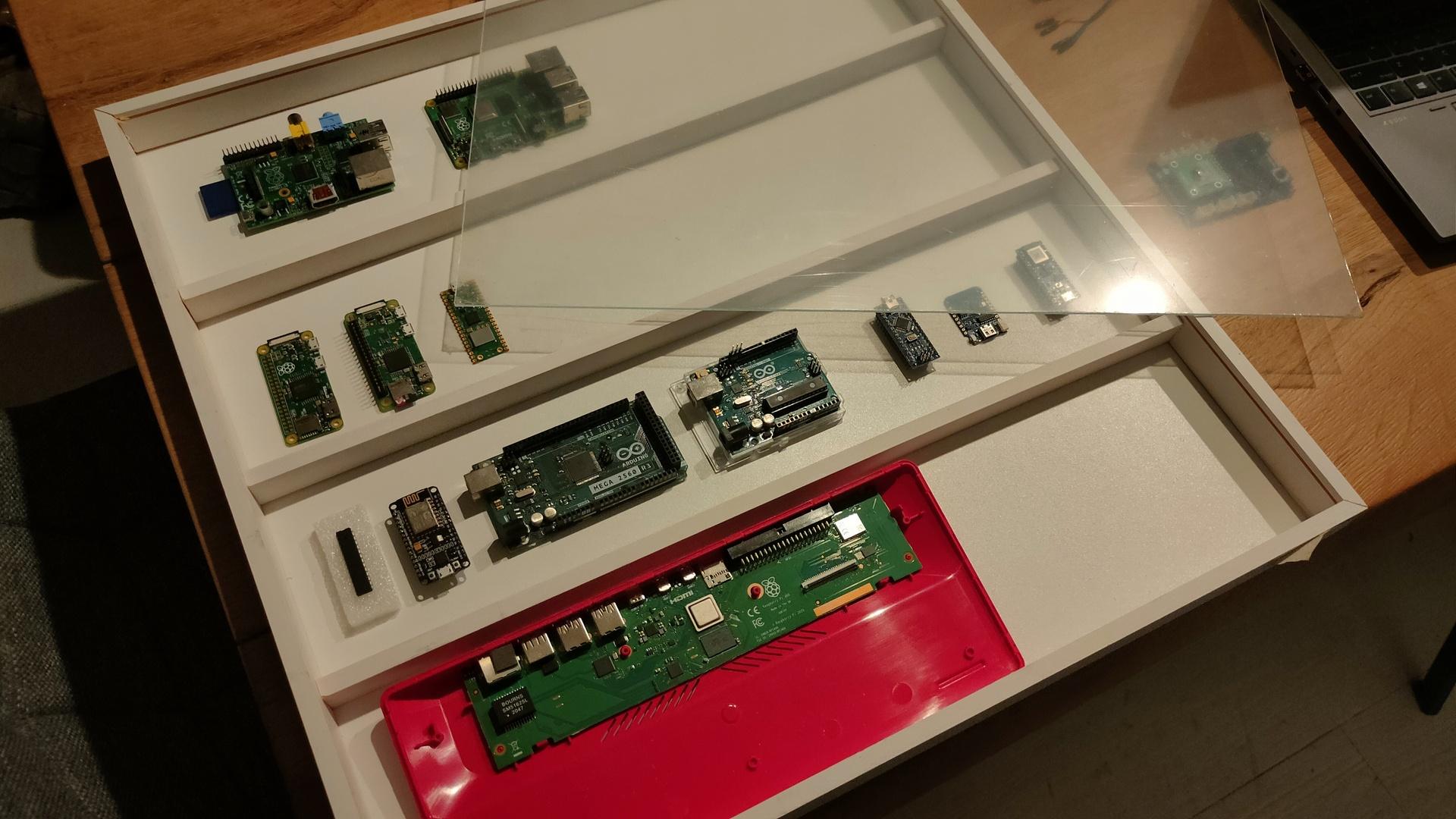
Case with some Raspberries and Arduino’s I found lying around, I’m not going to dismantle projects. Only the RPi 1A, 4B, Zero, Zero W, Pico and RPi 400 are displayed. Plastic sheet as protective layer still on there, should be clear as glass.
The case isn’t glued together yet. I’m not sure how and what to include.
Horizontal wooden bars to place the devices on?
Include a history of Arduino’s for now?
Put little notes in the case with information? Like my SDK-85 case?
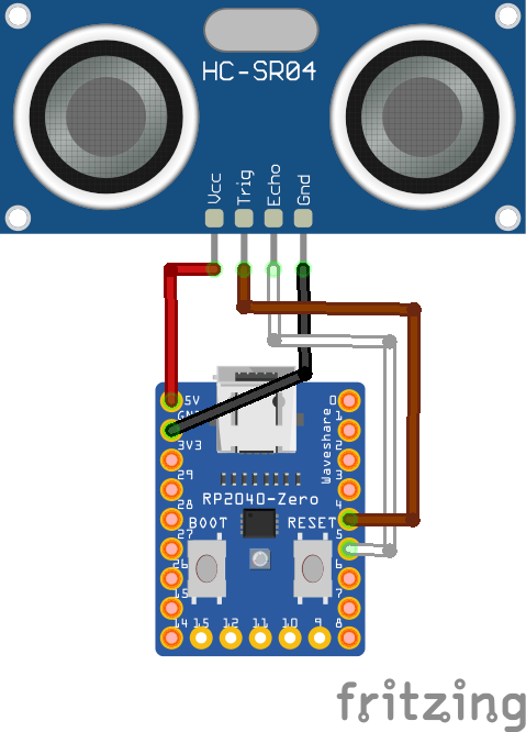
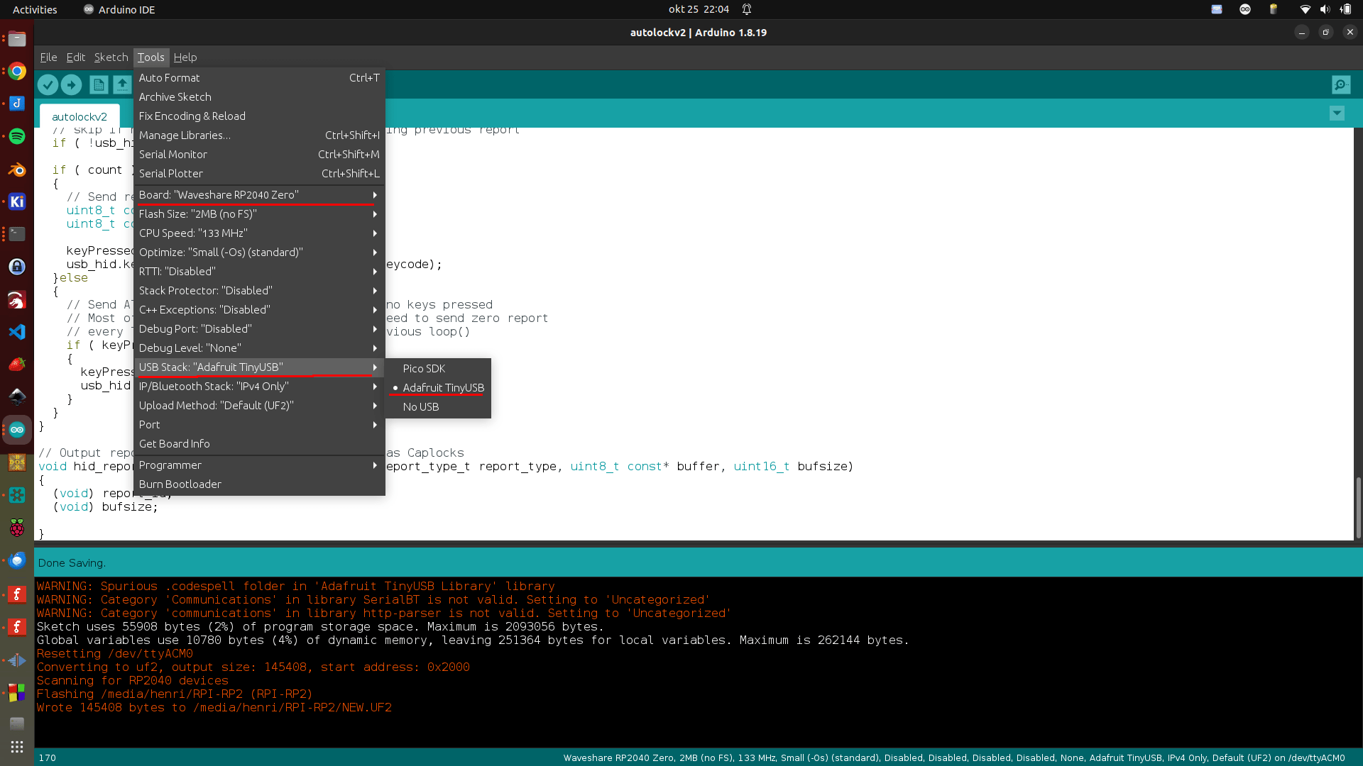
Point the sensor at yourself when behind your computer. When you leave your computer for some seconds, it wil automatically lock your screen. (Windows-L keypress) The RP2040 is configured as HID so it emulates a keyboard. Just connect via an usb-cable to your machine
#include "Adafruit_TinyUSB.h"
// defines pins numbers
const int trigPin = D4;
const int echoPin = D5;
// defines variables
long duration;
int distance;
int maxcounter;
uint8_t const desc_hid_report[] =
{
  TUD_HID_REPORT_DESC_KEYBOARD()
};

// D0-D3 NOT USED AT THE MOMENT, I'VE GOT IDEAS FOR EXTRA FUNCTIONALLITY!

// USB HID object. For ESP32 these values cannot be changed after this declaration
// desc report, desc len, protocol, interval, use out endpoint
Adafruit_USBD_HID usb_hid(desc_hid_report, sizeof(desc_hid_report), HID_ITF_PROTOCOL_KEYBOARD, 2, false);

//------------- Input Pins -------------//
// Array of pins and its keycode.
  uint8_t pins[] = { D0, D1, D2, D3 };


// number of pins
uint8_t pincount = sizeof(pins)/sizeof(pins[0]);

// For keycode definition check out https://github.com/hathach/tinyusb/blob/master/src/class/hid/hid.h
uint8_t hidcode[] = { HID_KEY_0, HID_KEY_1, HID_KEY_2, HID_KEY_3 , HID_KEY_4, HID_KEY_5 };

#if defined(ARDUINO_SAMD_CIRCUITPLAYGROUND_EXPRESS) || defined(ARDUINO_NRF52840_CIRCUITPLAY) || defined(ARDUINO_FUNHOUSE_ESP32S2)
  bool activeState = true;
#else
  bool activeState = false;
#endif

void setup()
{
  // Setting pins for Ultrasonic Sensor HC-SR04
  pinMode(trigPin, OUTPUT); // Sets the trigPin as an Output
  pinMode(echoPin, INPUT); // Sets the echoPin as an Input

#if defined(ARDUINO_ARCH_MBED) && defined(ARDUINO_ARCH_RP2040)
  // Manual begin() is required on core without built-in support for TinyUSB such as mbed rp2040
  TinyUSB_Device_Init(0);
#endif

  // Set up output report (on control endpoint) for Capslock indicator
  // Not used .. yet
  usb_hid.setReportCallback(NULL, hid_report_callback);

  usb_hid.begin();

  // overwrite input pin with PIN_BUTTONx
  // NOT USED
#ifdef PIN_BUTTON1
  pins[0] = PIN_BUTTON1;
#endif

#ifdef PIN_BUTTON2
  pins[1] = PIN_BUTTON2;
#endif

#ifdef PIN_BUTTON3
  pins[2] = PIN_BUTTON3;
#endif

#ifdef PIN_BUTTON4
  pins[3] = PIN_BUTTON4;
#endif

  // Set up pin as input
  for (uint8_t i=0; i<pincount; i++)
  {
    pinMode(pins[i], activeState ? INPUT_PULLDOWN : INPUT_PULLUP);
  }

  // wait until device mounted
  while( !TinyUSBDevice.mounted() ) delay(1);

maxcounter =0;
}

void loop()
{

  // Clears the trigPin
  digitalWrite(trigPin, LOW);
  delayMicroseconds(2);
  // Sets the trigPin on HIGH state for 10 micro seconds
  digitalWrite(trigPin, HIGH);
  delayMicroseconds(10);
  digitalWrite(trigPin, LOW);
  // Reads the echoPin, returns the sound wave travel time in microseconds
  duration = pulseIn(echoPin, HIGH);
  // Calculating the distance
  distance = duration * 0.034 / 2;
  // Prints the distance on the Serial Monitor - DEBUG
  //Serial.print("Distance: ");
  //Serial.println(distance);

  // Below will wait for more than 100 measurements with a distance of 100
  // Then it will send a WINDOWS-L (lock) keyboard combination
  if (distance > 100)
  {
    maxcounter +=1;
  }
  else
  {
    maxcounter = 0;
  }
  if (maxcounter > 100 && maxcounter < 150)
  {
    maxcounter = 200;
       // Send report if there is key pressed
    uint8_t const report_id = 0;


    uint8_t  modifier = KEYBOARD_MODIFIER_LEFTGUI;
          uint8_t keycode[6] = { 0 };
      keycode[0] = HID_KEY_L;


    usb_hid.keyboardReport(report_id, modifier, keycode);
    delay(10);
    // Un-press keys :)
    usb_hid.keyboardRelease(0);

  }


  // poll gpio once each 2 ms
  delay(20);

  // used to avoid send multiple consecutive zero report for keyboard
  static bool keyPressedPreviously = false;

  uint8_t count=0;
  uint8_t keycode[6] = { 0 };

  // scan normal key and send report
  for(uint8_t i=0; i < pincount; i++)
  {
    if ( activeState == digitalRead(pins[i]) )
    {
      // if pin is active (low), add its hid code to key report
      keycode[count++] = hidcode[i];

      // 6 is max keycode per report
      if (count == 6) break;
    }
  }

  if ( TinyUSBDevice.suspended() && count )
  {
    // Wake up host if we are in suspend mode
    // and REMOTE_WAKEUP feature is enabled by host
    TinyUSBDevice.remoteWakeup();
  }

  // skip if hid is not ready e.g still transferring previous report
  if ( !usb_hid.ready() ) return;

  if ( count )
  {
    // Send report if there is key pressed
    uint8_t const report_id = 0;
    uint8_t const modifier = 0;

    keyPressedPreviously = true;
    usb_hid.keyboardReport(report_id, modifier, keycode);
  }else
  {
    // Send All-zero report to indicate there is no keys pressed
    // Most of the time, it is, though we don't need to send zero report
    // every loop(), only a key is pressed in previous loop()
    if ( keyPressedPreviously )
    {
      keyPressedPreviously = false;
      usb_hid.keyboardRelease(0);
    }
  }
}

// Output report callback for LED indicator such as Caplocks
void hid_report_callback(uint8_t report_id, hid_report_type_t report_type, uint8_t const* buffer, uint16_t bufsize)
{
  (void) report_id;
  (void) bufsize;

}
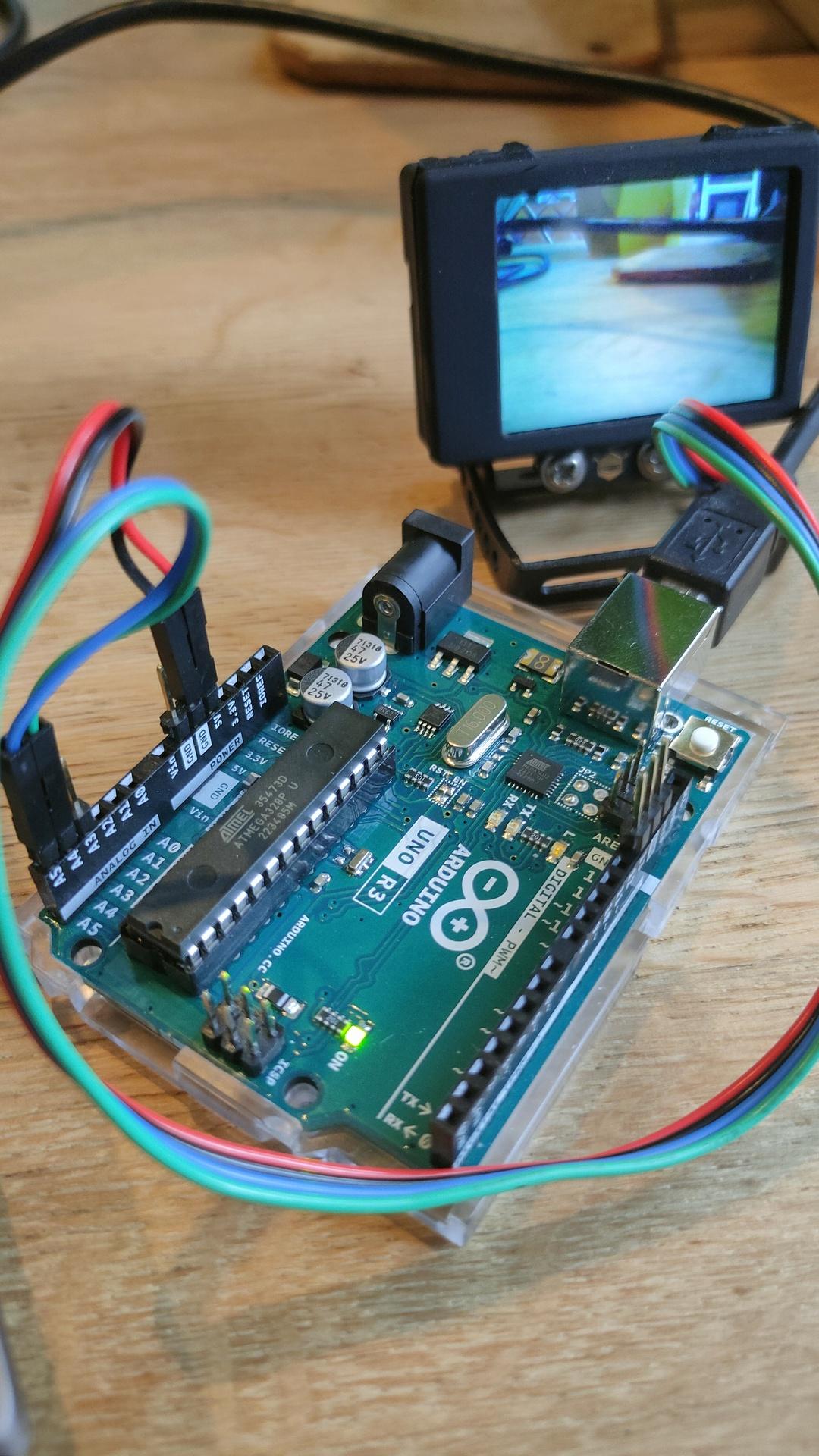
The HuskyLens is an easy-to-use AI machine vision sensor. It is equipped with multiple functions such as:
Face recognition
Object tracking
Object recognition
Line trace
Color recognition
Tag recognition (QR code).
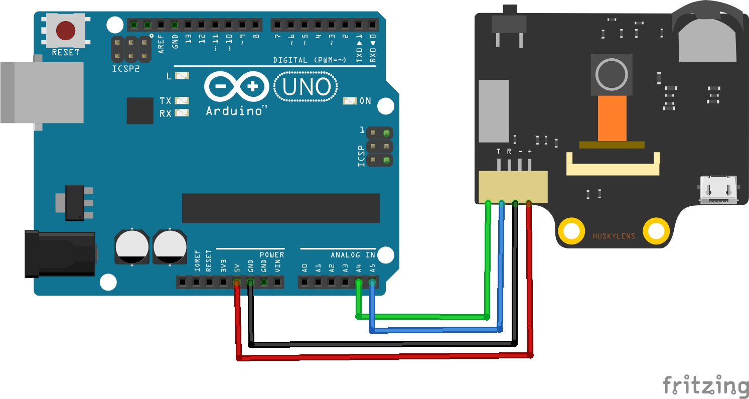
Via the UART / I2C port you can among others: boards connect:
Arduino
micro:bit
Raspberry Pi
Steps to take: Press Face detection, when a cross in a square is displayed, press the button on your HuskyLens
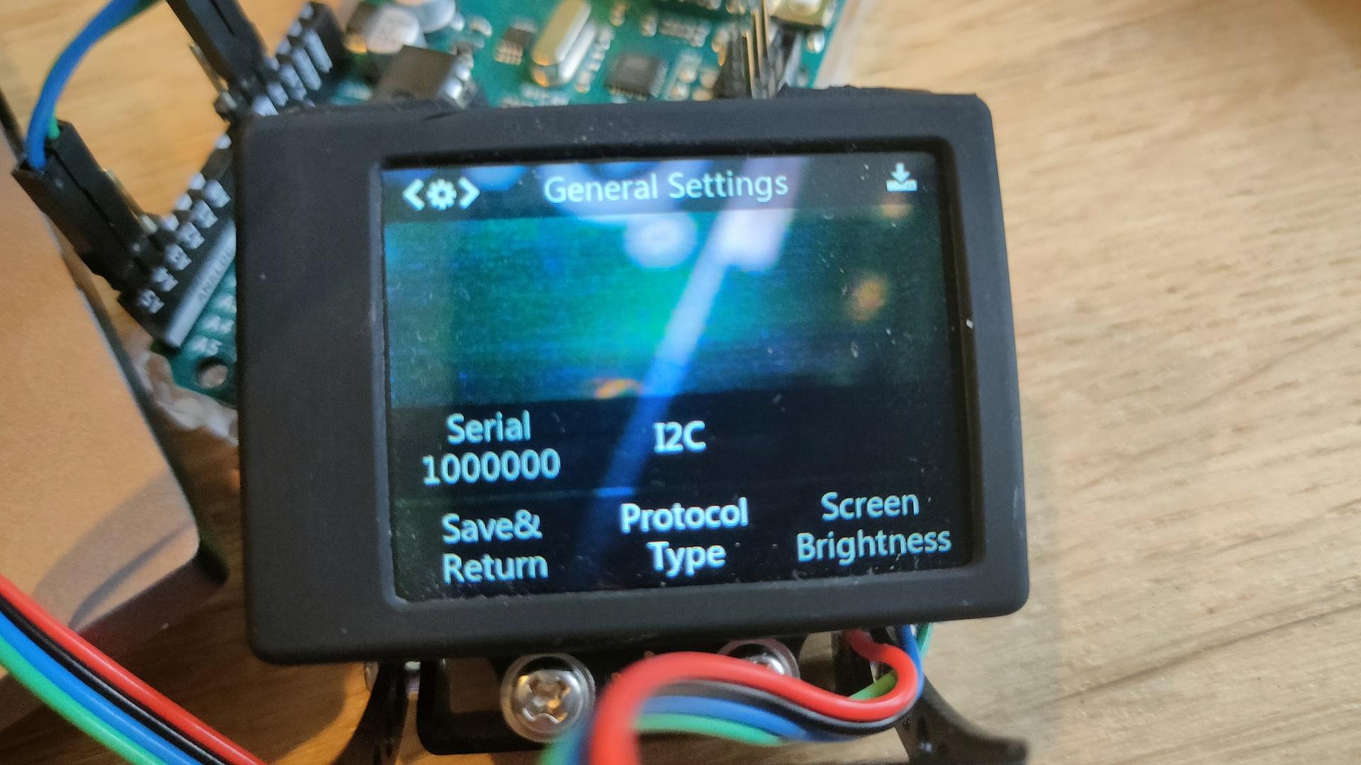
Set your husky protocol to I2C in the settings.
Minimal Code needed
/***************************************************
 HUSKYLENS An Easy-to-use AI Machine Vision Sensor
 <https://www.dfrobot.com/product-1922.html>
****************************************************/

#include "HUSKYLENS.h"

HUSKYLENS huskylens;
//HUSKYLENS green line >> SDA; blue line >> SCL
int ID0 = 0; //not learned results. Grey result on HUSKYLENS screen
int ID1 = 1; //first learned results. colored result on HUSKYLENS screen
int ID2 = 2; //second learned results. colored result on HUSKYLENS screen
// and so on.....

int arjprevious = 0;
void printResult(HUSKYLENSResult result);
void setup() {
    Serial.begin(115200);
    Wire.begin();
    while (!huskylens.begin(Wire))
    {
        Serial.println(F("Begin failed!"));
        Serial.println(F("1.Please recheck the \"Protocol Type\" in HUSKYLENS (General Settings>>Protocol Type>>I2C)"));
        Serial.println(F("2.Please recheck the connection."));
        delay(100);
    }

     huskylens.writeAlgorithm(ALGORITHM_FACE_RECOGNITION);
}

void loop() {
   if (huskylens.requestLearned())          //request blocks and arrows tangged ID != 0 from HUSKYLENS
   if (huskylens.requestBlocksLearned())    //request blocks tangged ID != ID0 from HUSKYLENS

    {
        for (int i = 0; i < huskylens.countArrows(ID0); i++)
        {
            HUSKYLENSResult result = huskylens.getArrow(ID0, i);
        }
        int arj = huskylens.count(ID1);
        if ( arj != arjprevious )
        {
        if ( arj == 1 )
            {
            Serial.println("Learned face detected");
            }
            else
            {
            Serial.println("Learned face not detected");
            }
            arjprevious = arj;
        }
    }
    else
    {
        Serial.println("Fail to request objects from Huskylens!");
    }
}
Learned face detected ID1
Learned face not detected
Learned face detected ID1
Learned face not detected
Learned face detected ID1
Learned face not detected
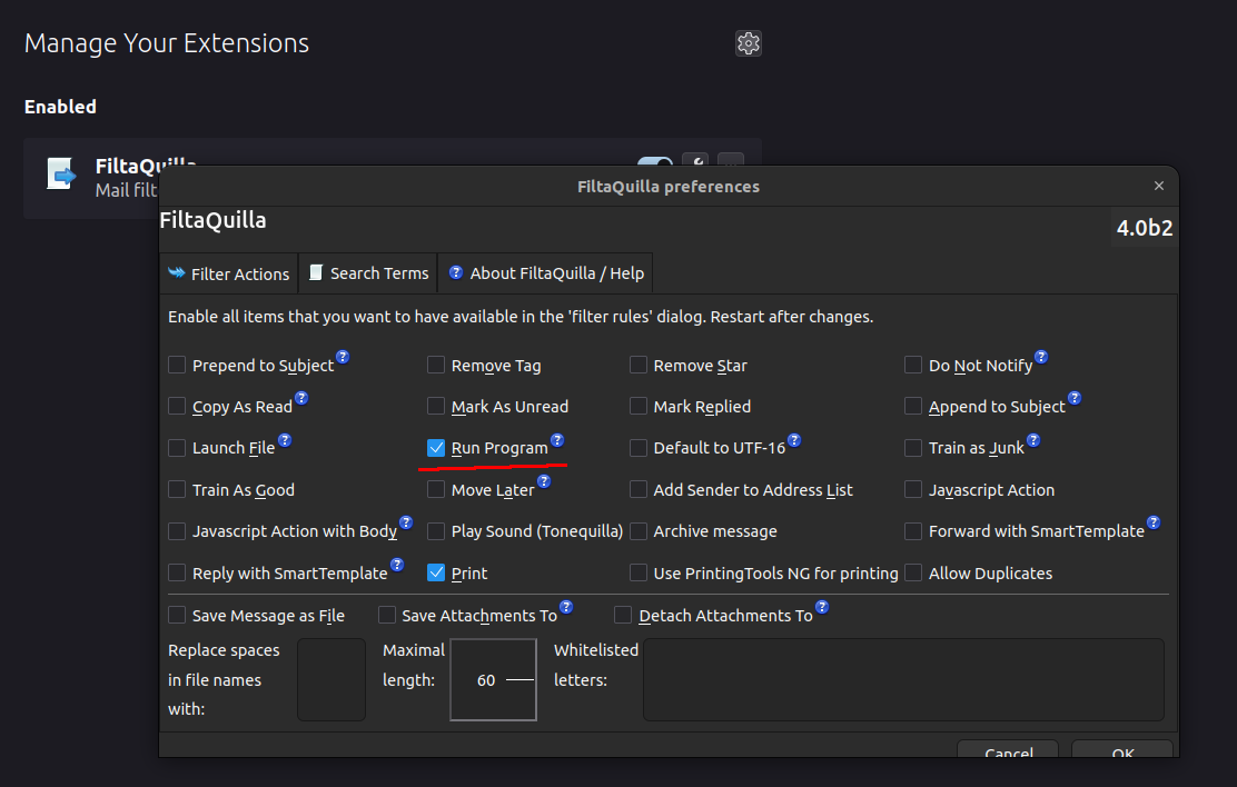
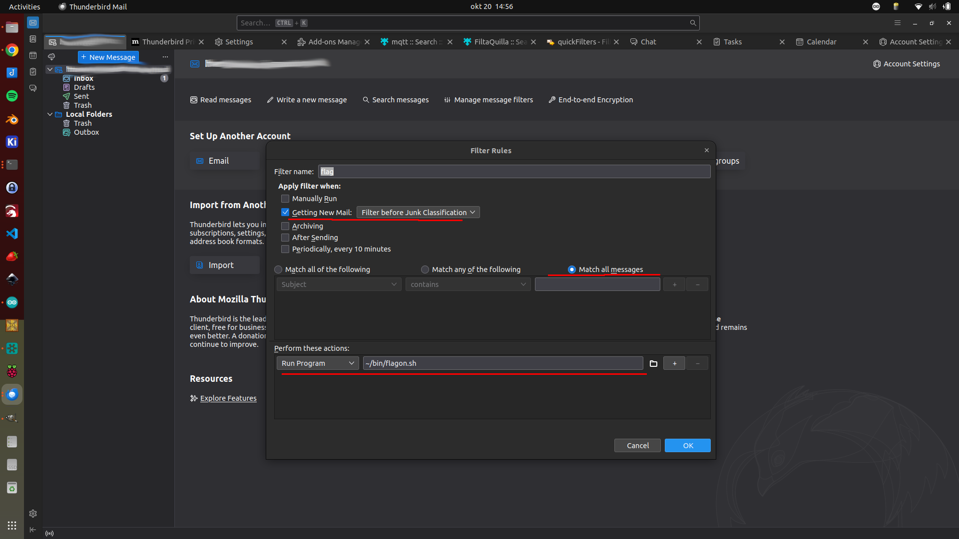
Now i’ve changed the notification flag for Email using Thunderbird. Just connect the wemos to a USB on your computer, no mqtt/wifi needed. (On the road solution)
Steps:
Install FiltaQuilla Add-on in thunderbird select run program in config.
Next create a filter
Create two bash files (i’ve got mine in ~/bin/ ) Change ttyUSB0 if needed
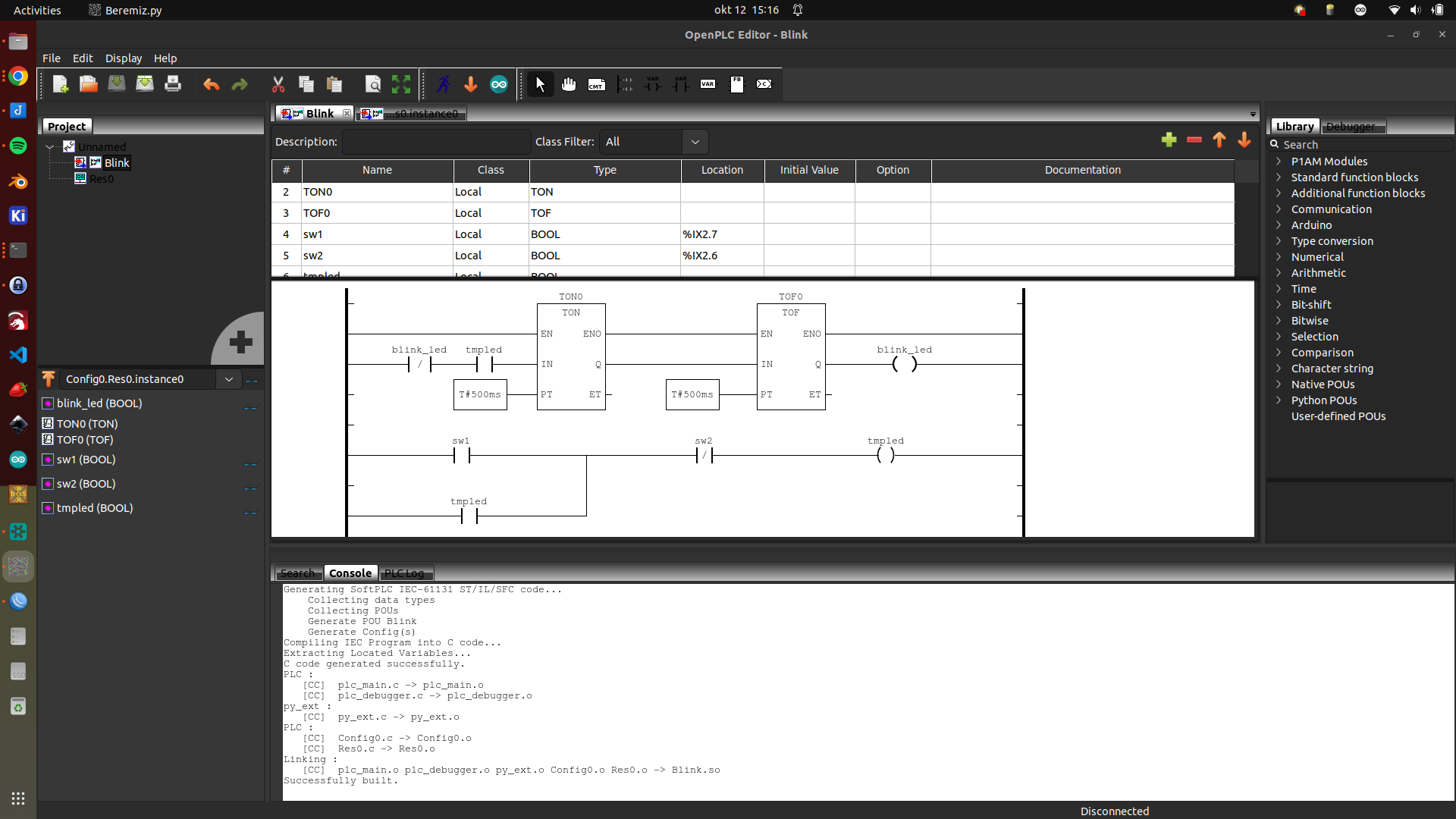
It’s a long time i’ve made a PLC ladder, but lets see how and what this integration brings me.
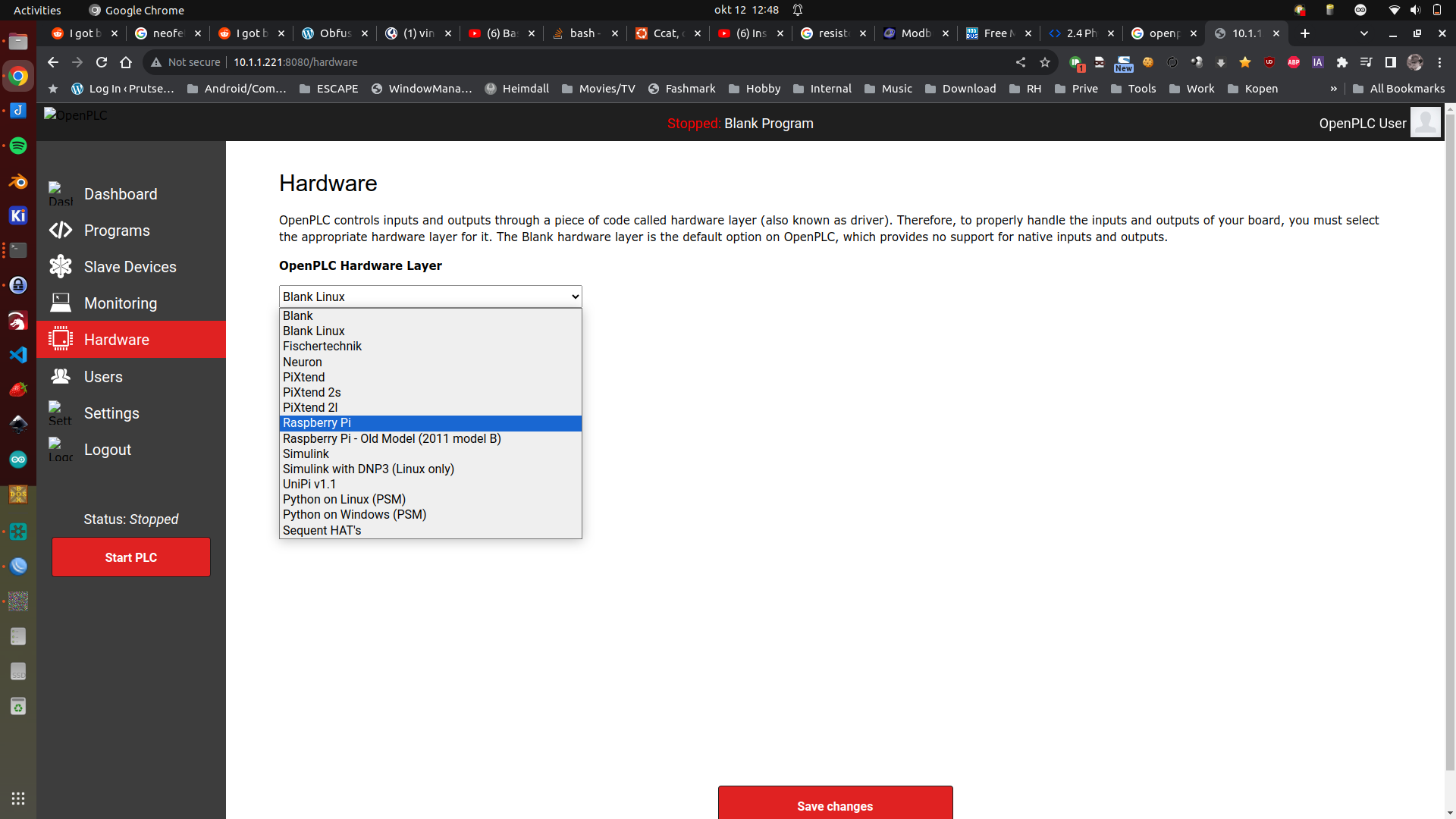
OpenPLC interface on a Raspberry, I could not start a program on RPI 5! But it compiled correctly. See below rpi3
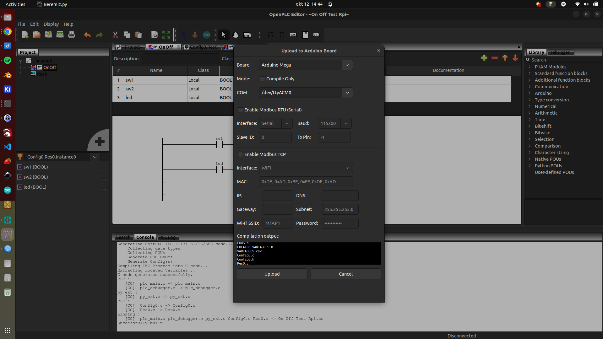
OpenPLC editor with timer ladders for Arduino
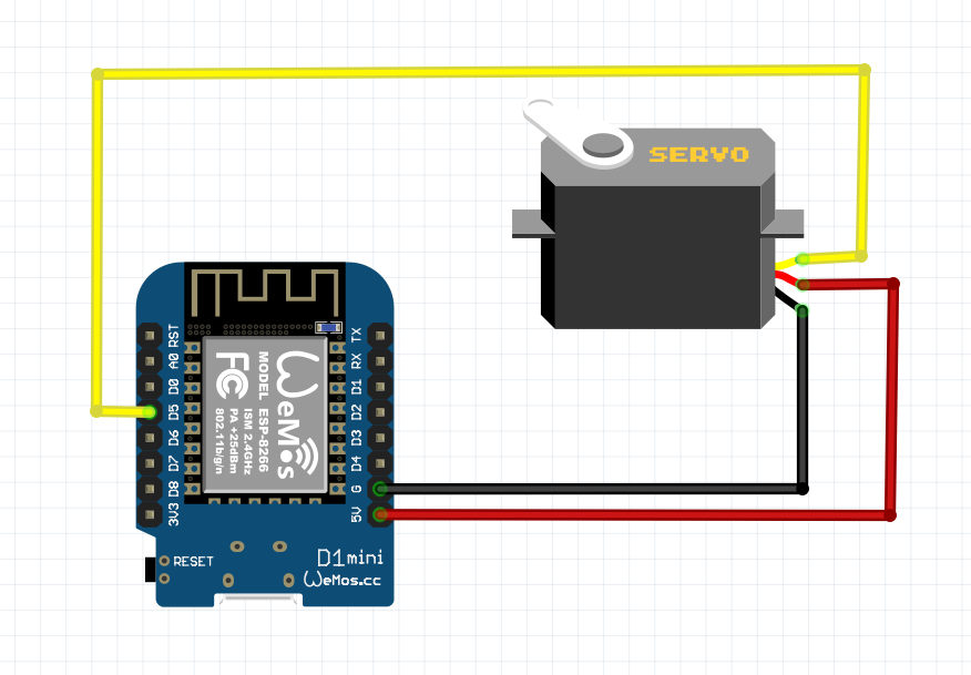
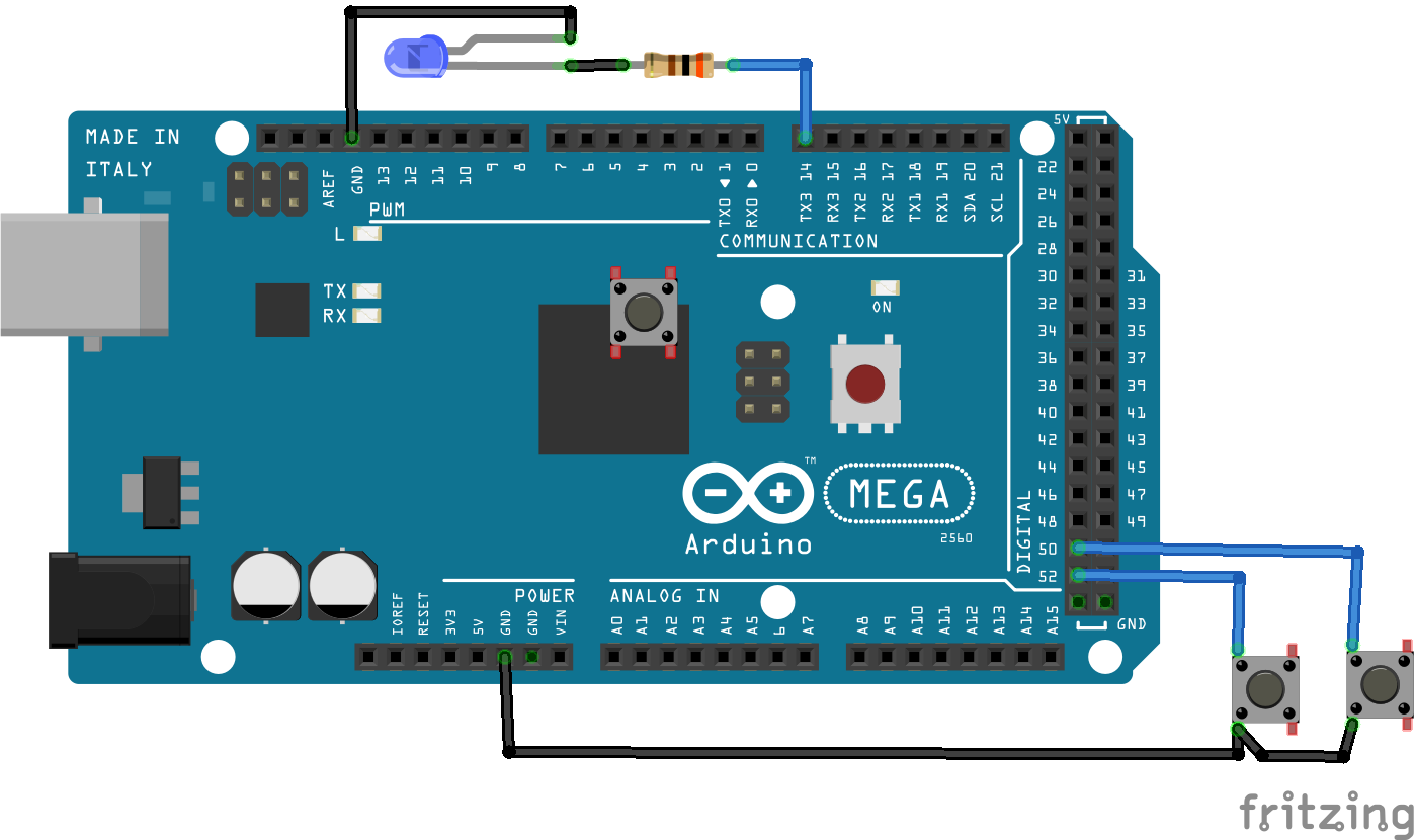
Schematic with a led and two buttons (and one floating in the middel, which i forgot to remove)
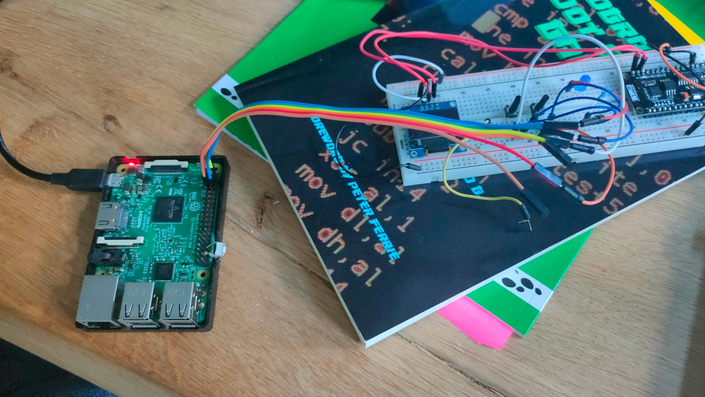
Working example ( wemos and display are from another project those are not connected )
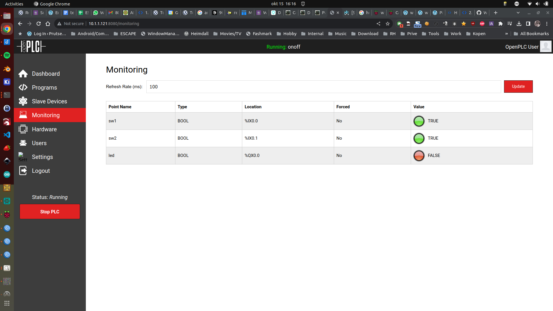
UPDATE 20231015 – Raspberry 3 with OpenPLC
GND to leds and buttons GPIO2 (pin 3) to a button GPIO3 (pin 5) to another button GPIO14 (pin 8) to the led
Now OpenPLC works correct (RPI3)
https://github.com/thiagoralves/OpenPLC_v3.git
cd OpenPLC_v3
./install.sh rpi

## Warning .. takes a really long time

Wiringpi is deprecated
But can be installed using the last git repo

git clone https://github.com/WiringPi/WiringPi.git
cd WiringPi
./build
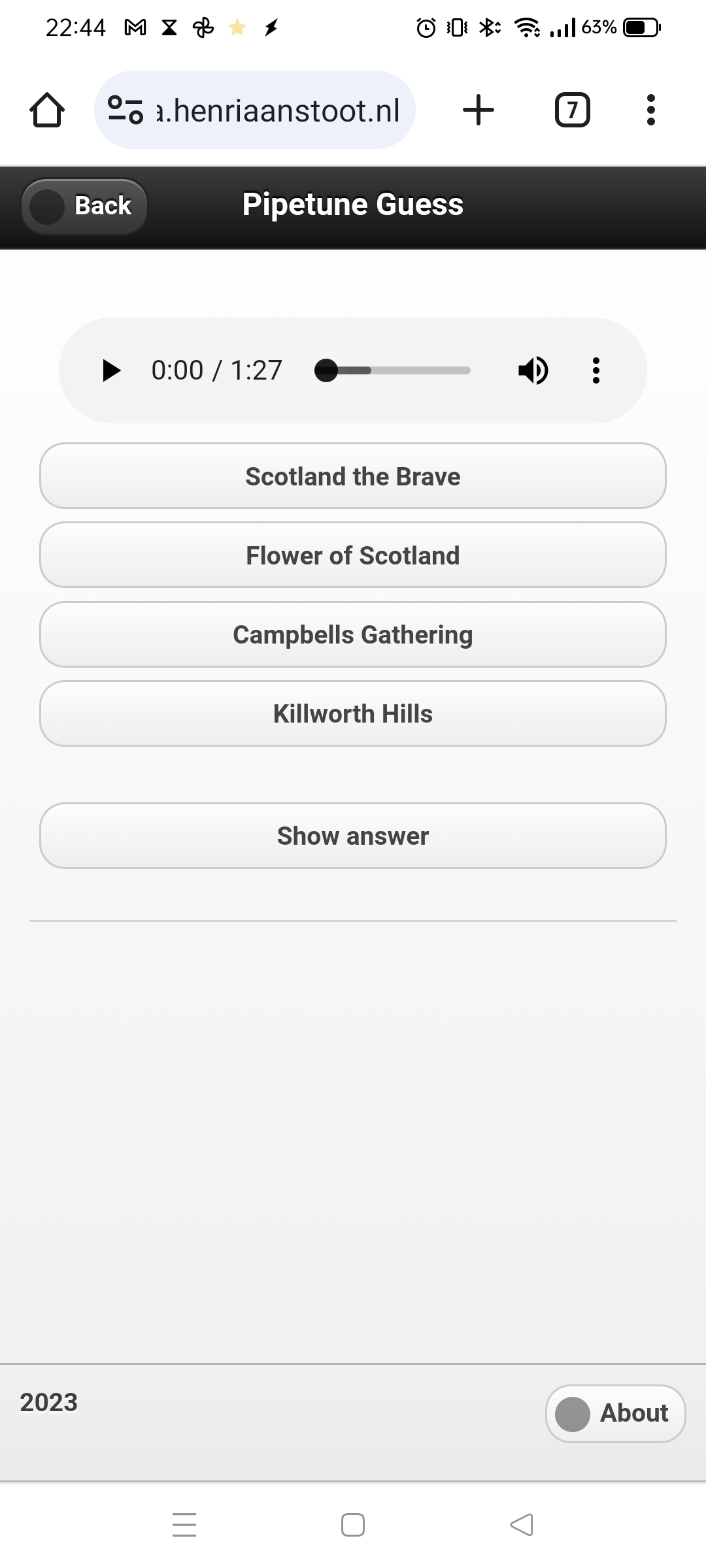
While watching a online python course, I was writing the code for a music guessing game (Highland Bagpipe Tunes) The core is working, now it’s a matter of filling this “pruts” with tunes.
Switching between python, php, bash and C is a nightmare 🙂
A screenshot of work in progress
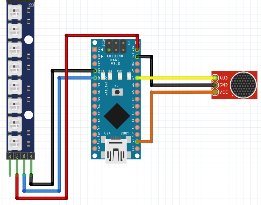
Then the postman came .. with goodies. I needed the MAX9814 analog microphone with amplifier, all of my other sensors were not up to the task.
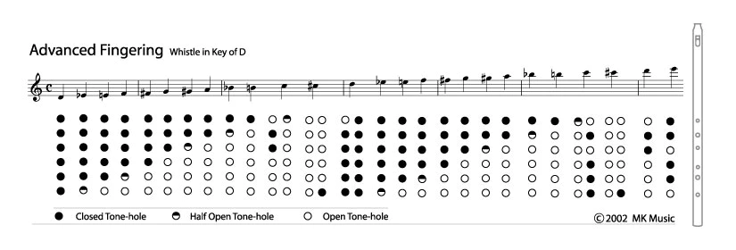
So I switched to this WIP with the MAX9814. I want to make a little gadget using an Arduino and 9 leds, which uses FFT to blink which note I am playing on my Highland Pipes.
So detecting is working, now I have to attach a bunch of leds.
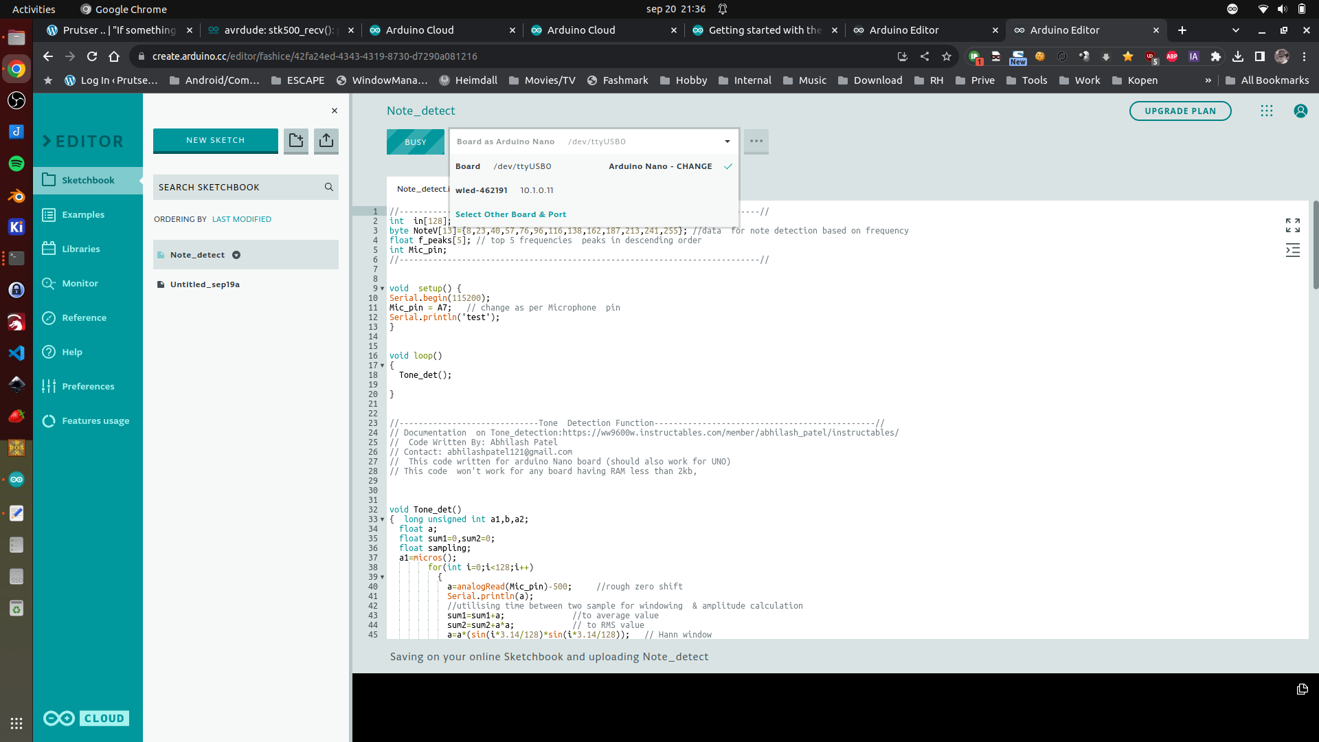
First test using Arduino Cloud (I still prefer PlatformIO) But this is better than the old IDE. (Note, you have to install an agent to connect your browser to a board)
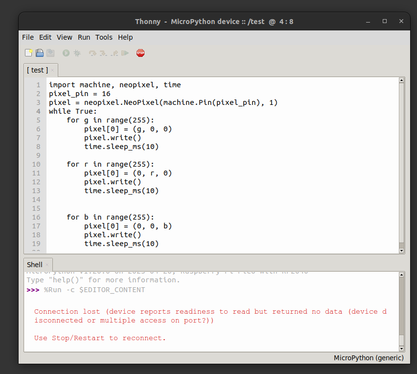
Next thing I did today: Getting my waveshare RP-2040 Zero working with micropython.
Great the little NeoPixel Led on the board.
Steps to get this working:
Install Thonny
Connect the rp2040 via USB with the boot button pressed
place RPI_pico.xxxx.uf2 on the mounted usb disk, it will reboot
Run Thonny connect and run a test program
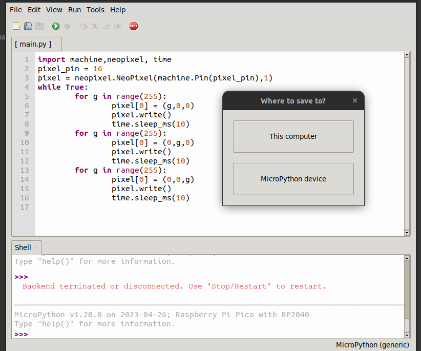
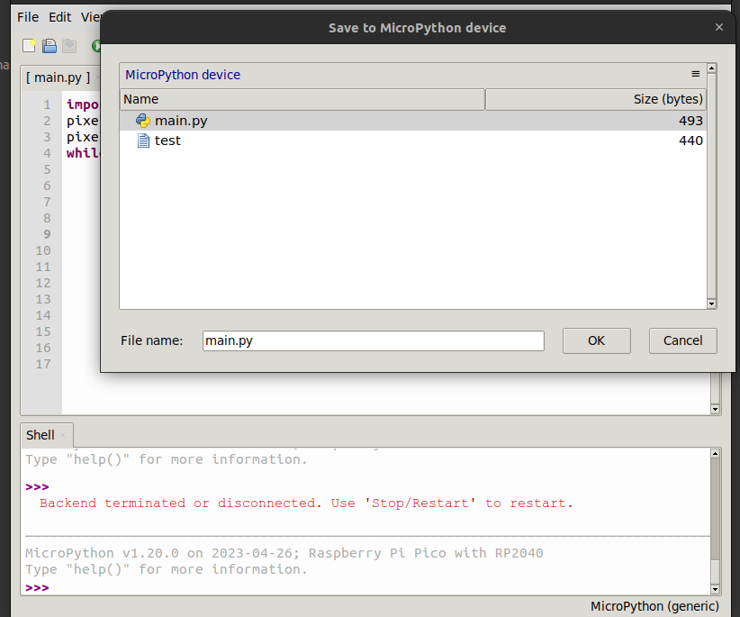
Want to run program @boot ? save -> to device, and call main.py
I’ve got a Wifi outside of my network for guest and emergency. ( 2 SSIDs)
Then a main Wifi router in my livingroom, one in my workshop/studio and one in the Attic (Electronics Lab)
So three main Wifi AccessPoints. These all have the same SSID’s but on different frequencies. That way i’ve got roaming in and outside my house. Also some virtual accesspoints are configured. I’ve got a main, folkband, IOT, guest-inside all on 2.4Ghz and 5Ghz.
I watched a lot of YT presentations about Mikrotik Wifi.
So I ended up with DFS safe channels 20Mhz for 2.4 and 20/40Mhz Ce for 5Ghz. (subchannels for each after some frequency scanning) (2.4 does a failback to 20Mhz whenever there is even one client detected which connects only on this band. Such as some old IOT stuff) 2.4 in only 1,6 and 11 no overlap, each on another device. 300Mbps is sufficient for my wifi 🙂
I’ve got accesslists in place and i’m going to read into kicking a client when the signal strenght is below -50dB
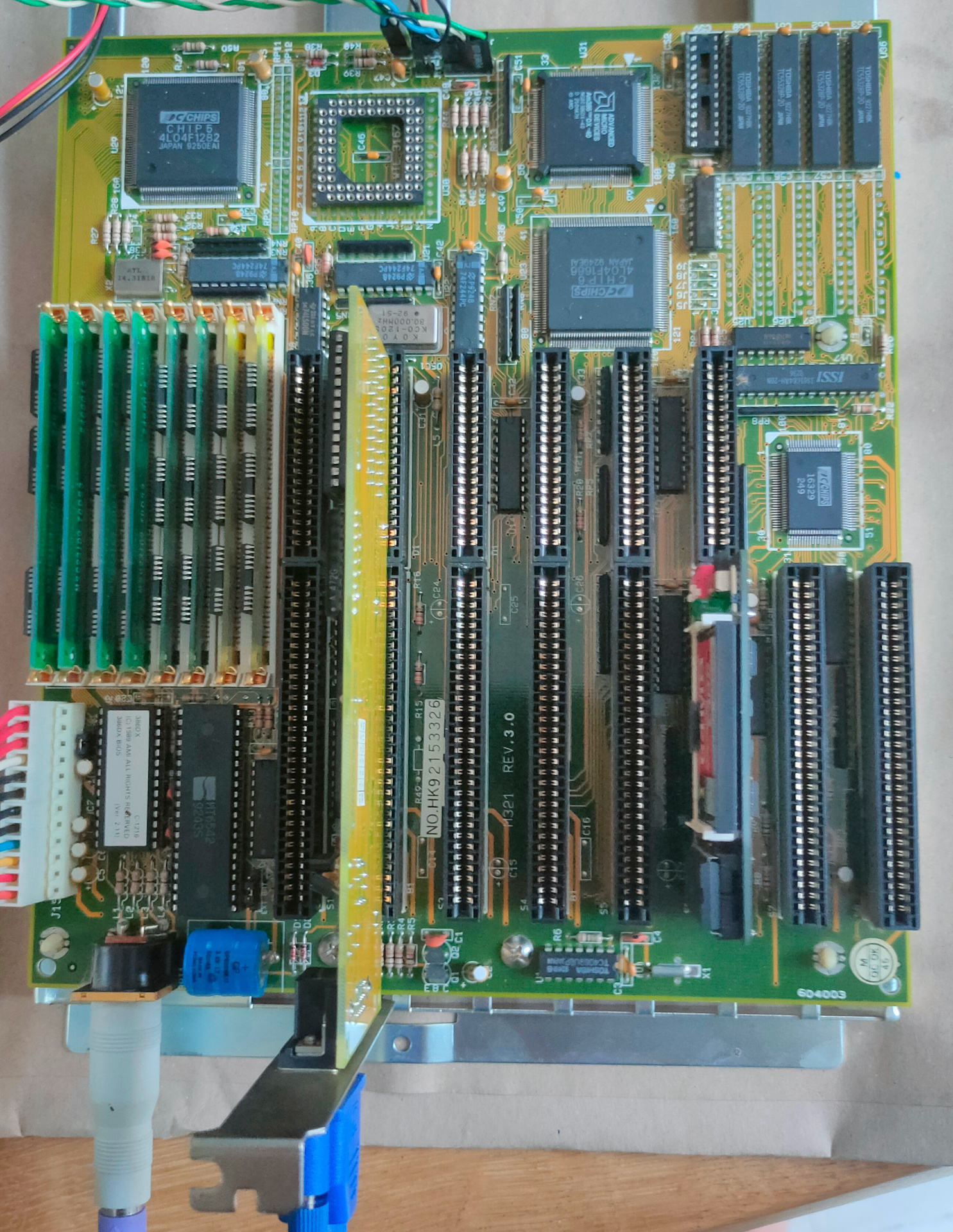
80386 (DX) Computer
Besides my 8088 and 8086 machines I needed a machine which could run our old demo’s. So I bought a new toy.
It has 8Mb Ram and runs at 40Mhz.
I’ve noticed that many of my VGA register manipulation code, can’t be run on a modern VGA monitor, I need to use a CRT for that .. Another thing to buy
Needed to fix arduino code, due to the TFT_eSPI library issues. And I’ve got a S3 with another resolution, but that was an easy fix. Then needed to reinstall nodejs with another version. Had to modify the code because the tcp server would not start. Weird errors logging, but in the end fixed … very cool
I probably end up designing a 3D printed case that looks like a monitor or tv.