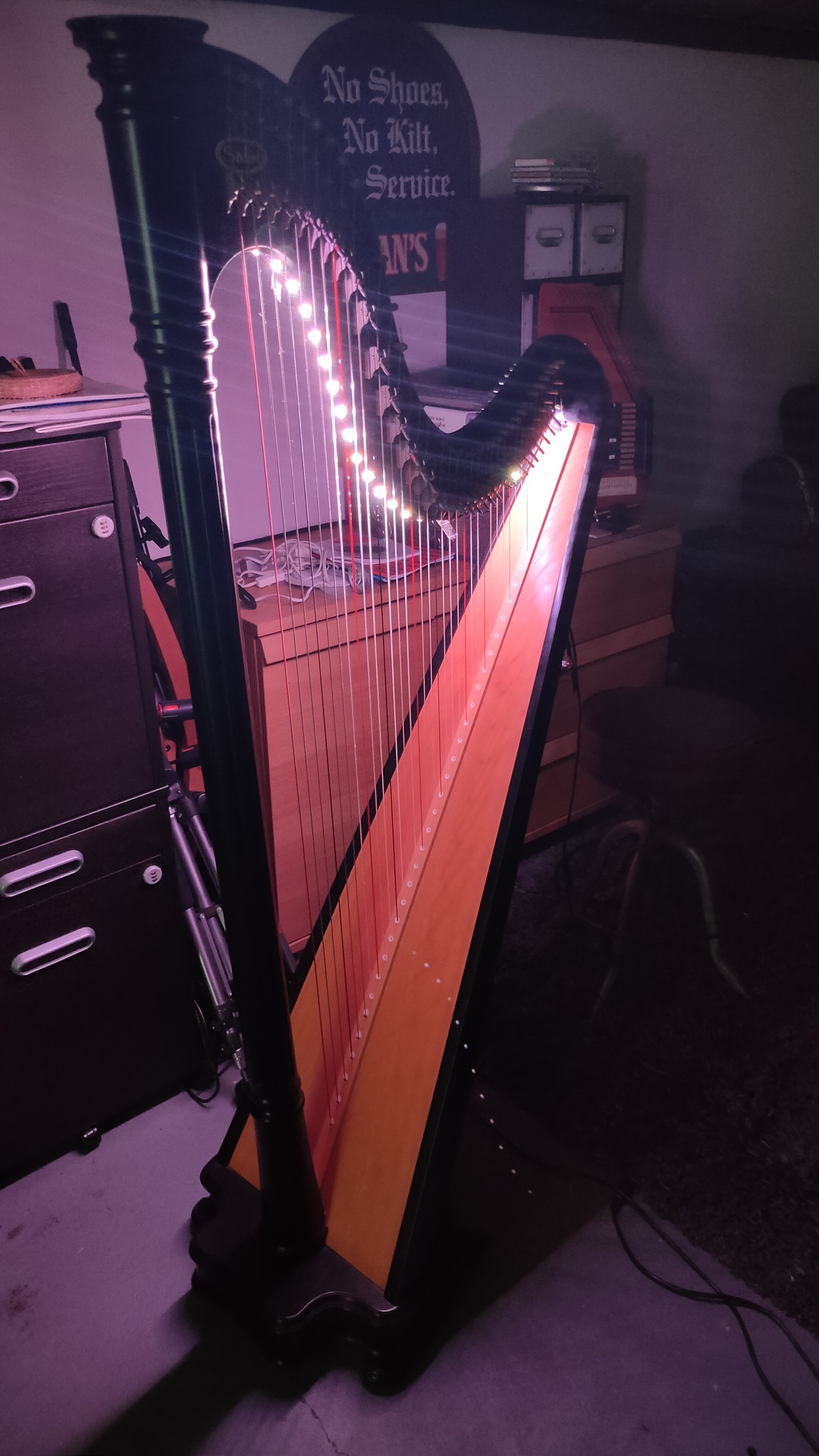
A ledstrip on a Harp, now I can see the strings at night!
Woohoo .. ( Little harp in the background (autoharp))
Well .. its a pity that the distance of the leds is NOT the same as the strings distance.
I could light up the string to be played, or even cooler … When using FFT code (Fast Fourier Transform), I could light up the string being played! I’m probably going to try to implement this at a later time.
PlatformIO tested ( install StackArray.h in lib/StackArray/StackArray.h )
Reset button and dipswitches for below options
Visited pathmode ( dip switch 1)
Preview maze generation ( dip switch 3)
Hard mode – starts at first position when hitting a wall ( dip 2 )
Longest path mode (longest stackarray before stack.pop (dip 4 )
Prints serial info, like a drawn maze
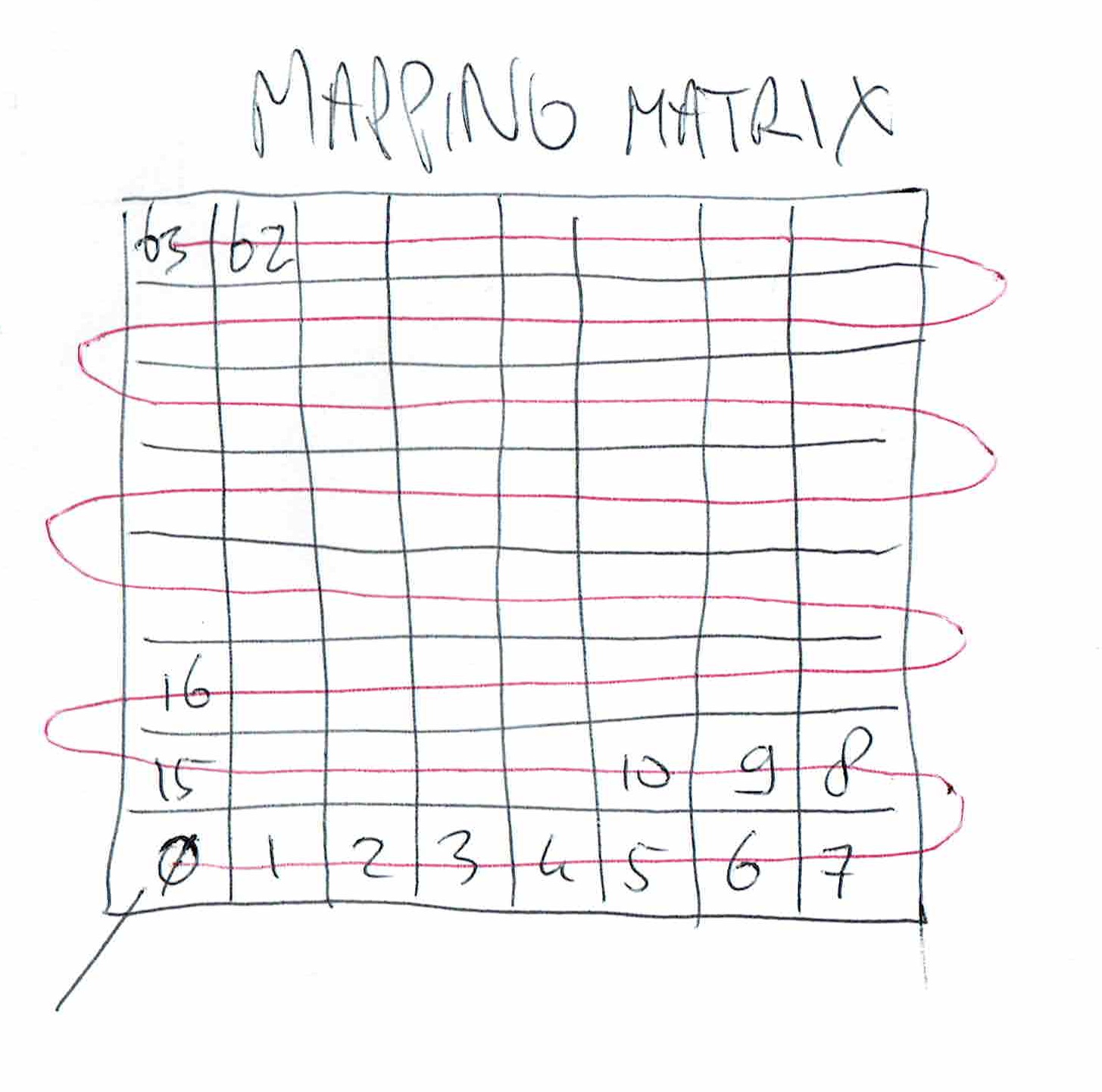
Pixel remapping for other displays ( Below mapping i had to use, see source sketch )
How is the maze generated?
It is generated using recursive backtracking:
Start at 0,0 mark visited, select a random direction from unvisited neighbours, push current on the stack, goto new location, and mark this visited. Repeat until no possible directions. pop from the stack a previous location, another direction possible? Take that path and repeat. Repeat popping from stack, until stack empty .. now all cells are visited
Make an initial cell the current cell
   mark it as visited
While there are unvisited cells
   If the current cell has any neighbours
   which have not been visited
         Choose randomly one of the unvisited neighbours
                Push the current cell to the stack
                Mark wall hole
                Make the chosen cell the current cell
                mark it as visited
        Else if stack is not empty
                Pop a cell from the stack
                Make it the current cell
This is my implementation of backtracking
The displaymatrix function is a implementation of different led mappings
Still have to decide where to place endpoint … At 8,8 or at first stack pop? Maybe both?
Code
#include <WEMOS_Matrix_LED.h>
#include <StackArray.h>

int directions[4]{};
int notalldone = 1;
int tmpx=0;
int tmpy=0;
int x = 1;
int y = 1;
MLED mled(5); //set intensity=5

int maze[8][8] = {
  };

int displaymatrix[8][8] = {
{ 0,1,2,3,4,5,6,7 },
{ 8,9,10,11,12,13,14,15 },
{16,17,18,19,20,21,22,23},
{24,25,26,27,28,29,30,31},
{32,33,34,35,36,37,38,39},
{40,41,42,43,44,45,46,47},
{48,49,50,51,52,53,54,55},
{56,57,58,59,60,61,62,63}
};

int visitmatrix[10][10] = {
  1,1,1,1,1,1,1,1,1,1,
  1,0,0,0,0,0,0,0,0,1,
  1,0,0,0,0,0,0,0,0,1,
  1,0,0,0,0,0,0,0,0,1,
  1,0,0,0,0,0,0,0,0,1,
  1,0,0,0,0,0,0,0,0,1,
  1,0,0,0,0,0,0,0,0,1,
  1,0,0,0,0,0,0,0,0,1,
  1,0,0,0,0,0,0,0,0,1,
  1,1,1,1,1,1,1,1,1,1
  };

void setup() {
    Serial.begin(115200);
    randomSeed(analogRead(0));
    mazegen();
    drawmaze();
}

void mazegen(){
  visitmatrix[x][y]=1;
  StackArray <int> rowStack;
  StackArray <int> colStack;
        rowStack.push(x);
        colStack.push(y);
  while(notalldone == 1){
     visitmatrix[x][y]=1;
        while(!rowStack.isEmpty()) {
        int count=0;
        //up
        if ( visitmatrix[x-1][y] == 0 ){
          directions[count]=1;
          count++;
        }
        //right
        if ( visitmatrix[x][y+1] == 0 ){
          directions[count]=2;
          count++;
        }
        //down
        if ( visitmatrix[x+1][y] == 0 ){
          directions[count]=4;
          count++;
        }
        //left
        if ( visitmatrix[x][y-1] == 0 ){
          directions[count]=8;
          count++;
        }
        // no dir found
        if (count == 0 ) {

          mled.dot(x-1,y-1);
          mled.display();
          x = rowStack.pop();
          y = colStack.pop();

          Serial.println("popping ");
          } else {
          // count random direction
          int dir = directions[random(count)];
          Serial.println("push ");
          rowStack.push(x);
          colStack.push(y);
          Serial.print("nr dir : ");
          Serial.println(count);
          //delay(100);
          Serial.println(dir);
          // move 1,1 to 0,0
          mled.dot(x-1,y-1);
          mled.display();
          // set direction in maze, dit moet bit set worden
          int mybits = maze[x-1][y-1];
          int storedir = mybits | dir;
          maze[x-1][y-1] = storedir;
          if ( dir == 1){
          int getup = maze[x-2][y-1];
          int storedir = getup | 4;
          maze[x-2][y-1] = storedir;
          }
          if ( dir == 2){
          int getup = maze[x-1][y];
          int storedir = getup | 8;
          maze[x-1][y] = storedir;
          }
          if ( dir == 4){
          int getup = maze[x][y-1];
          int storedir = getup | 1;
          maze[x][y-1] = storedir;
          }
          if ( dir == 8){
          int getup = maze[x-1][y-2];
          int storedir = getup | 2;
          maze[x-1][y-2] = storedir;
          }


        //  maze[x-1][y-1] = dir;
          //set new square
          if (dir == 1){ x--; }
          if (dir == 2){ y++; }
          if (dir == 4){ x++; }
          if (dir == 8){ y--; }
          visitmatrix[x][y]=1;
          drawmaze();
          }
        }
        notalldone = 0;                                                  //#2
        // if found 0 in 10x10 matrix visited, do
        for(int checkx=0;checkx<10;checkx++){
          for(int checky=0;checky<10;checky++){
            if ( visitmatrix[checkx][checky] == 0 ){
              tmpx=x;
              tmpy=y;
              notalldone = 1;
            }
          }
        }
   }
rowStack.push(tmpx);
colStack.push(tmpy);
}


void drawmaze(){
  Serial.println("Generating done - Drawing");
  for(int ledx=0;ledx<8;ledx++)
  {
    for(int ledy=0;ledy<8;ledy++){
    Serial.print(maze[ledx][ledy]);
    if ( maze[ledx][ledy] != 0 ) {
        mled.dot(ledx,ledy); // draw dot
        mled.display();
       // delay(50);
    }
      }
    Serial.println("");
  }
  Serial.println("");
  delay(100);
}


void loop() {
}
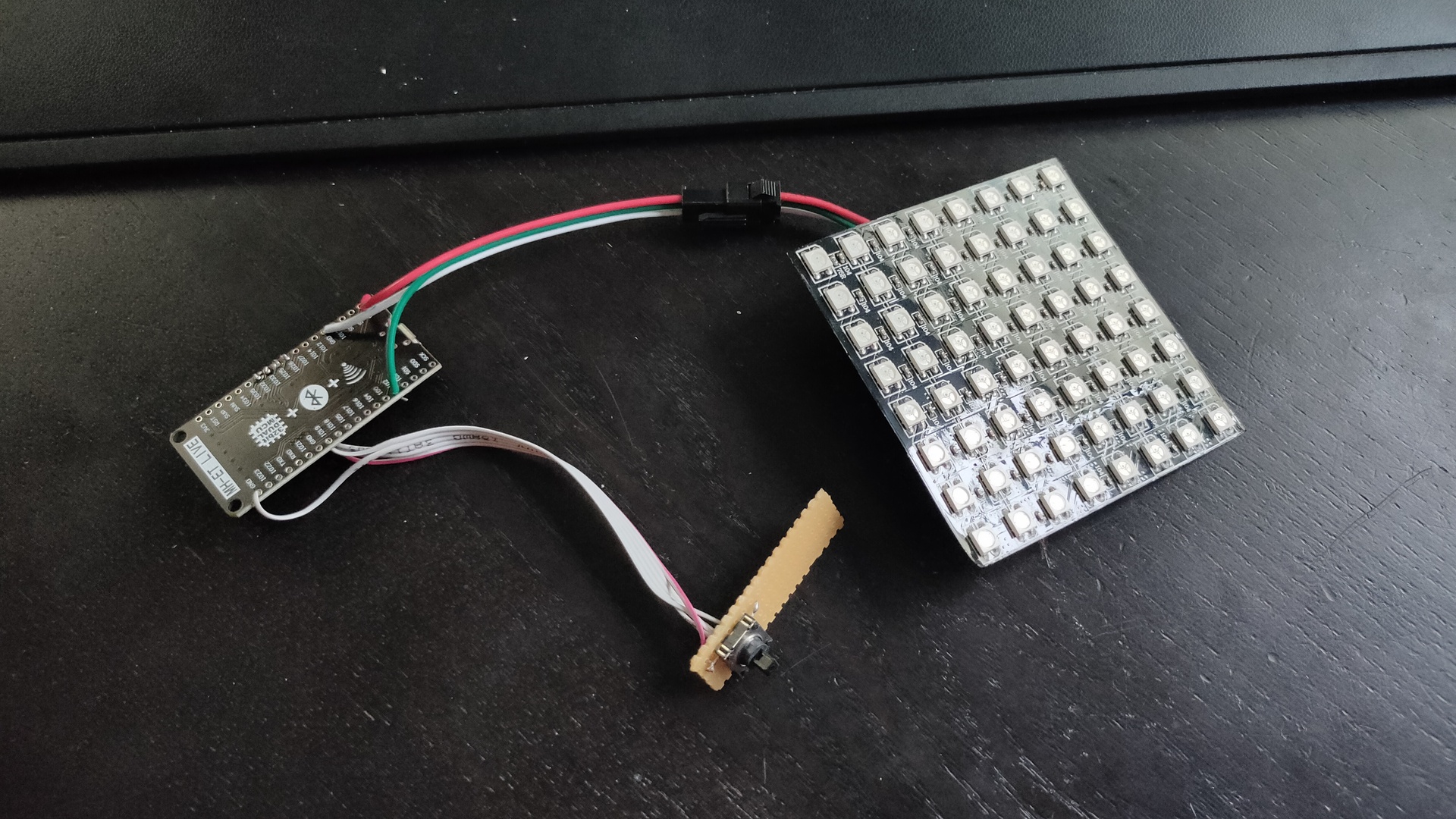
While doing stuff like, making our home a little greener. Smoking meat. Working on diorama’s and my Escape game. I found time to make this little maze game.
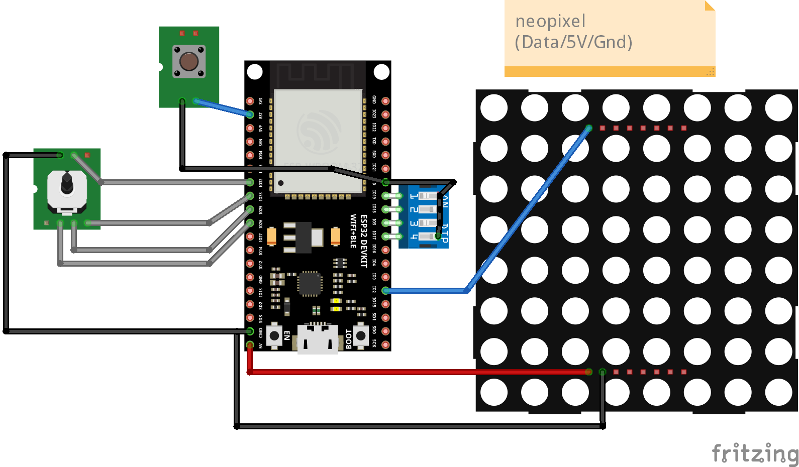
Using an ESP32, mini joystick and a 8×8 led matrix. The objective is to get to the other side of the invisible maze.
It is a blind maze, so you have to figure out the path by trail and error. I found it quite fun and entertaining. (Coline had a hard time finishing the mode 3 maze)
I’ve got 3 settings on the maze: 0 – There is a trail where you have been. 1 – No trail, but only red leds showing walls. 2 – No trail, red reds and a reset to square 0,0 .. so you have to remember the path you previously took.
I’ll add code and schematics tomorrow …
Light blue shows you where you have been
Mode 2 game, reset when hitting a wall
Hitting the end block!
Maze is static at the moment, i’m planning to implement a “Recursive division method” to generate the maze.
Code
#include <Arduino.h>
#include <Adafruit_NeoPixel.h>
// joystick pins
int up=33;
int down=25;
int left=32;
int right=26;
int cursor=32;
// 0 easy = trail // 1 only red walls // 2 = reset to 0.0
int mode=2;
//int trail=32;
int trail=0;
// Which pin on the Arduino is connected to the NeoPixels?
#define LED_PIN 2
// How many NeoPixels are attached to the Arduino?
#define LED_COUNT 64
// Declare our NeoPixel strip object:
Adafruit_NeoPixel strip(LED_COUNT, LED_PIN, NEO_GRB + NEO_KHZ800);
// bits set opening in square
// 2
// -----
// 1 | | 4
// -----
// 0
// so 5 is a passage from left to right (1+4)
int maze[8][8] = {
4,5,3,6,5,5,5,3,
6,5,11,12,5,3,6,9,
14,1,12,5,3,10,12,1,
12,5,5,3,10,12,5,3,
2,6,5,9,14,5,1,10,
10,10,6,5,9,6,5,9,
12,11,10,6,1,10,6,1,
4,9,12,13,5,13,13,1,
};
int displaymatrix[8][8] = {
{ 0,1,2,3,4,5,6,7 },
{ 15,14,13,12,11,10,9,8 },
{16,17,18,19,20,21,22,23},
{31,30,29,28,27,26,25,24},
{32,33,34,35,36,37,38,39},
{47,46,45,44,43,42,41,40},
{48,49,50,51,52,53,54,55},
{63,62,61,60,59,58,57,56}
};
int x = 0;
int y = 0;
void setup() {
// joy
pinMode(32, INPUT_PULLUP);
pinMode(33, INPUT_PULLUP);
pinMode(25, INPUT_PULLUP);
pinMode(26, INPUT_PULLUP);
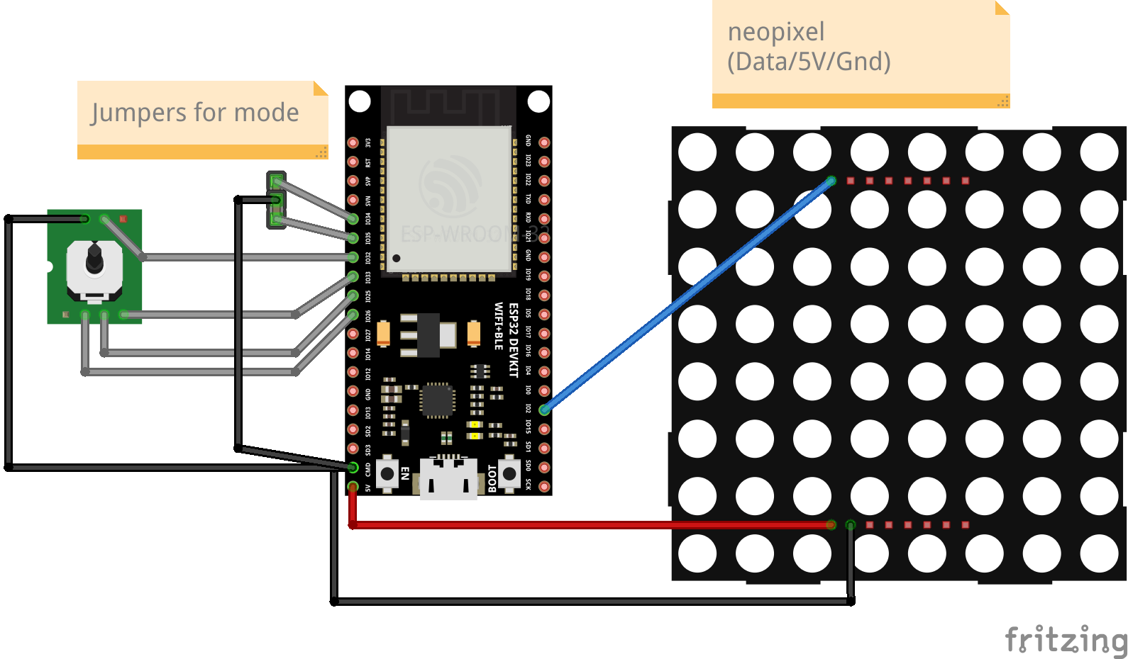
// mode set with jumpers
pinMode(34, INPUT_PULLUP);
pinMode(35, INPUT_PULLUP);
Serial.begin(115200);
strip.begin();
strip.show(); // Initialize all pixels to 'off'
strip.setBrightness(10);
// set begin and end pixel
strip.setPixelColor(displaymatrix[x][y], 0, 0, 255);
strip.setPixelColor(displaymatrix[7][7], 0, 255, 0);
strip.show();
//mode select
if (digitalRead(34) == 0) {
mode=0;
if (digitalRead(35) == 0) {
mode=2;
} else {
mode=1;
}
// finish effect
uint32_t Wheel(byte WheelPos) {
WheelPos = 255 - WheelPos;
if(WheelPos < 85) {
return strip.Color(255 - WheelPos * 3, 0, WheelPos * 3);
}
if(WheelPos < 170) {
WheelPos -= 85;
return strip.Color(0, WheelPos * 3, 255 - WheelPos * 3);
}
WheelPos -= 170;
return strip.Color(WheelPos * 3, 255 - WheelPos * 3, 0);
}
// reset to start (mode 2)
void reset2start() {
strip.setPixelColor(displaymatrix[x][y], 0, 0, 0);
strip.show();
x = 0;
y = 0;
strip.begin();
strip.show(); // Initialize all pixels to 'off'
strip.setBrightness(10);
strip.setPixelColor(displaymatrix[x][y], 0, 0, 255);
strip.setPixelColor(displaymatrix[7][7], 0, 255, 0);
strip.show();
}
// finish effect
void rainbow(uint8_t wait) {
uint16_t i, j;
for(j=0; j<256; j++) {
for(i=0; i<strip.numPixels(); i++) {
strip.setPixelColor(i, Wheel((i+j) & 255));
}
strip.show();
delay(wait);
}
}
void loop() {
int isUp = (bitRead(maze[x][y], 1));
int isRight = (bitRead(maze[x][y], 2));
int isDown = (bitRead(maze[x][y], 3));
int isLeft = (bitRead(maze[x][y], 0));
if (digitalRead(up) == 0) {
if (isUp == 1){
strip.setPixelColor(displaymatrix[x][y], 0, 0, trail);
x++;
if ( x > 7) { x=7;}
strip.setPixelColor(displaymatrix[x][y], 0, 0, 255);
strip.show();
} else {
strip.setPixelColor(displaymatrix[x][y], 255, 0, 0);
strip.show();
if (mode == 2){
delay(1000);
reset2start();
}
}
}
if (digitalRead(down) == 0) {
if (isDown == 1){
strip.setPixelColor(displaymatrix[x][y], 0, 0, trail);
x--;
if ( x < 0) { x=0;}
strip.setPixelColor(displaymatrix[x][y], 0, 0, 255);
strip.show();
} else {
strip.setPixelColor(displaymatrix[x][y], 255, 0, 0);
strip.show();
if (mode == 2){
delay(1000);
reset2start();
}
}
}
if (digitalRead(left) == 0) {
if (isLeft == 1){
strip.setPixelColor(displaymatrix[x][y], 0, 0, trail);
y--;
if ( y < 0) { y=0;}
strip.setPixelColor(displaymatrix[x][y], 0, 0, 255);
strip.show();
} else {
strip.setPixelColor(displaymatrix[x][y], 255, 0, 0);
strip.show();
if (mode == 2){
delay(1000);
reset2start();
}
}
}
if (digitalRead(right) == 0) {
if (isRight == 1){
strip.setPixelColor(displaymatrix[x][y], 0, 0, trail);
y++;
if ( y > 7) { y=7;}
strip.setPixelColor(displaymatrix[x][y], 0, 0, 255);
strip.show();
} else {
strip.setPixelColor(displaymatrix[x][y], 255, 0, 0);
strip.show();
if (mode == 2){
delay(1000);
reset2start();
}
}
}
if (x ==7 && y == 7){
strip.begin();
strip.show(); // Initialize all pixels to 'off'
rainbow(20);
}
delay(200);
}
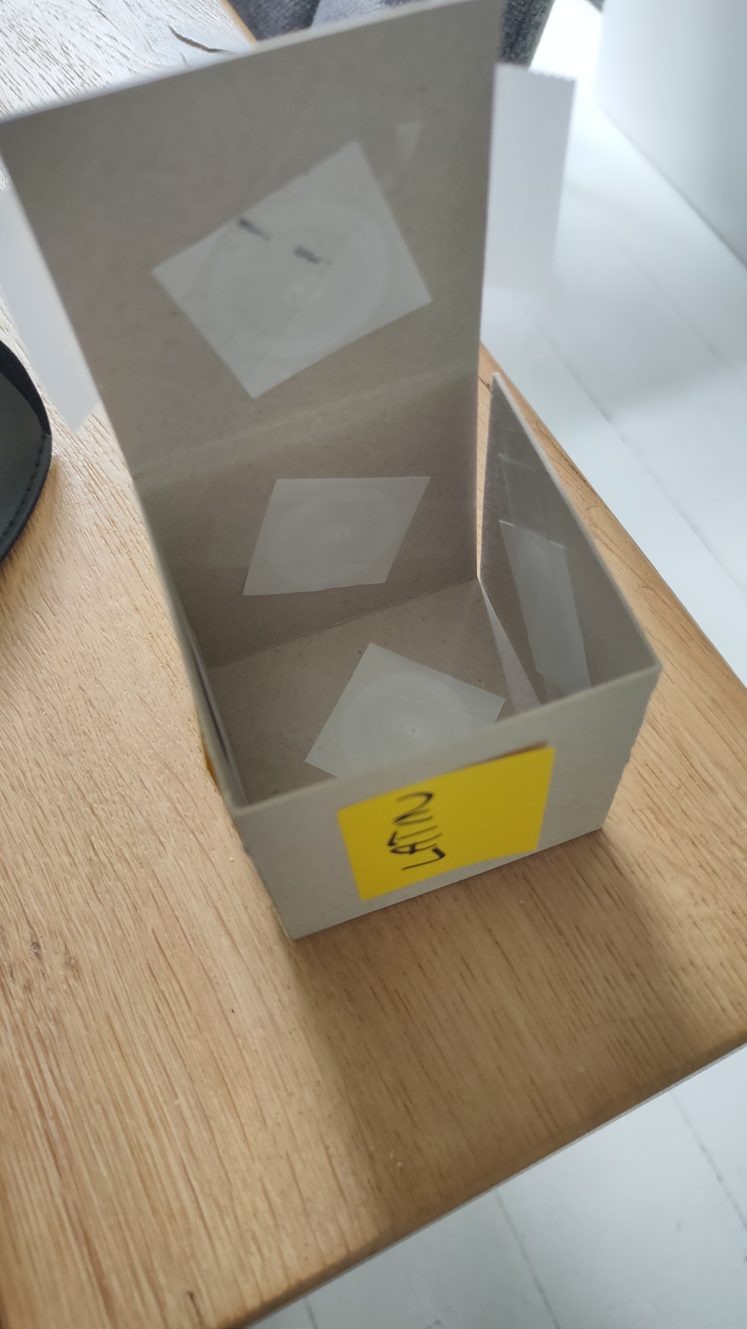
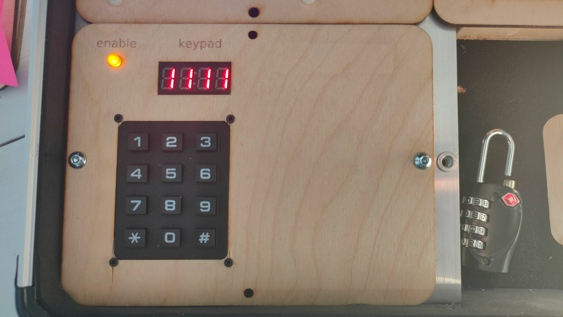
The codes are entered using a keypad (Arduino) and send via MQTT
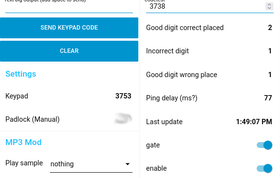
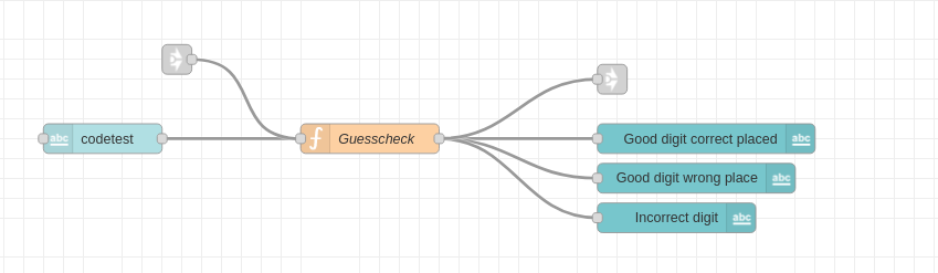
Node Red Dash board
Code
var code = global.get("mysetcode");
var good = 0;
var wrong = 0;
var wrongplace = 0;
var match = false;
var wrongchars = 0;
var wrongplaced = 0;
var goodchars = 0;
var payloadcode = msg.payload.toString();

var usr_input = Array.from(payloadcode);
var secret_code = Array.from(code);
var secret_code1 = secret_code;

if (msg.payload === code) {
    match = true;
}
var result = "";

for (var i = 0; i < 4; i++) {
    var found = false;
    if (usr_input[i] === secret_code[i]) {
    usr_input[i] = "a";
    secret_code[i] = "b";
        good = good + 1;

    }
}

for (var i = 0; i < 4; i++) {
    var found = false;
    for (var j = 0; j < 4; j++) {
        if (usr_input[i] === secret_code[j]) {
                found = true;
        }
    }
        if (!found) {
    wrong = wrong + 1;
    }
}

wrongchars = wrong - good;
wrongplaced = 4 - good - wrongchars;

msg.goodchars = good;
msg.wrongchars = wrongchars;
msg.wrongplace = wrongplaced;
msg.result = result;
msg.match = match;
return msg;
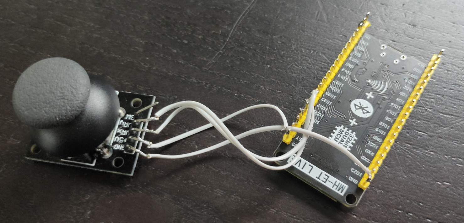
When you need a large digital joystick, but only got an analog one. You can use below code to make the joystick act as a digital one.
I’ve played with analog joysticks on digital pins also, it can be done. But it can be buggy, and needs extra code.
Note: The joystick pins are marked with 5V, but when you use a Arduino which can only read till 3.3V using its ADC (Analog Digital Convertors), you can get some weird readings. When moving down and left is reads okay, but up and right react as being connected together! Just try it with 3.3V or use a resistor.
Above shows a ESP32, but below code has Arduino Nano pin names, change accordingly.
CODE
The code gives you a direction only once, you will need to move the stick to the middle position first and then move again.
Below gave me readings between 0 and 1024 (10 bits) Hence the between 350 and 650 for the middle position.
Most will give you a reading between 0 and 4096.
Want to set the resolution yourself?
analogReadResolution(10); // 10 bits
int val1 =0;
int val2 =0;

void setup()
{
    Serial.begin(9600);
}

void loop()
{
    int sensorValue1 = analogRead(A0);
    int sensorValue2 = analogRead(A1);

    if (sensorValue1 > 650){
      if (val1 == 0){
      Serial.print("DOWN");
      Serial.println(" ");
      val1=1;
      }
    }
    else if (sensorValue1 < 350){
      if (val1 == 0){
       Serial.print("UP");
      Serial.println(" ");
      val1=1;
      }
    }
    else if (sensorValue2 > 350 && sensorValue2 < 650){
      val1=0;
    }


    if (sensorValue2 > 650){
      if (val2 == 0){
      Serial.print("LEFT");
      Serial.println(" ");
      val2=1;
      }
    }
    else if (sensorValue2 < 350){
      if (val2 == 0){
       Serial.print("RIGHT");
      Serial.println(" ");
      val2=1;
      }
    }
    else if (sensorValue2 > 350 && sensorValue2 < 650){
      val2=0;
    }

    delay(100);
}
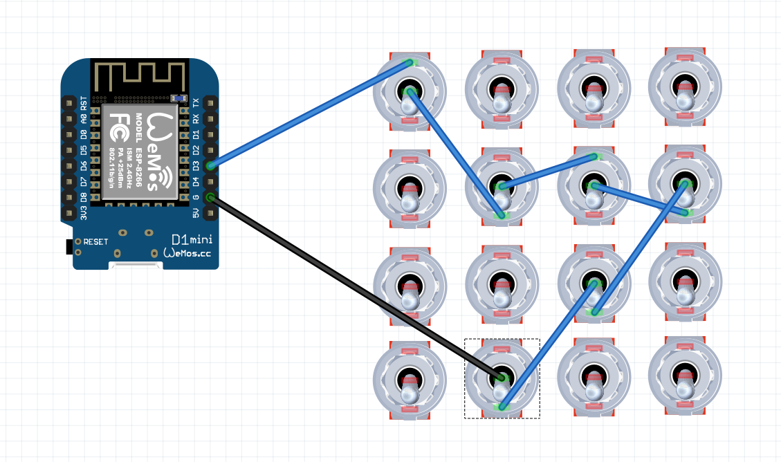
I was thinking of a easier setup which is “static”. Mine has a 65535 possibility setup, but you can make an easy puzzle with below setup.
Set D3 to pinMode(D3, INPUT_PULLUP);
Notice that I’ve placed the wires for some switches at the bottom, so these switches need to be set in the other direction “off” than the others. Only 7 switches matter, you could use all of them. When using a switch with only two connections, place the switch upside-down. Now OFF is switch with ON.
These are last weeks findings, I will add to this page when I discover other useful things.
Platformio
always include “Arduino.h”
Order of functions matter! (Not with Arduino IDE)
setup serial monitor speed in platformio.ini monitor_speed = 115200
Arduino IDE
Build error “panic: runtime error: index out of range [3] with length 3” or length 4. Code probably correct, build with another board and build+upload with correct board as workaround.
Generic
Using a SSD1306 with other pins? For example with Adafruit_SSD1306.h in setup(){ place Wire.begin(5,4);
I’ve build a IR Blaster in the past and tested IR with EspEasy Dev. I’m not happy with my Harmony Hub. Not so much control as i like to have.
So now OpenMqttGateway with IR.
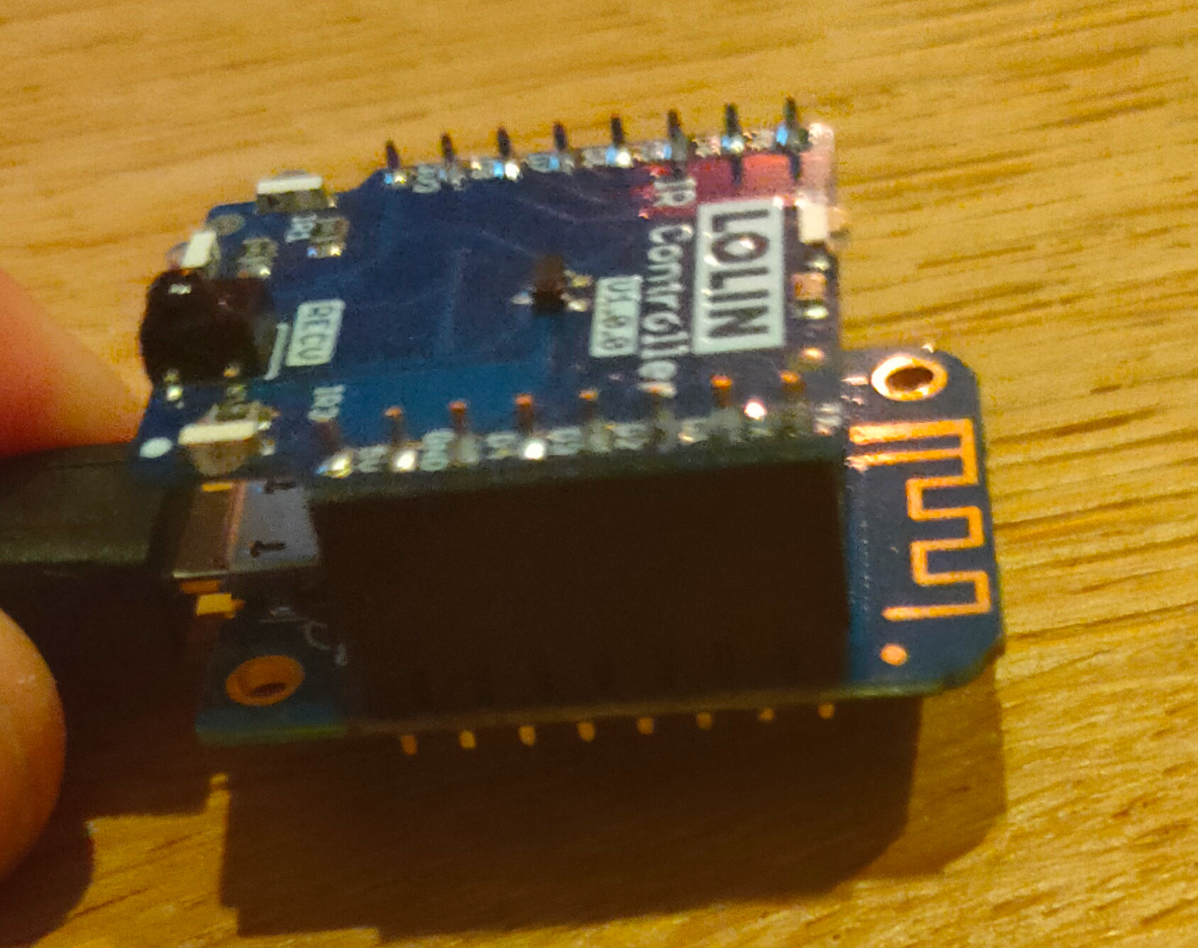
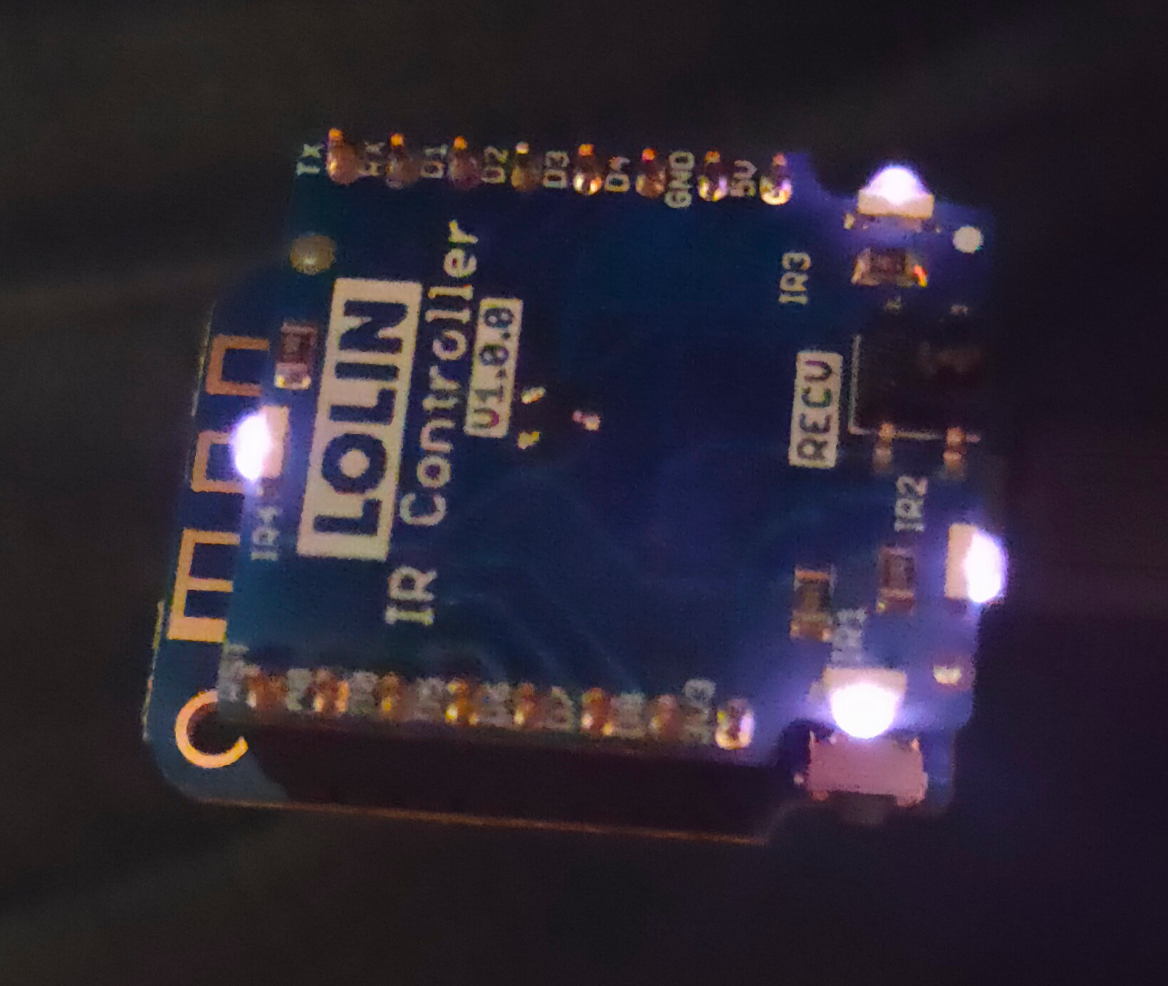
Wemos D1 with IR shieldIR Signal (visible using mobile phone)
I’ve installed platformio in the past. Not really a fan of visual-code i’m showing you the process on CLI
We can’t use the webinstaller or a precompiled binary because we need to change GPIO ports
wget https://github.com/1technophile/OpenMQTTGateway/releases/download/v1.5.0/nodemcuv2-ir-libraries.zip
wget https://github.com/1technophile/OpenMQTTGateway/archive/refs/tags/v1.5.0.tar.gz
tar xzvf v1.5.0.tar.gz
cd v1.5.0/libs
unzip ../../nodemcuv2-ir-libraries.zip
cd ..
edit platformio.ini
remove ; from
default_envs = nodemcuv2-ir
vi main/config_IR.h
search for LOLIN, edit and change into 0 (GPIO 0 = D3)

build and upload
pio run --target upload --upload-port /dev/ttyUSB0
build and upload with flash erase
pio run --target erase --target upload --upload-port /dev/ttyUSB0

clean the environment when needed
pio run -t clean
Now you will get a Access Point, connect and enter your Wifi network information and mqtt server.
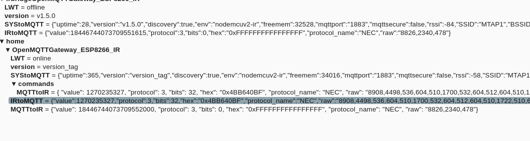
When connected you will see the IR codes and if you installed mqtt support in home assistant it will see the mqtt topics.
I’ve copied a json output as was send by my IR remote. Below an example using mosquitto_pub to send codes.
Why use platformio? I know Arduino IDE is easier for starters. Platformio is far more flexible, you can make projects with their own versions of libraries. I like CLI, easier to do version control (git)
pip install -U platformio
pio upgrade
pio update
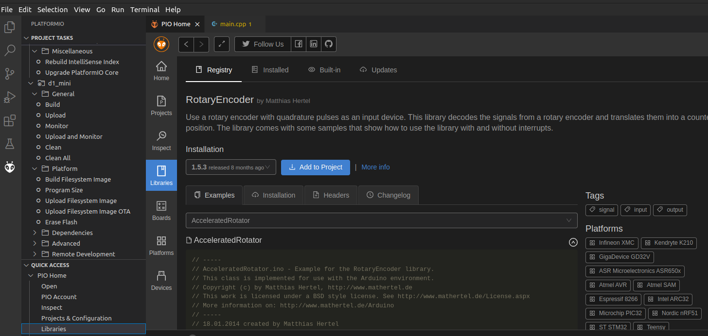
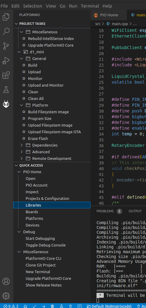
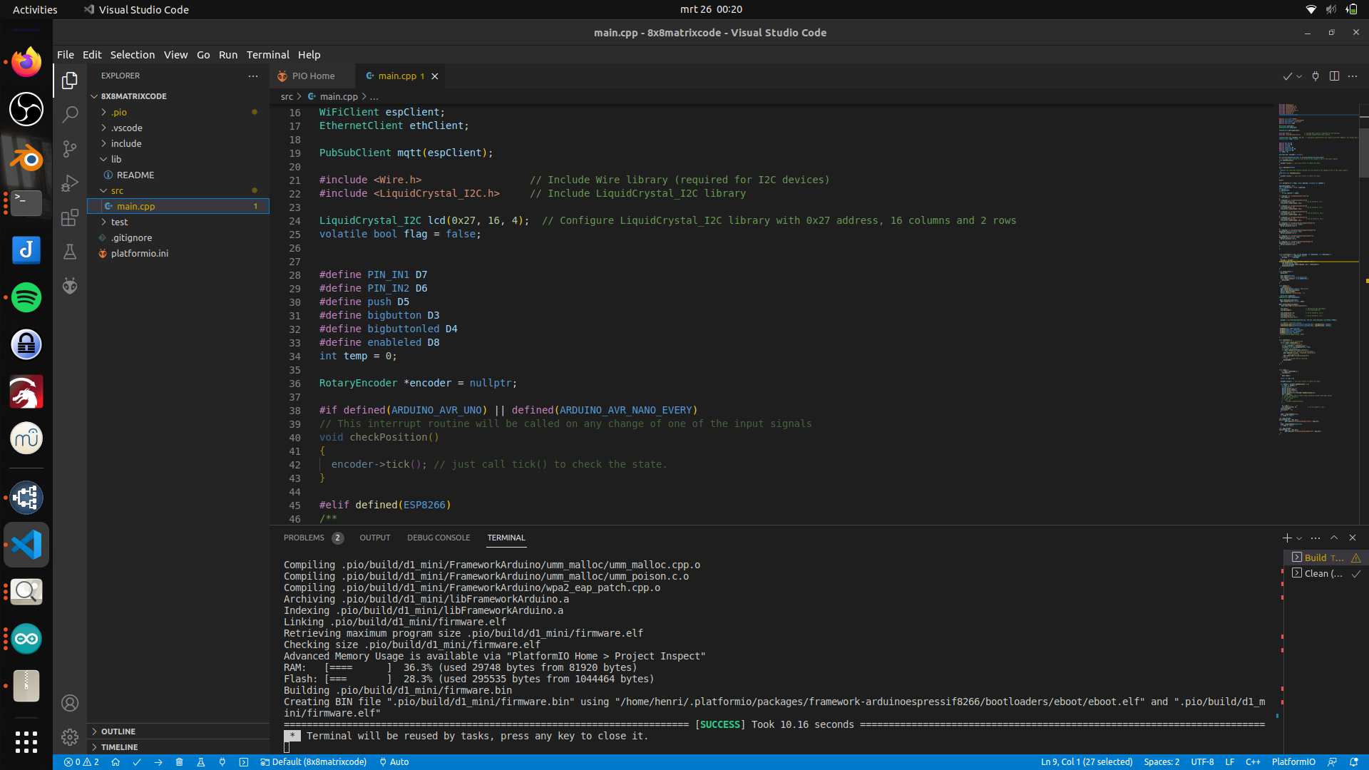
Some screenshots of my visual code platformio
"If something is worth doing, it's worth overdoing."