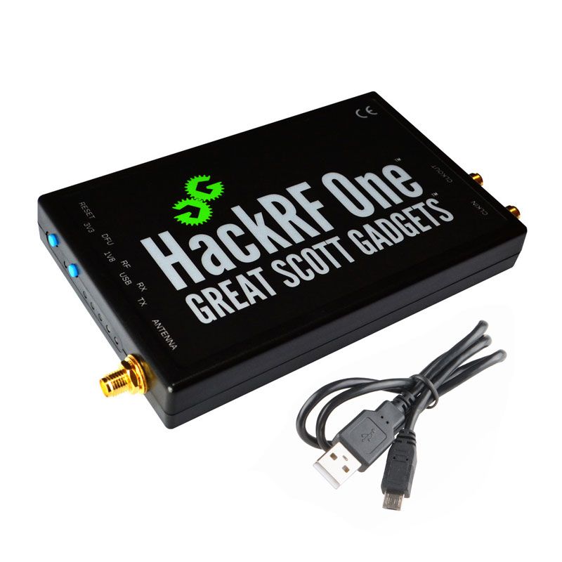
HackRF One from Great Scott Gadgets is a Software Defined Radio peripheral capable of transmission or reception of radio signals from 1 MHz to 6 GHz. Designed to enable test and development of modern and next generation radio technologies, HackRF One is an open source hardware platform that can be used as a USB peripheral or programmed for stand-alone operation.
1 MHz to 6 GHz operating frequency
half-duplex transceiver
up to 20 million samples per second
8-bit quadrature samples (8-bit I and 8-bit Q)
compatible with GNU Radio, SDR#, and more
software-configurable RX and TX gain and baseband filter
software-controlled antenna port power (50 mA at 3.3 V)
SMA female antenna connector
SMA female clock input and output for synchronization
convenient buttons for programming
internal pin headers for expansion
Hi-Speed USB 2.0
USB-powered
open source hardware
I’ve got dvb alternative below now. Hackrf cannot be bought anymore
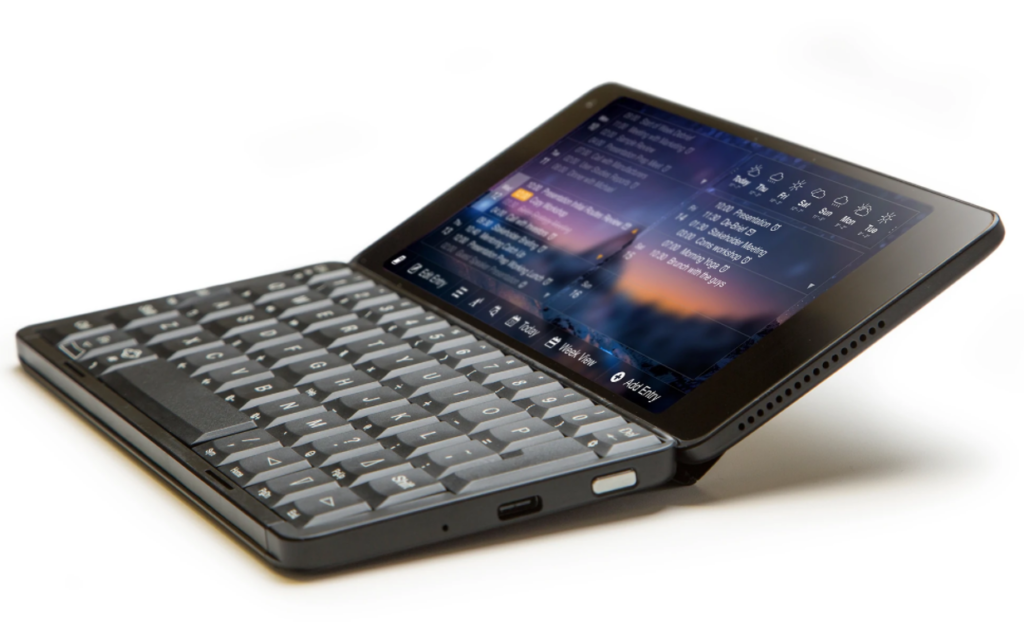
Gemini PDA
Android / Linux PDA
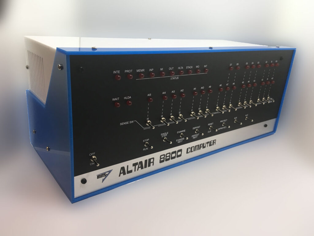
ALTAIR 8800 EMULATOR KIT
The Altair 8800 is a microcomputer designed in 1974 and based on the intel 8080 CPU. Using only switches to program and leds for output. Even my DIY build computer has a hex keyboard input and 7segments display.
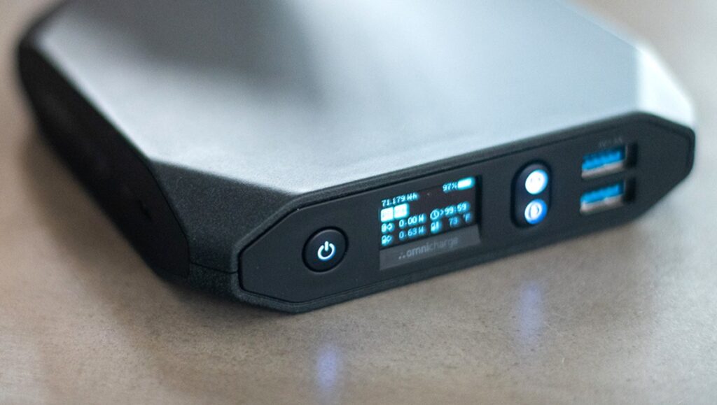
Omnicharge 20+ Usb C Wireless Power Bank 20,000mAh Power Delivery 3.0 + Quick Charge 3.0
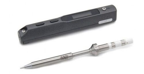
You can use this as a mobile soldering station using a TS100 soldering iron.
HAVE IT
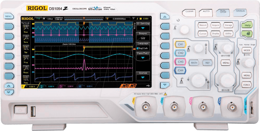
Rigol Oscilloscope DS1054
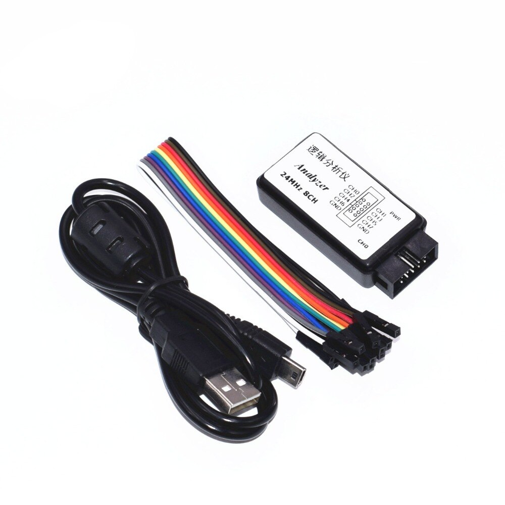
HAVE Z VERSION (LOGIC ANALIZER)
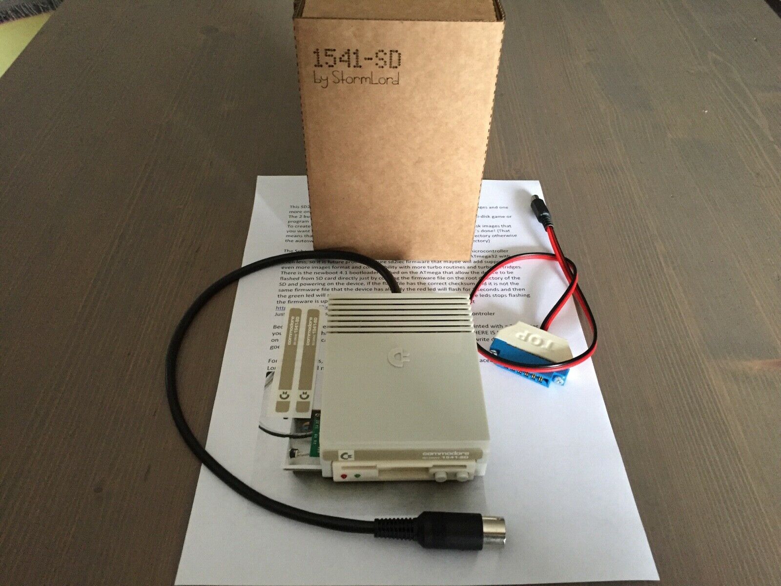
SDCard reader for C64 and other commodore machines
Got this one now, superb. And a Meatloaf DIY
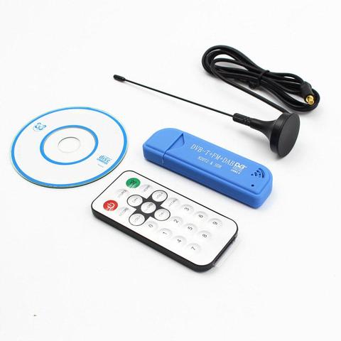
Tv Stick Dab Fm Dvb-t RTL2832 R820T Sdr RTL-SDR Dongle Stick Digitale Tv Tuner Ontvanger TVSDVBS816
Modded this one, as part of my modular amiga system where i wanted to remake every part onto 10×15 euro prints. So i could swap things out for other boards.
Memory expansion
512k .. missing in action Go a new one in … ?
Boot selector
Swaps df0 and df1 DIY version was a wirewrap ic socket with a cross switch, now i have a Gotek buffered switching module with can be actvated with a keystroke. (Gotek post)
Keyboard mod
Hidden key (in the space of the stands, which triggered a extra key stroke)
Kickstart selector
A print you can insert in the ROM socket of your amiga. Had only 1.2 and 1.3. Now there are many .. like diagnostic roms. I made a altered 1.2 version .. which was unusable .. i f*cked it up
SID mod
Added a sid parallel on the 8020 CIA chip
Gotek driver emulator
I made a arduino version to read disks. (Other post) But this is a disk image drive emulator. See Gotek post
Boot sector warn
Piezo beeper which warned me when a boot sector was being written (virus alert)
Sound filter fix
Amiga audio filter enhancer, using capacitors and resistors
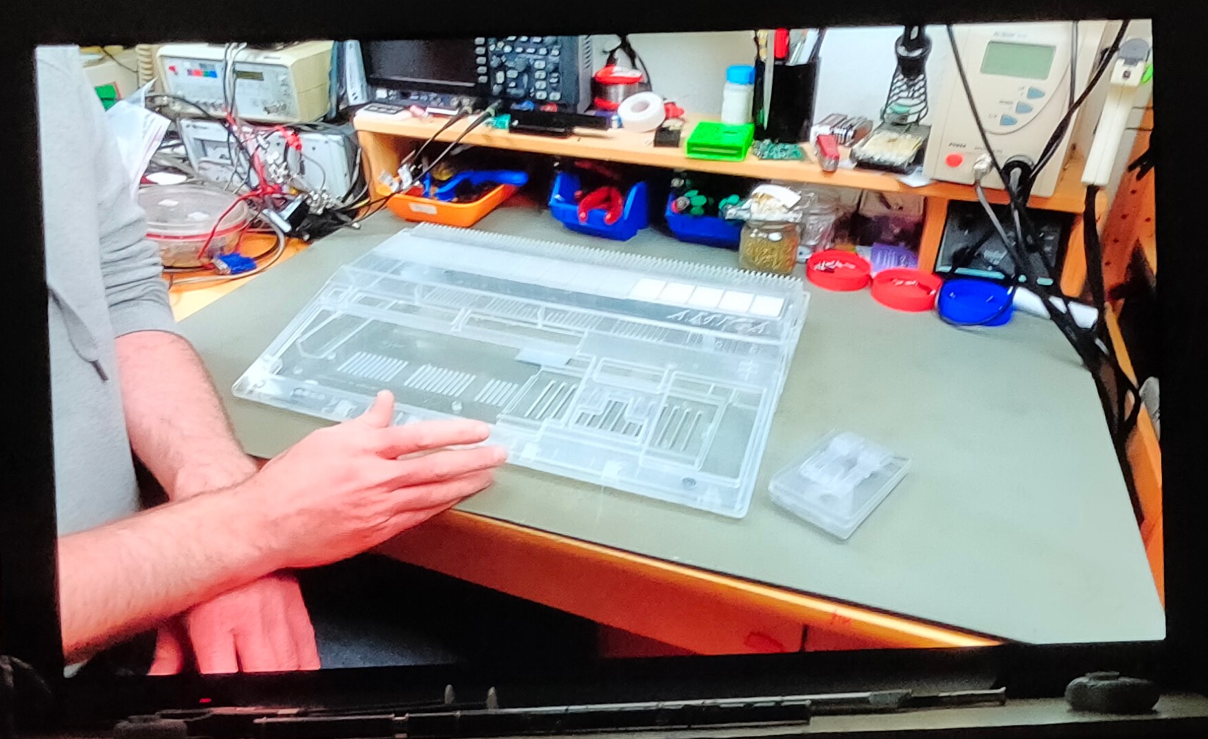
Trying to fix a computer from my computer collection.
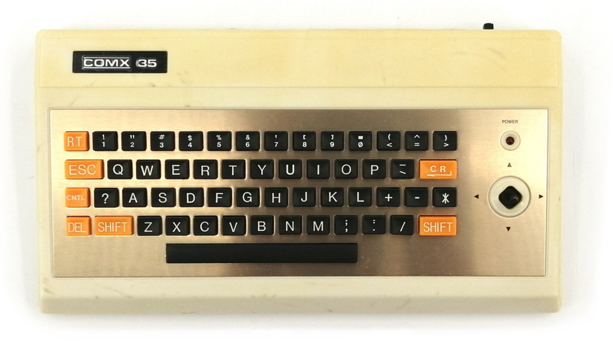
Comx-35 (1983)
RCA 1802 CPU @ 2.8 Mhz
32K Memory
Apparenty something wrong with the graphics chip.
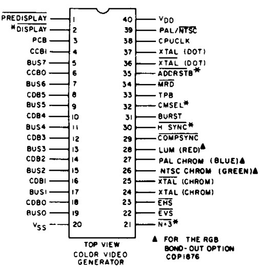
The COMX uses the RCA CDP1869 and CDP1870 Video Interface System (VIS), consisting of the CDP1869 address and sound generator and the CDP1870 colour video generator.
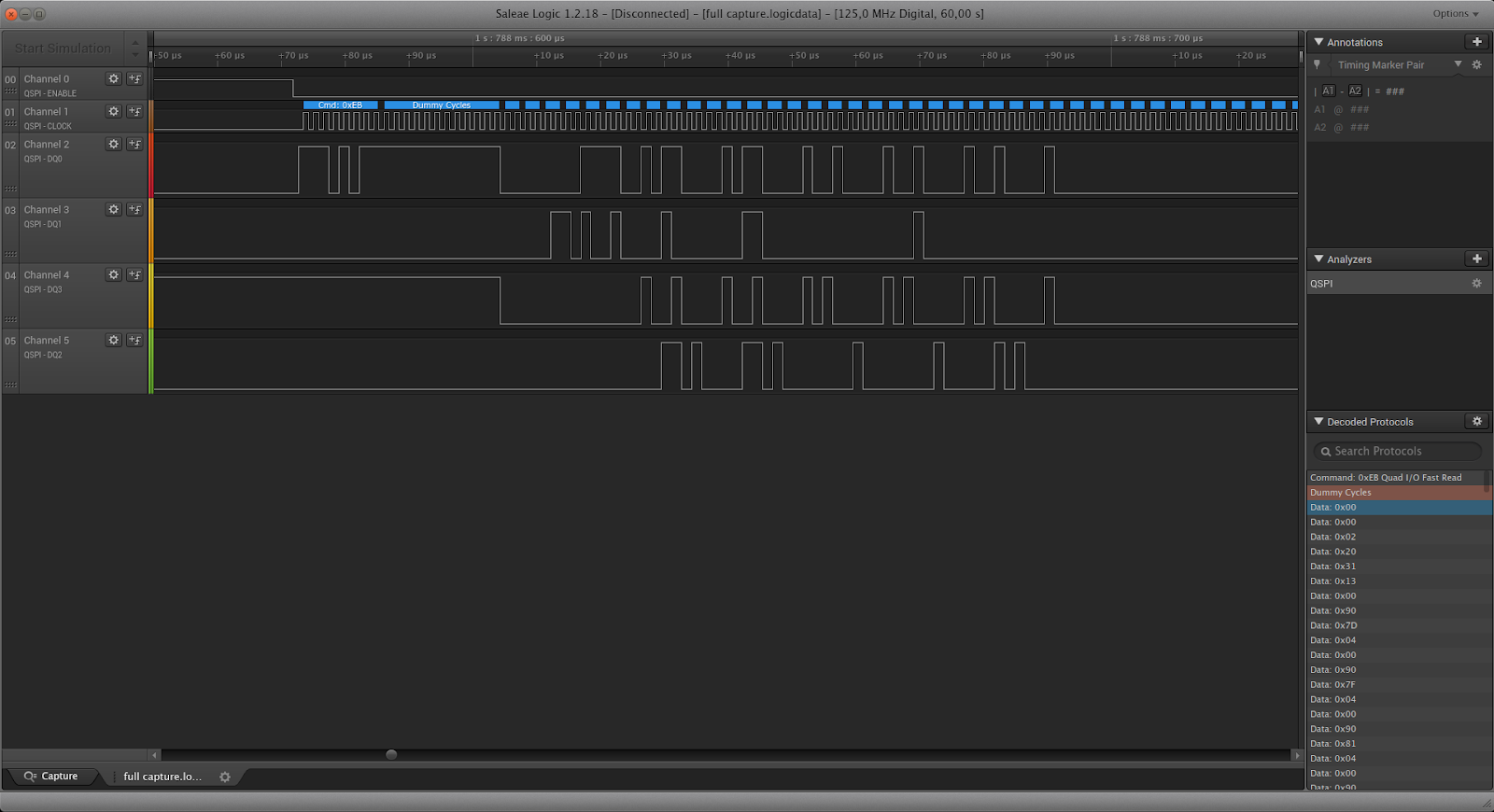
Maybe next to try : checking signals using a Logic Analyzer
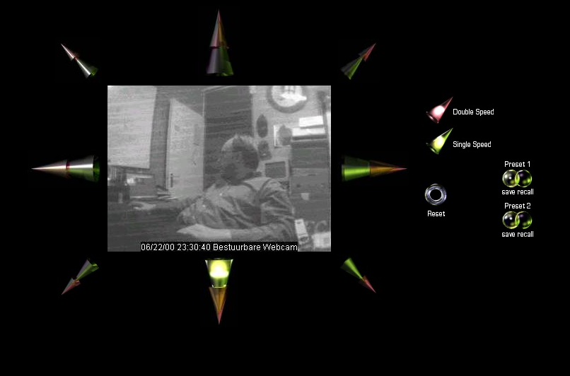
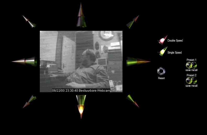
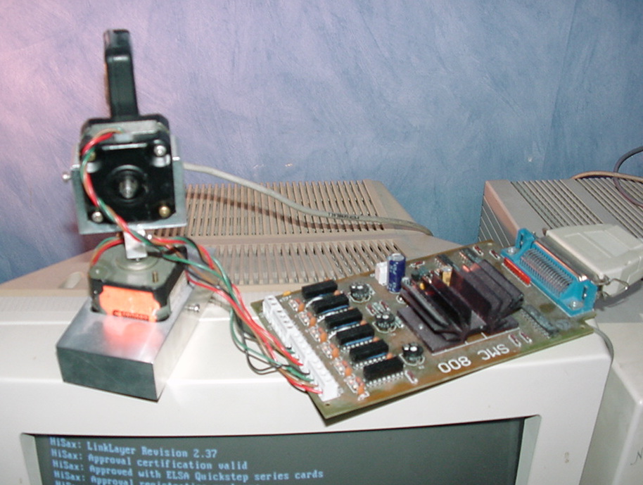
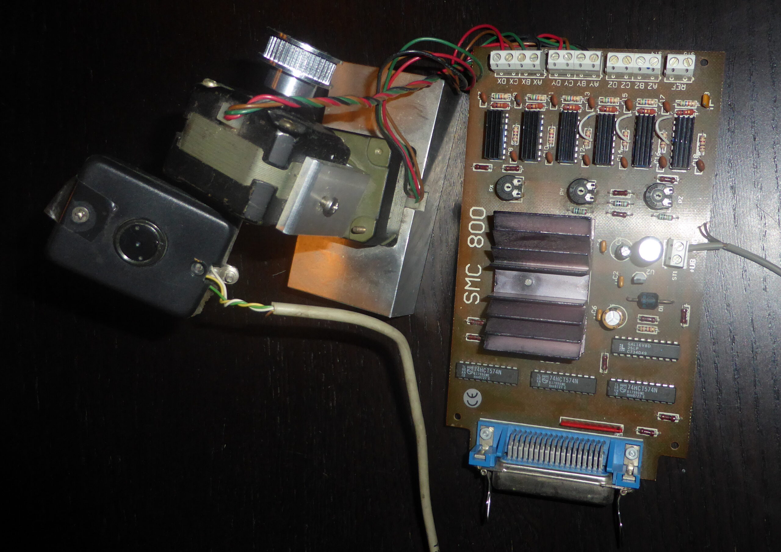
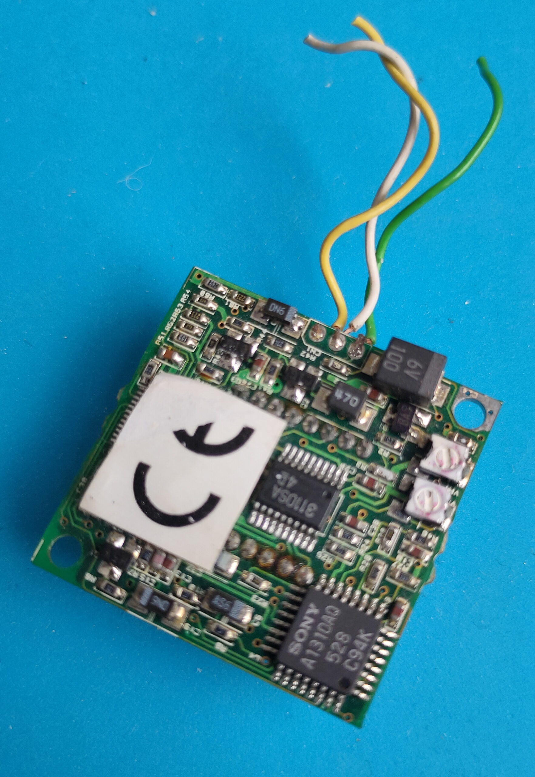
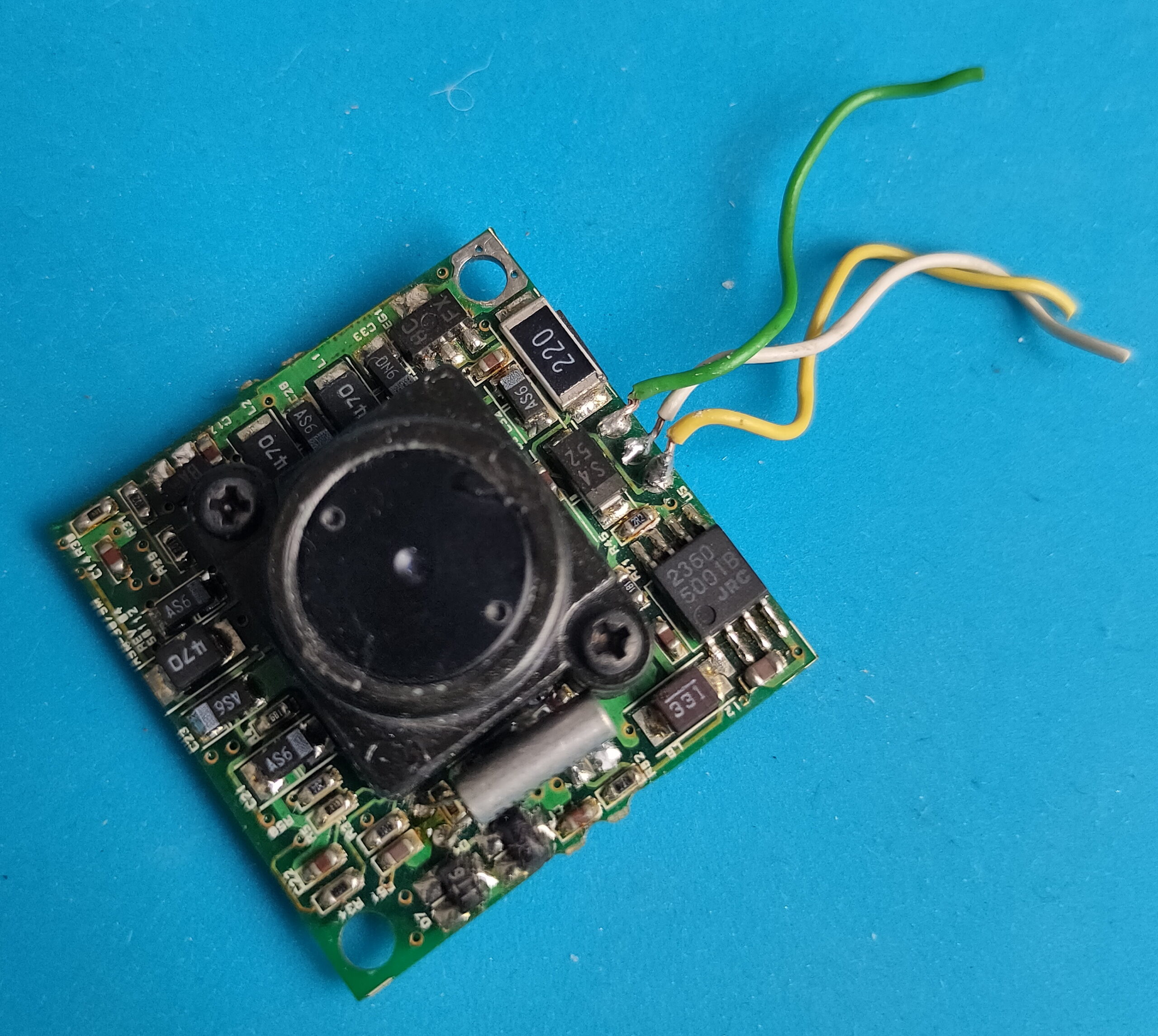
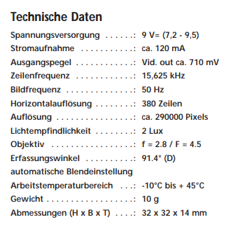
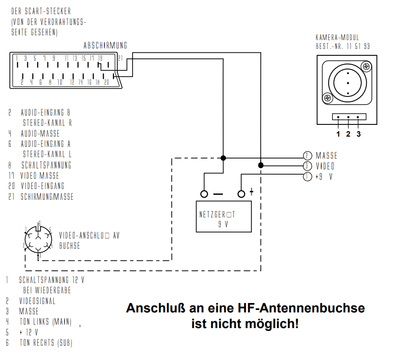
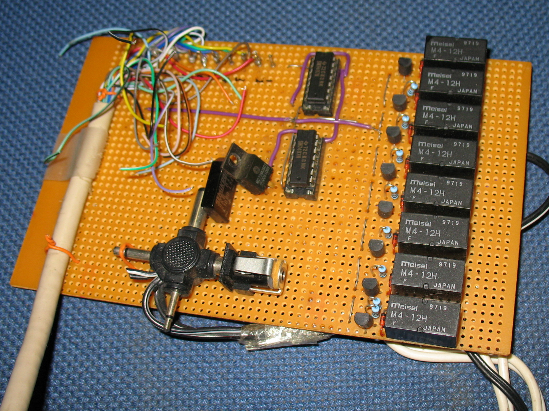
Using a steppermotor controller with two motors. A video capturing device (videoblaster) and a mini B/W camera.
Web interface with glassbuttons effects which i rendered using Bryce.
Up/down/left/right and diagonal
Red double speed green single speed
Reset view
2 Presets with save and recall
Setup with parallel cable
Written software in html and some CGI scripts. Perl and C.
#include <asm/io.h>

# C Code for moving left

int main(int agrc,char agrv[])
{
  int i,wachten;
  int richting1[8]={0x27,0x2d,0x1c,0x0d,0x03,0x09,0x38,0x29};
  int richting2[8]={0x29,0x38,0x09,0x03,0x0d,0x1c,0x2d,0x27};
  ioperm(0x378,3,1);
  ioperm(0x37a,3,1);
  wachten=100;


for (i=0; i<=7; i=i+1)
        {
        outb(richting2[i], 0x378);
        outb(1, 0x37a);
        usleep(wachten);
        outb(0, 0x37a);
        usleep(wachten);
        outb(1, 0x37a);
        usleep(wachten);
        }

 return(0);
}
#!/usr/bin/perl
# Perl CGI script

# Uses 204 no content trick to stay on same page
use LWP::Simple;
my $img = get ('http://10.1.0.1/cgi-bin/left.cgi');
print "Status: 204 No content\n\n";
Streaming video was done using progressive JPG push. Later i used the capturing command in the loop below.
#!/bin/sh

# push jpg, and update after 1sec
# output mime header

echo Content-type: multipart/x-mixed-replace;boundary=--WebcamRules\n
echo
echo --WebcamRules

# create stream

while true; do
   echo Content-type: image/jpeg
   echo
   cat /var/lib/httpd/htdocs/webcam.jpg
   echo
   echo --WebcamRules

   sleep 1
done
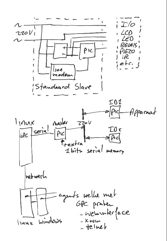
The date of this post is when we worked on GMC’s GPC, but i’ll post some other own made hardware related to domotica.
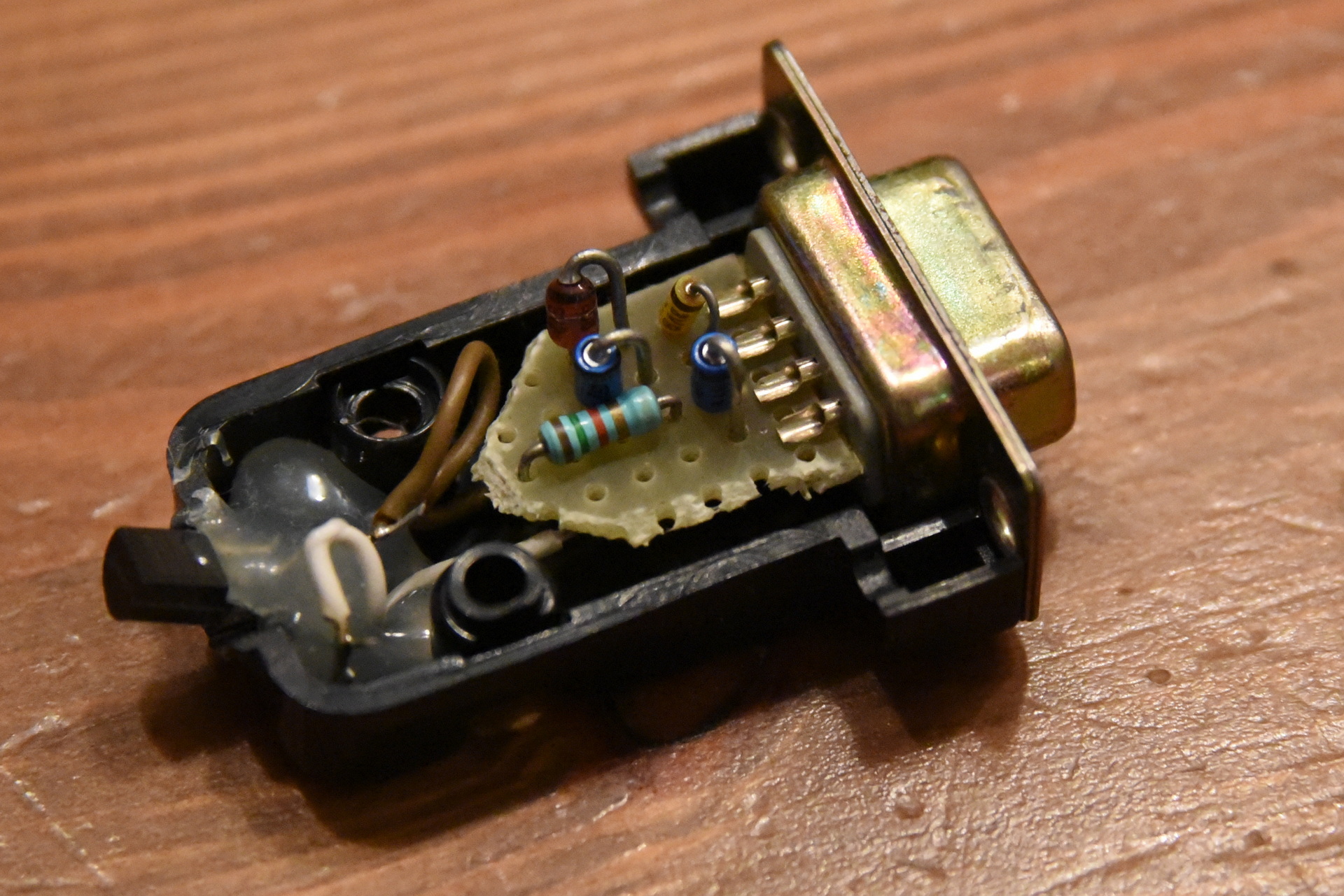
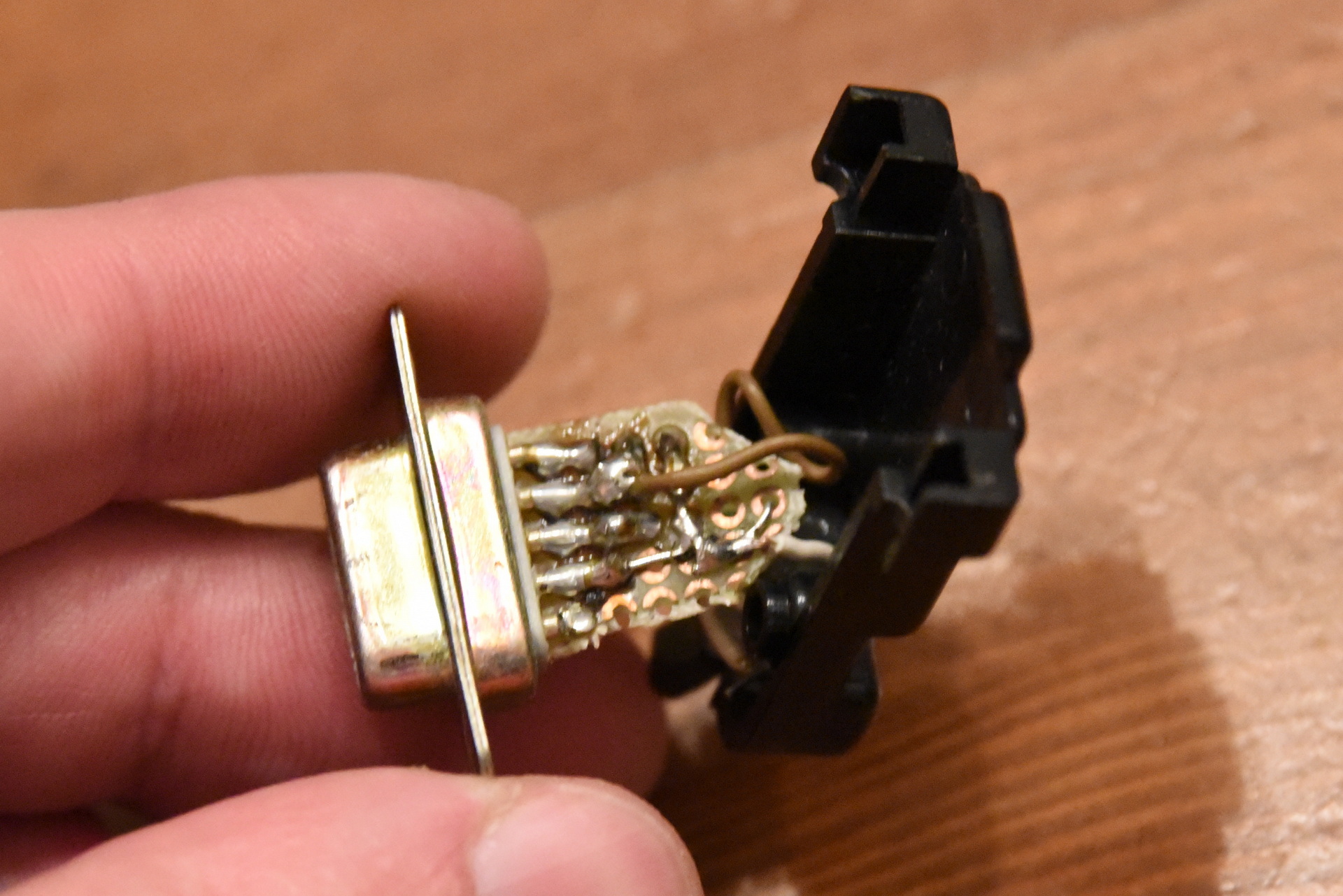
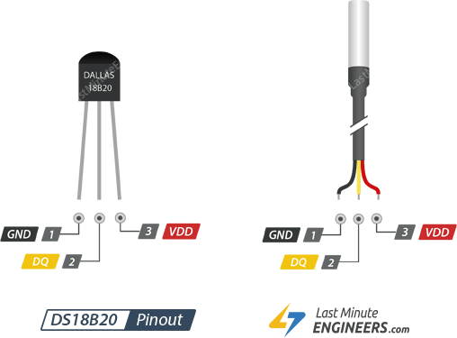
Relais card + one wire temperature sensor (rs232)1Wire to RS232DS18B20
GPC Original Page: https://gpc.metro.cx/gpc/README
This DIY home automation was written by GMC in C. Later we made little microcontroller prints, which could control/switch lights and more.
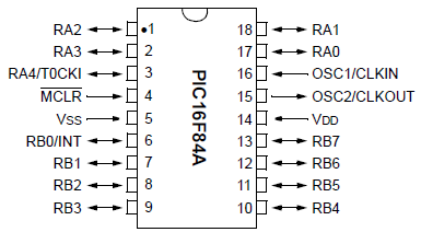
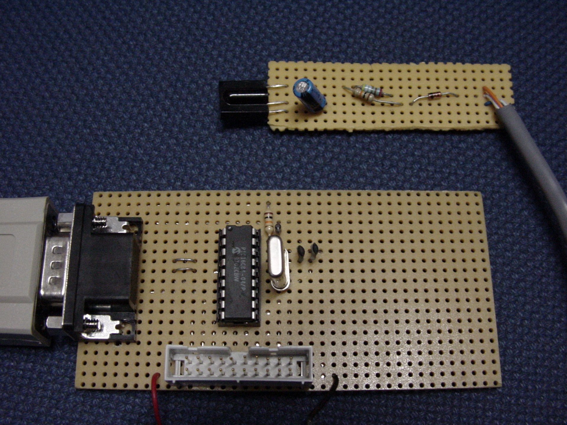
PIC16x84
We uses GPASM as assembler
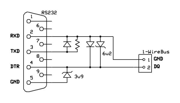
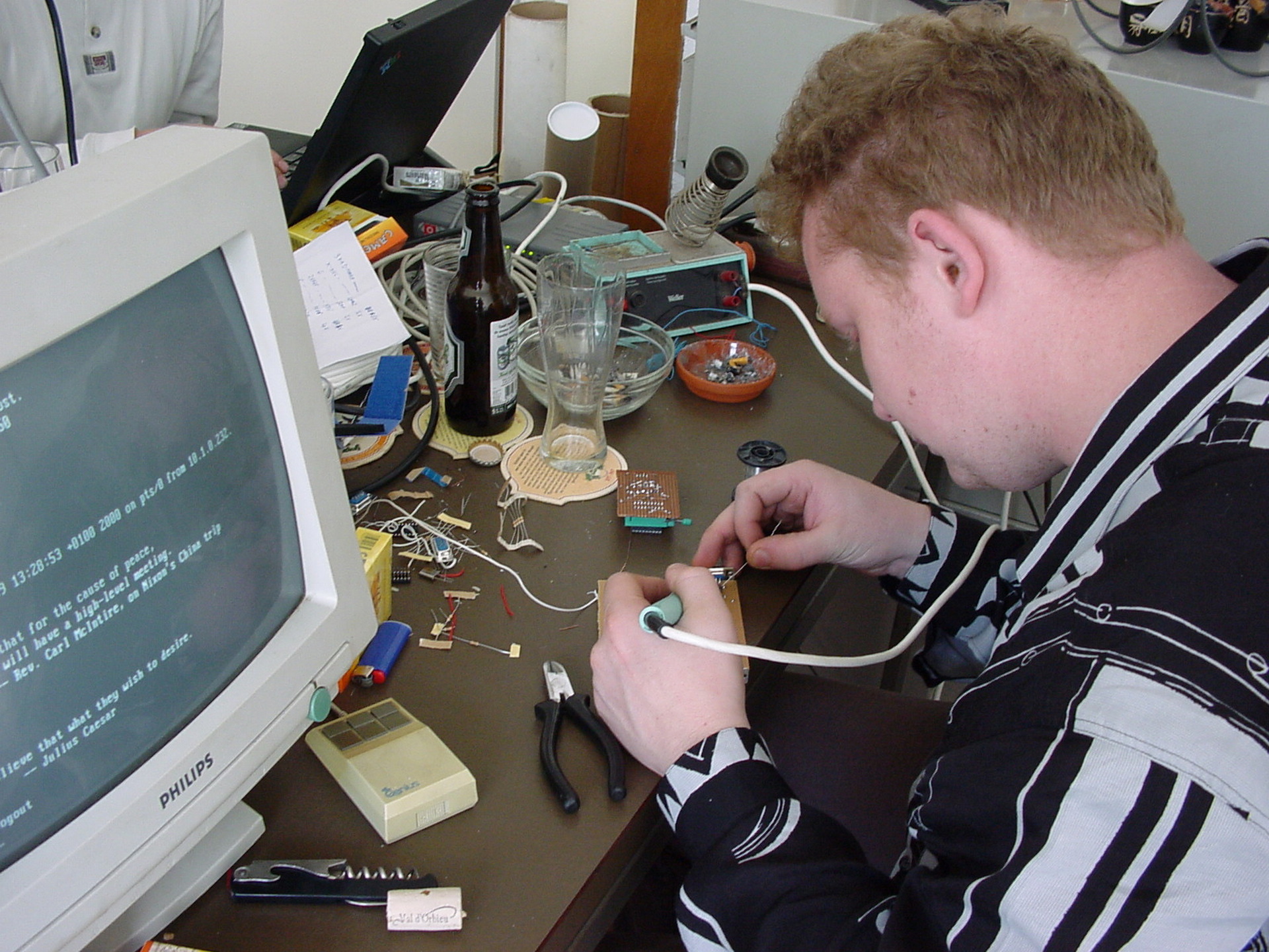
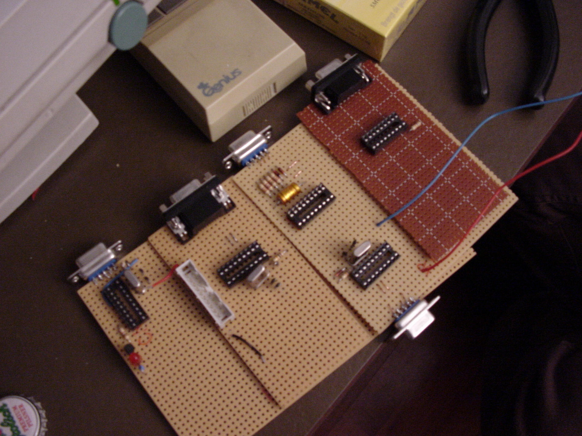
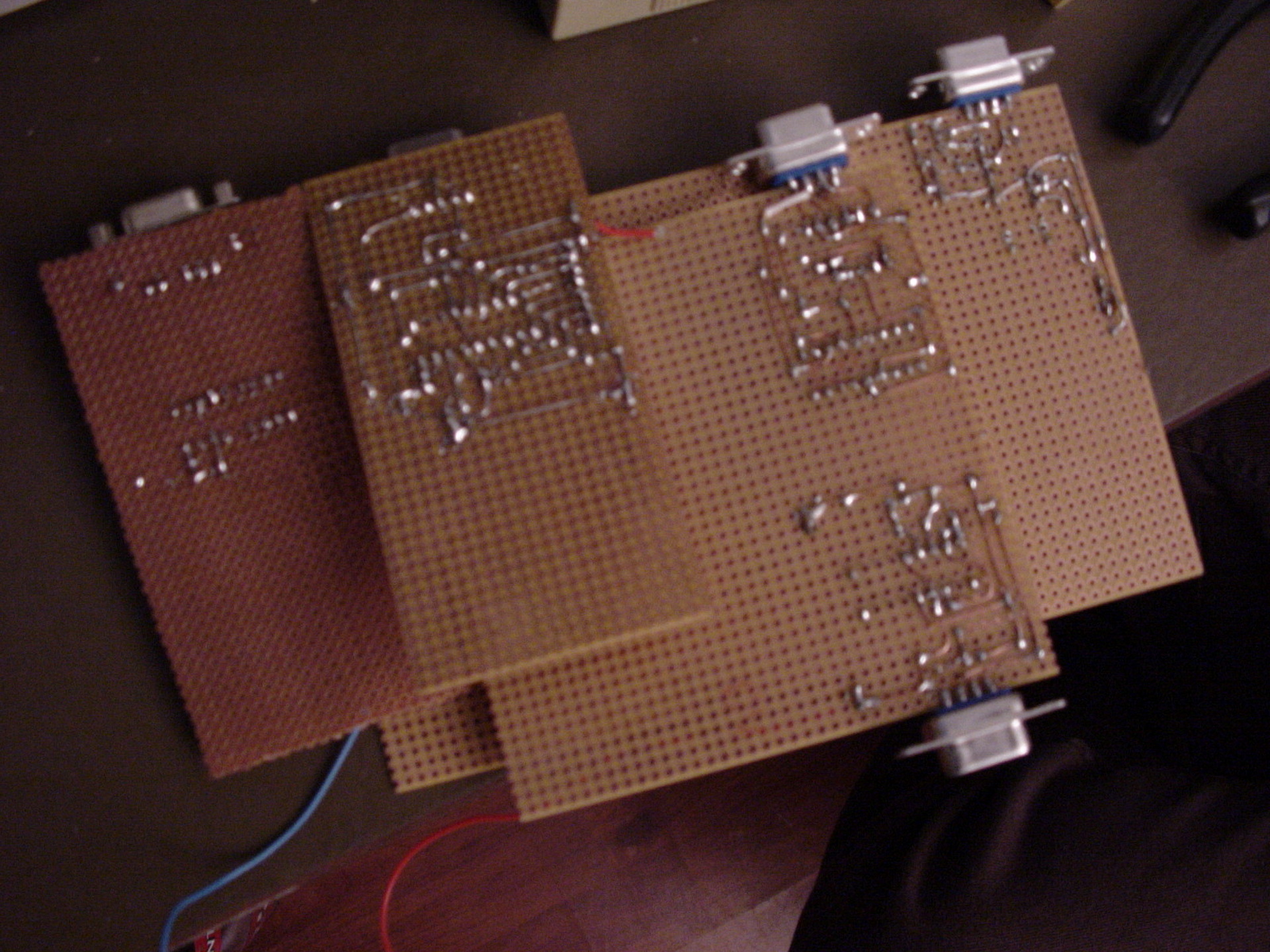
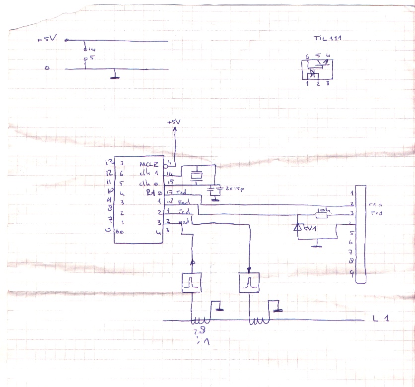
Bigred soldering PIC boards like control units and pic-programmers Below a Infrared receiver (Using Lirc)SchematicPower partPIC Print
One of my schematics
What is this?
=============

 This is the Global Premises Control package. It is intended to be a
complete solution to the DIY home automation. It provides you with a
daemon which will centralize all control functions, and some custom
programs for sound, remote control and things like that.
 The first steps to realizing the goal was made by Koen Martens. He wrote
the first daemon and made the first support programs. Other people got
interested and ported the GPC package to their homes. Since then it seemed
wise to coordinate development to prevent from having three different
versions of the package. It is currently under development and is far from
complete.

History
=======

 15-03-98 - The first initiative
	    With the help of Henri Aanstoot and Marco Geels the first
	    cables were mounted in the ceiling at Waalstraat 136. This
            involved re-dedicating some high voltage lines for the low
	    voltage used by GPC equipment.
	    The next few days Koen Martens spend his time writing software
	    to switch on the lights (which was not possible without
	    software anymore :). This software was very rudimentry and
	    did not feauture the daemon yet.
 28-03-98   Version 1.0 was born.
	    The need for a global way to control the premises arose, and
	    Koen Martens decided to write a daemon which would control the
	    input and output lines, with support programs for the logic.
	    This resulted in global, the gpc daemon.
	    Running on different servers there were programs to control
	    lights and lightswitches (light_control), sound (sound) and
	    the alarm clock (wakeup).
 10-06-98   Version 2.0 (r0.2.0) was born.
	    The support programs containing any logic had vanished,
	    instead the daemon had all the logic encoded in it.
 03-07-98   Version 2.0 still.
	    - Added remote control receiver code.
 29-11-98   GPC r0.3.0
	    - Started coordinated development
 11-12-98   GPC r0.3.1
	    - Security support included, providing a (basic) interface
	      for protecting variables with passwords on a security level
	      clearance basis.
	    - Global notify protocol added, clients can now register one
	      or more variables. This makes the old (0.3.0) polling method
	      obsolete thus reducing the network load dramatically.
	    - Logging library added.

Development
===========

 The development is done on the following beta sites:

 - Subnet
	Location	: Waalstraat 136, Enschede, Netherlands
	Site coordinator: Koen Martens AKA gmc (gmc@freemail.nl)
	Site description: Single floor appartment
			  3 occupants (1 human, 2 rats)
			  P60 32MB RAM running linux
			  486 8MB RAM running FreeBSD
			  486 8MB RAM running linux
			  DEC Writer
			  WYSE terminal
			  The 486 linux machine has the daemon, and is
			  hooked up to the premises.
			  The P60 has a sound card and a RC receiver.
 - Lip-on-ice
	Location	: Lipperkerkstraat 321, Enschede, Netherlands
	Site coordinator: Willem-Jan Faber AKA aloha AKA xtz ( And Henri Aanstoot AKA Fash)
			  (w-jfaber@freemail.nl)
	Site description: Three floor house
			  Four occupants (3 male, 1 female)
			  Connected to three other premises.
			  Computer list not yet in!

 - Venom
	Location	: P. Mondriaanstraat ??, Almelo, Netherlands
	Site coordinator: Sebastiaan Smit AKA venom (wssmit@freemail.nl)
	Site description: Three floor house
			  Three occupants
			  4 computers

 If you would like to join the development, mail me at gmc@freemail.nl.


In progress
===========

 The following projects are in progress right now:
	- A script language to describe the control logic for the daemon
		Koen Martens
	- An cgi interface for the http connectivity
	- Support for sharing variables on multiple daemons

Usage
=====

 Use is for your own risk. We can not be held responsible for any damage
resulted from running any of this software.
 Keeping that in mind, usage is very simple but work needs to be done on
the documentation :)
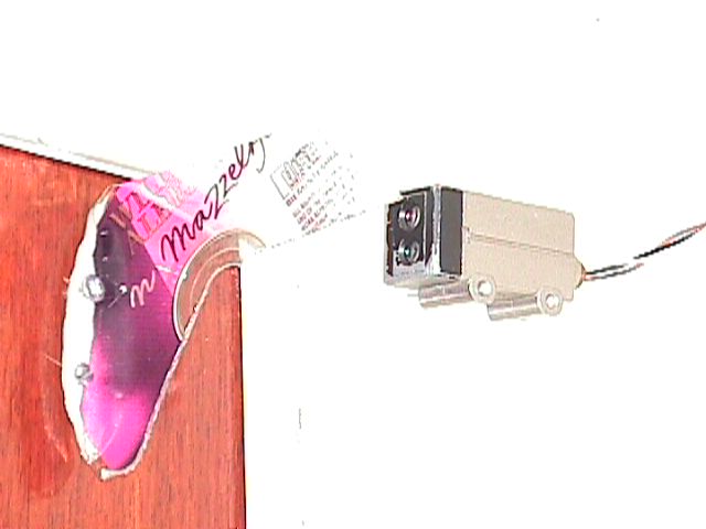
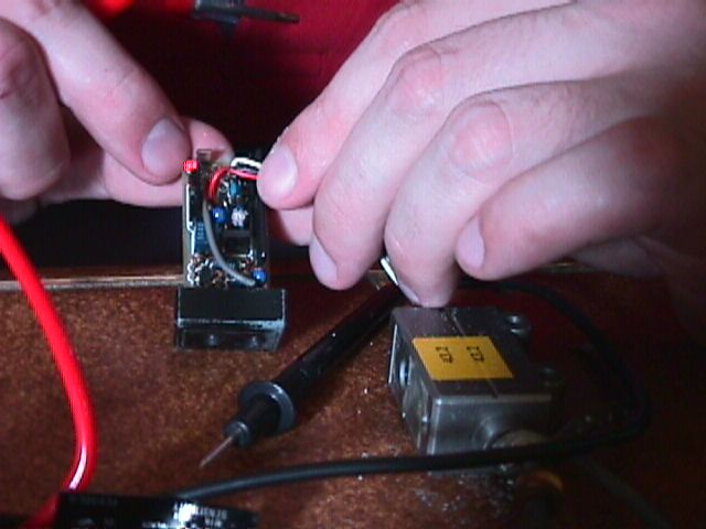
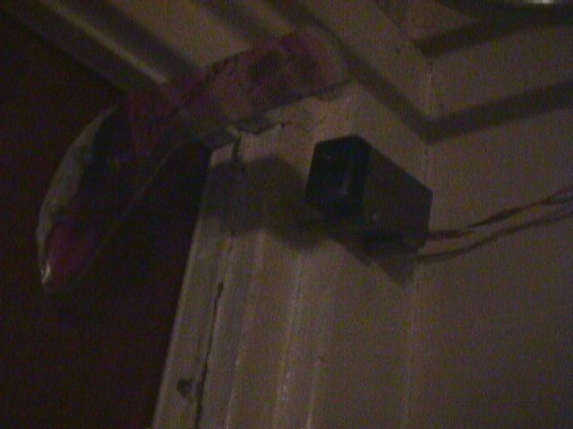
DIY door sensor using a bend CDROM and a sensor i got
I’d would send a signal to our computers and playing a sound sample on our sound system. Also a IRCbot named (lampje) would mention “Backdoor open” in our own channel. (We where running our own IRC servers, interconnected .. because we can. A average of 3 Clients per server sound the way to go .. LOL ) Lampje the IRCbot also controlled the livingroom light and more.
This year i’ve been really into assembly on Intel x86 machines. With EDK we made some demo’s and generally trying to find the limits of the machines we had.
Funny story, edk made a program which changed the palette every scanline (if memory serves me right), while running the program and looking at the screen the colors faded to grayscale. (Something with run-away tables) We look at eachother and said: We must have been using up all colors, we need to refill the graphics card.
I previously made a copperbar alike thingy on a hercules system. (Have not seen them before on a pc back then ) But with below program, i could display pictures which removed the borders.
Below a nsfw video example (pass protected), but a simplified example in pictures below that.
Test image i’ve used on a 320×200 screen resolution
    name split_screen
.286

parm_vert equ 0

data segment
intmsk      db ?
oldvidtab   db 18h dup (?)      ;actuele video-parameters
newvidtab   label byte
            ;HORIZONTAAL
            db 0
            db 12
            db 12
            db 0
            ;VERTIKAAL
            db 0
            db 5
            db 5
            db 0;-40
            ;
            db 0
            db 0
            db 0
            db 0
            db 0
            db 0
            db 0
            db 0
            db 0
            db 0
            db 0
            ;       REGISTER 13H (OFFSET)
            db 0
            ;
            db 18h dup (0)
data ends

stack segment stack
    dw 128 dup (?)
stack ends

code    segment
        assume cs:code,ds:data
cols label byte
set_scrparms:
    mov dx,3d4h
    mov al,11h
    out dx,al
    inc dx
    in al,dx
    and al,7fh  ;clear bit 7: enable writes to vga reg 0..7
    out dx,al
    dec dx
    mov al,13h      ;offset register
    out dx,al
    inc dx
    in al,dx        ;get actual value
    add al,4
    out dx,al
    ret
;
; RE-INIT DISPLAY ROUTINE
;
get_oldvidparms:
    mov dx,3d4h
    mov cx,18h  ;18h registers
    mov di,offset oldvidtab
    mov bl,0    ;begin met register 0
govp1:
    mov al,bl   ;register index
    out dx,al
    inc dx      ;3d5
    in al,dx    ;get actual register content
    dec dx
    mov [di],al
    inc di
    inc bl      ;volgend register
    loop govp1

    mov si,offset oldvidtab
    mov di,offset newvidtab
    mov cx,18h
donewparms:
    mov al,[si]
    add al,[di]
    mov [di],al
    inc si
    inc di
    loop donewparms
    ret
set_newvidparms:
    mov dx,3d4h
    mov cx,18h  ;18h registers
    mov si,offset newvidtab
    mov bl,0    ;begin met register 0
snvp1:
    mov al,bl   ;register index
    out dx,al
    inc dx      ;3d5
    mov al,[si]
    inc si
    out dx,al   ;set register value
    dec dx
    inc bl      ;volgend register
    loop snvp1
    ret

;
; MAIN ENTRY POINT
;
init:
    mov ax,data
    mov ds,ax
    in al,21h
    mov intmsk,al
    cli
    mov al,11111101b
    out 21h,al
    sti
    mov ax,13h
    int 10h
;extend video-memory to 256kb or more
    mov dx,3ceh
    mov al,06h
    out dx,al
    inc dx
    in al,dx
    and al,0f3h
    out dx,al
    ;
    mov ax,0a000h
    mov es,ax
    call set_scrparms
    call get_oldvidparms
    call set_newvidparms
    mov dx,3cch
    in al,dx
    and al,03fh
    mov ah,parm_vert
    ror ah,2
    or al,ah
    mov dx,3c2h
    out dx,al
;
    ;
    push ds
    mov ax,5000h
    mov ds,ax
;
; pallet
;

setpal:
    mov dx,3c8h
    xor al,al
    out dx,al
    inc dx
    mov cx,256*3
    mov si,100h
    cld
    rep outsb
;disp picture routine
    mov ax,6000h
    mov ds,ax
    mov si,0
    mov di,0
    mov ax,0
    mov cx,352*8
    cld
    rep stosw
    mov si,di
    mov cx,8
    cld
    rep stosw
    mov bp,170
    mov si,di
 hiero:
    mov cx,320
    cld
    rep movsb
    mov ax,0
    mov cx,16
    cld
    rep stosw
    mov si,di
    dec bp
    jnz hiero


    xor si,si
    xor di,di
    mov ax,0b000h
    mov es,ax
    mov ax,07000h
    mov ds,ax
    mov cx,3000
    cld
    mov ax,0
    rep stosw
    mov ax,0a000h
    mov es,ax

    mov ax,6000h
    mov ds,ax
    mov di,0
    mov si,di
rhiero:
    push ax
    mov ah,8
    int 21h
    pop ax
    std
    mov cx,-1
    rep movsb


    xor si,si
    xor di,di
    mov ax,0b000h
    mov es,ax
    mov ax,07000h
    mov ds,ax
    mov cx,3000
    cld
    rep movsw
    mov ax,0a000h
    mov es,ax
    pop ds
    ;
mloop:
    mov dx,3dah
wtv1:
    in al,dx
    test al,8
    jnz wtv1
wtv2:
    in al,dx
    test al,8
    jz  wtv2
    mov ah,1
    int 16h
    jz mloop
    xor ah,ah
    int 16h
exit:
    mov ax,3
    int 10h
    cli
    mov al,intmsk
    out 21h,al
    sti
    mov ax,4c00h
    int 21h

code ends
end init
I think i started programming in assembly on PC around 1992. I learned a lot from my friend Edk. Who was a assembly wizard just like Sepp. Reverse engineering routines, writing emulators etc.
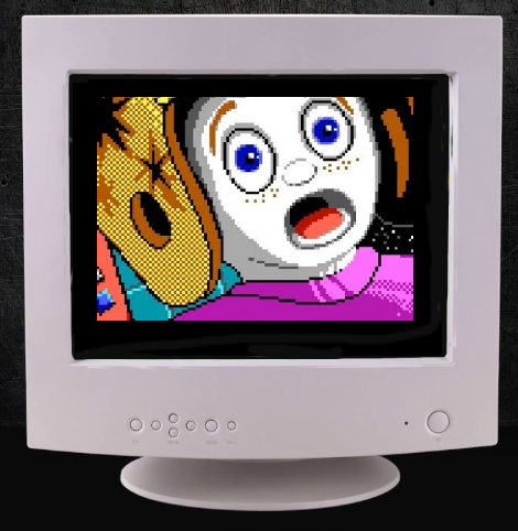
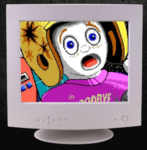
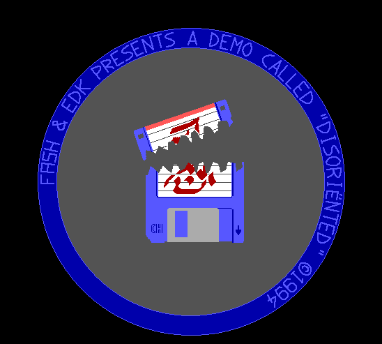
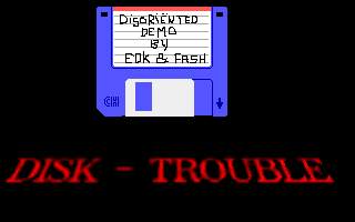
We made several demo’s like the one below. It must have been around 1994.
Dos emulator running our demo from 1994
Just after this one, we started a demo which could run from a 5.25″ boot disk. No dos operating system. When starting your pc, booting from a floppy you would get a starfield, with some text (from a bootsector) ,after that it would load the next sectors, wich contained the rest of the demo. Due to directly programming soundcard and graphics card, this was hard to pull off on different kinds of hardware.
Demo gfx
Example of assembly code for a effect.
    NAME plasma

.model small
.386
.data
colshades   db +001h, 001h,+001h
            db -001h,-001h,-000h
            db +000h,-000h,-001h
            db -000h,-000h,+000h
rgb_cols    db 256*3 dup (?)
cosptr dw 0
sinptr dw 30

.code
demo        proc near

show proc near
    xor di,di
    mov bp,200
show1:
    mov cx,320
    mov si,0
    mov dx,0
show0:
;    push ds
;    mov ax,7000h
;    mov ds,ax
;    lodsb
;    pop ds
    call getsincos
    add cosptr,1
    stosb
    loop show0
;    add dx,1
    add sinptr,1
    dec bp
    jnz show1
    ret
show endp

effect proc near
;   add cosptr,1
;    add sinptr,0
    ret
effect endp

getsincos proc near
    push di
    push ds
    mov si,cosptr
    mov di,sinptr
    mov ax,7000h
    mov ds,ax
    lodsb           ;get cos value
    cmp si,320      ;einde costab?
    jb cosok
    xor si,si
    lodsb
cosok:
    mov ah,al
    xchg si,di
    lodsb           ;get cos value
    cmp si,320      ;einde costab?
    jb sinok
    xor si,si
    lodsb
sinok:
    xchg si,di
    pop ds
    mov cosptr,si
    mov sinptr,di

    mov dx,0
    mov dl,al
    add dl,ah
    adc dh,0
    shr dx,1
    mov al,dl
;    xor al,ah
;    add al,ah
    pop di
    ret
getsincos endp

setcols proc near
    push    es
    push    ds
    pop     es
    mov     di,offset rgb_cols
    mov     si,offset colshades
    mov     dl,0    ;start with black
    mov     bh,0
    mov     bl,0
    mov     bp,4
set_rgball:
    mov     cx,64-1
set_rgb:
    mov     al,dl
    stosb
    mov     al,bh
    stosb
    mov     al,bl
    stosb
    mov     al,[si]
    add     dl,al
    mov     al,[si+1]
    add     bh,al
    mov     al,[si+2]
    add     bl,al
    loop    set_rgb
    add     si,3
    dec     bp
    jnz     set_rgball
    pop     es
    ret
setcols endp

setrgb proc near
    mov dx,3c8h
    xor al,al       ;start with colour 00h
    out dx,al
    inc dx
    mov si,offset rgb_cols
    mov cx,256*3
    rep outsb       ;set 256 RGB values
    ret
setrgb endp

wvtr proc near
    mov dx,3dah
wtv:
    in al,dx
    test al,8
    jz wtv
    ret
wvtr endp

start:
    cld
    mov ax,@data
    mov ds,ax
    mov ax,0a000h
    mov es,ax
    mov ax,13h
    int 10h         ;screen 320x200 256 colours
    call setcols
    call setrgb
    call show
    mov al,11111101b
    out 21h,al      ;disable int
mloop:
    call wvtr
;    call show
    call effect
    mov ah,1
    int 16h
    jz mloop
    xor ah,ah
    int 16h
exit:
    xor al,al
    out 21h,al      ;enable int
    mov ax,3
    int 10h         ;screen  80x25 text
    mov ax,4c00h
    int 21h         ;back to DOS
demo        endp

end start
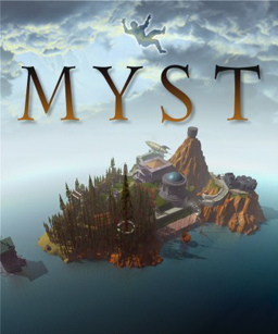
Around 1993 i bought Myst, a adventure game. It was really a masterpiece, a interactive rendered world with great moodsetting music scores.
When looking at documentaries like these: https://www.youtube.com/watch?v=EWX5B6cD4_4 It almost didn’t happen, i was oblivious to this fact ..
Many hours i spent playing this game, sometimes together with Erik.
I loved the puzzles and the rendered transitional movies.
After the first i bought all follow-ups.
I spend hours playing them, first with Erik and later with Monique and Coline taking turns at the controls. Solving the mysteries together was a lot of fun.
1993 – Myst
1997 – Riven
2001 – Myst III: Exile
2003 – URU: Ages Beyond Myst
2004 – Myst IV: Revelation
2005 – Myst V: End of Ages
There is also a parody version called Pyst
After that i found realmyst a remake of the first with better graphics. We played Uru: Ages beyond myst or Uru Live after that. This one had free movement i recall.
I wanted to create a point and click/walk around version myself. My first idea was taking pictures in my fathers car driving from Holten to Laren where Martin lived. Taking pictures (with a analog camera) on the way. Scanning those analog pictures and making a point and click thingy was something i only realized many years later.
I made a website with pictures of the house. People could click and move though my house. I made the path which was obvious in advance, when people clicked a new area or object, they got a popup where you could request the path or object information.
(i found the source code – now i have to make a webserver with a really old php version to get screenshots)
I never came around it to render environments myself .. see my post about rendering.
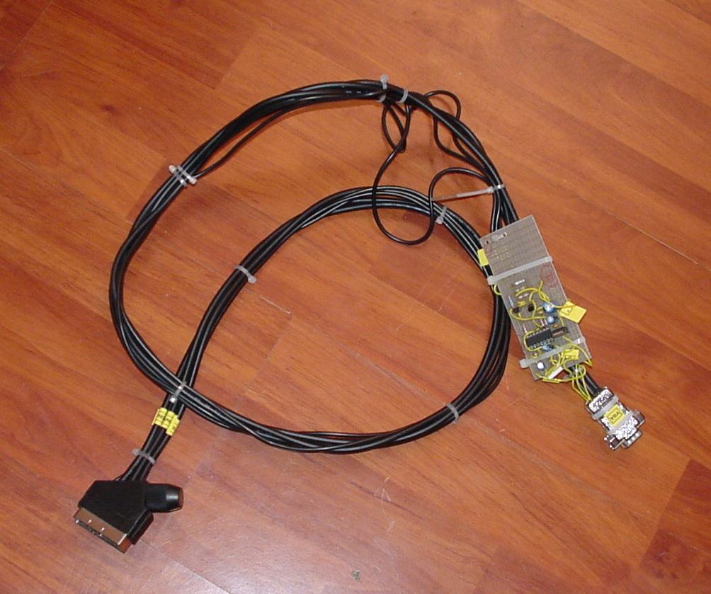
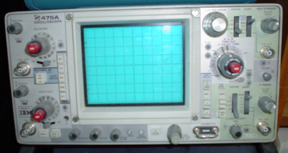
Somewhere in 1992 i got hold of a Oscilloscope, probably borrowed from someone. I don’t know what happend to it. I got the idea to generate drawings on the scope, because it had two inputs with you could switch to x and y inputs.
Example oscilloscope
My friend Sepp got into it also, we both wrote some software to do funky stuff with this. I found some software today (20220516), and having bought a old skool scope 2 years ago …
So i found source machine code, no executables. Now i needed to get a assembler running again.
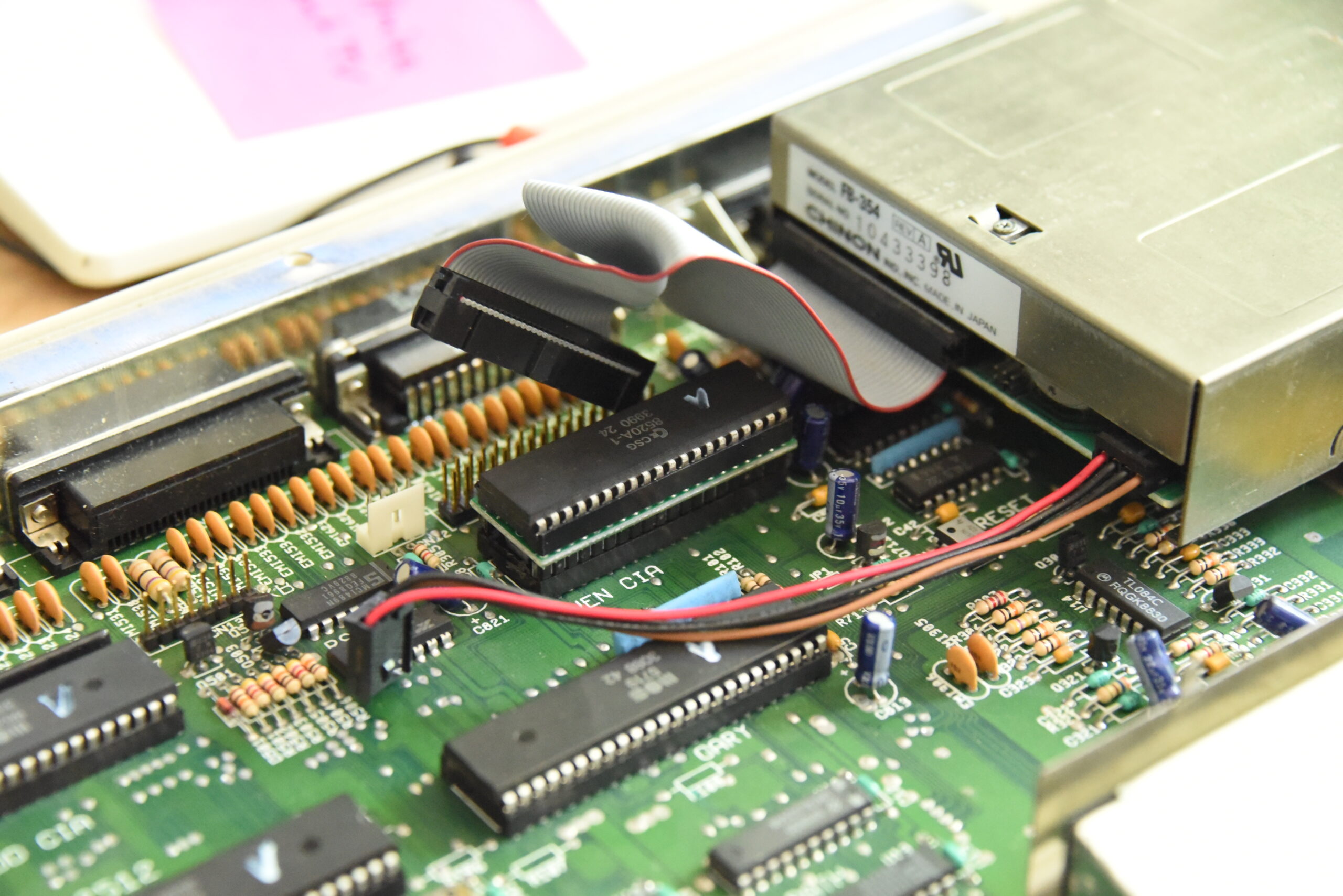
Sidenote: I recently fixed a Amiga 500 and got a disk switch installed on the even cia.
Disk df0 df1 switch print at the center of the image
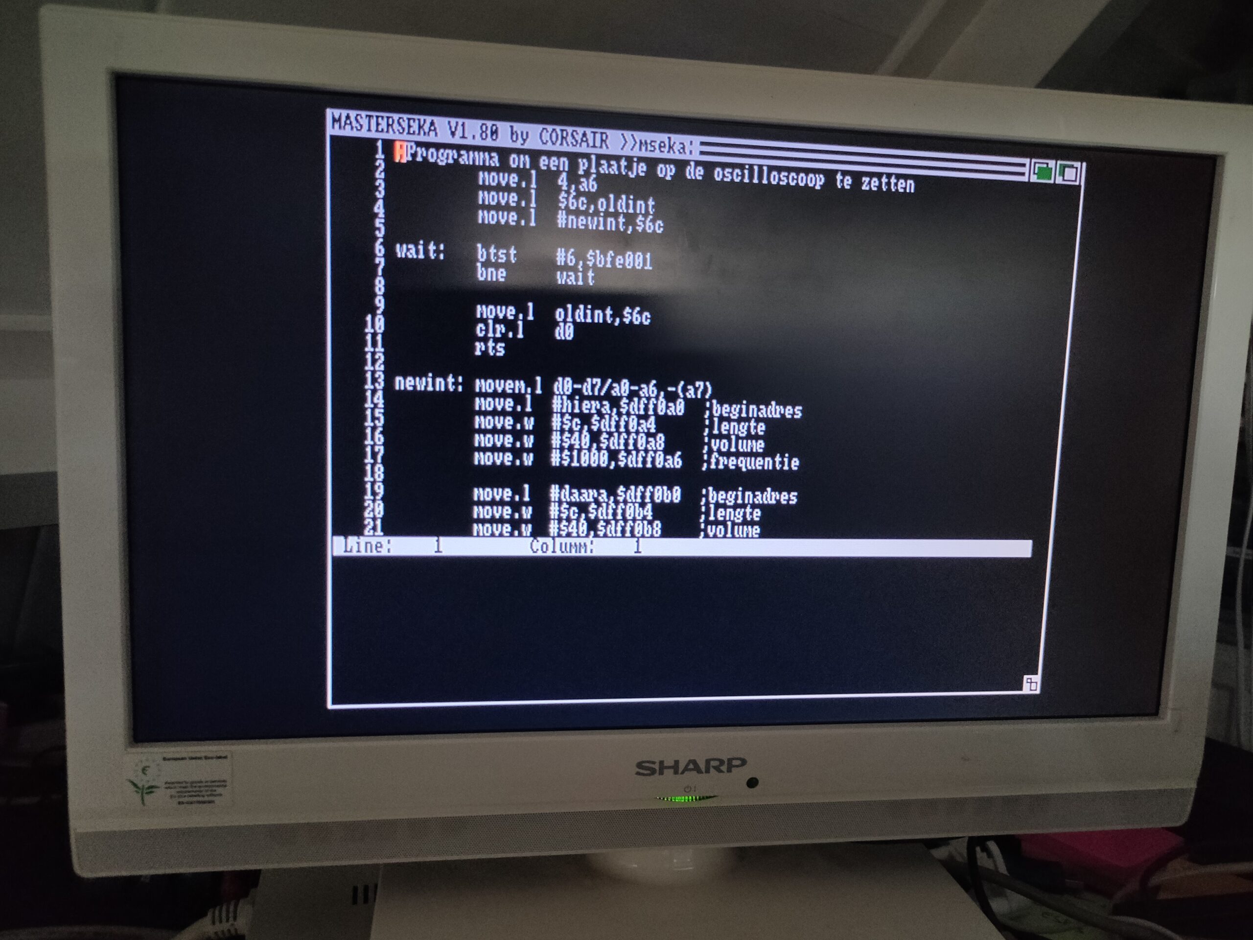
Booting some old seka disks and starting MasterSeka again in a looong time.
ESC - open editor
r (read file)
v (directory)
a + enter + enter (no options assemble)
g (go running the program)
FIrst part of machine code .. at the bottom part are arrays of coordinates to draw things
Some programs on the disk: (some are made by Sepp, who is a far better coder than i am)
Funny triangles
Lissajous figures
Moving square
House
House with door
Draw with mouse
Lissajous figures are simple sine and cosine functions to get:
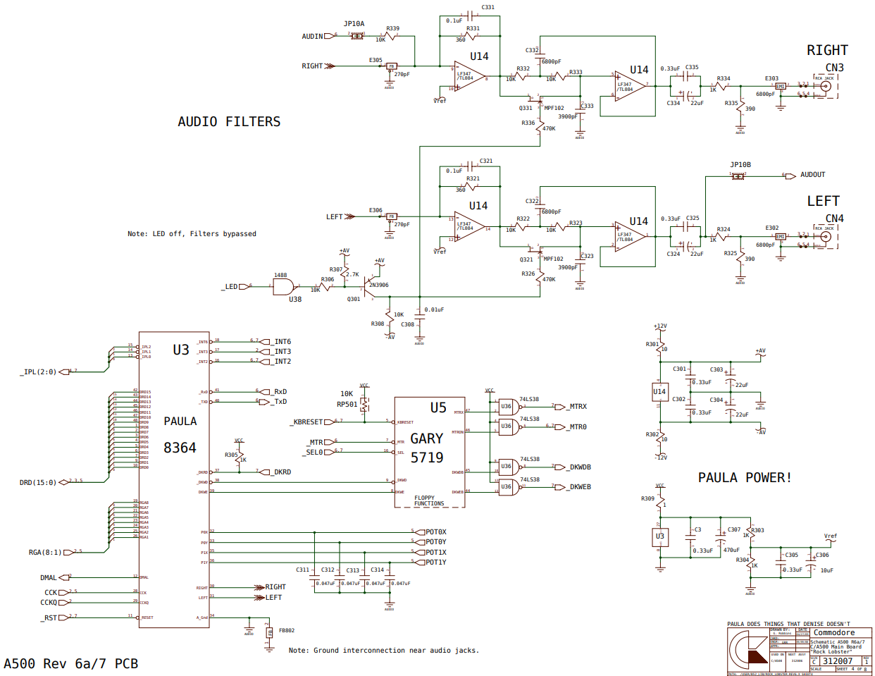
So how does this work, well a amiga has stereo outputs. These are controlled by two DAC outputs on the 8364 (Paula) chip. (DAC – Digital Analog Convertor) ( Paula has 4 DMA controlled DACs !! )
Looking at the schematics of the audio part, we see a lot going on concering audio filters. The tests i’ve done today (2022) are on a amiga with unmodified audio filters. (Low on my prio list) So frequencies are not direct what you get directly converted from digital values. Besides that, syncronisation between left and right channel, even using DMA can be an issue. (DMA – Direct Memory Access, this means that it can be controlled without using the CPU)
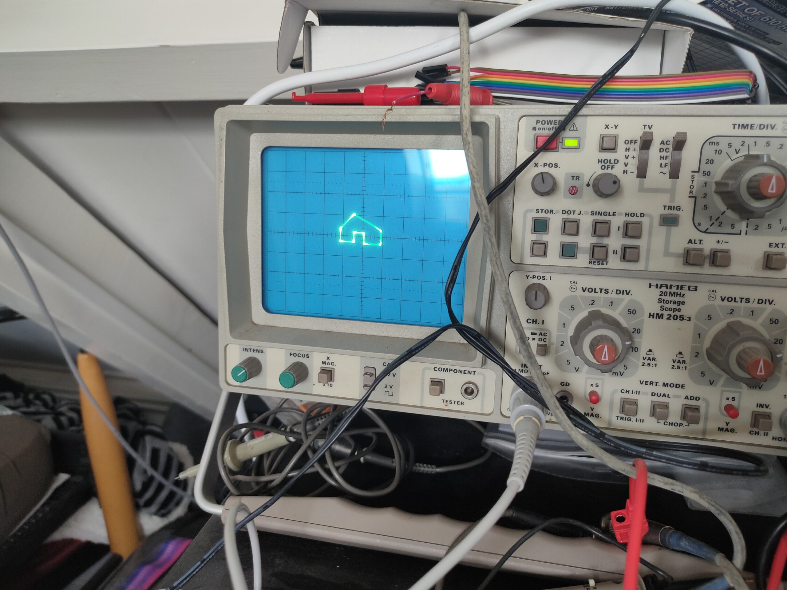
Running the house draw code:
A little house
Note: Due to different hardware not a good working example .. yet
More examples .. hard to capture a still image
I tried a few years after we did this, to modify a generic monitor to display things using two inputs, not using scanlines. But to no avail. Only flipping the screen and colors using relais (more on this later)
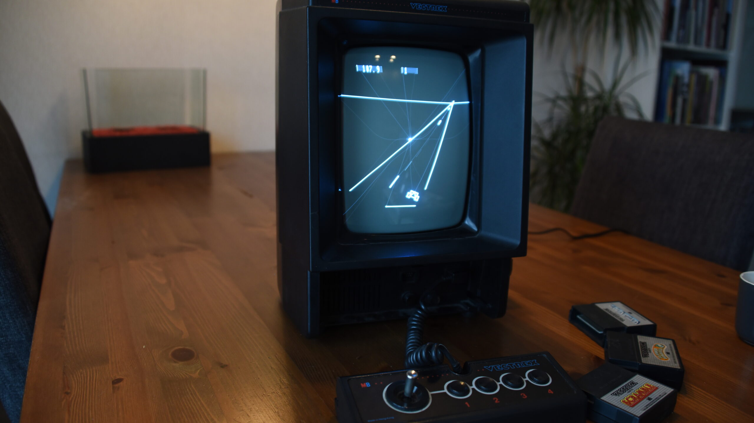
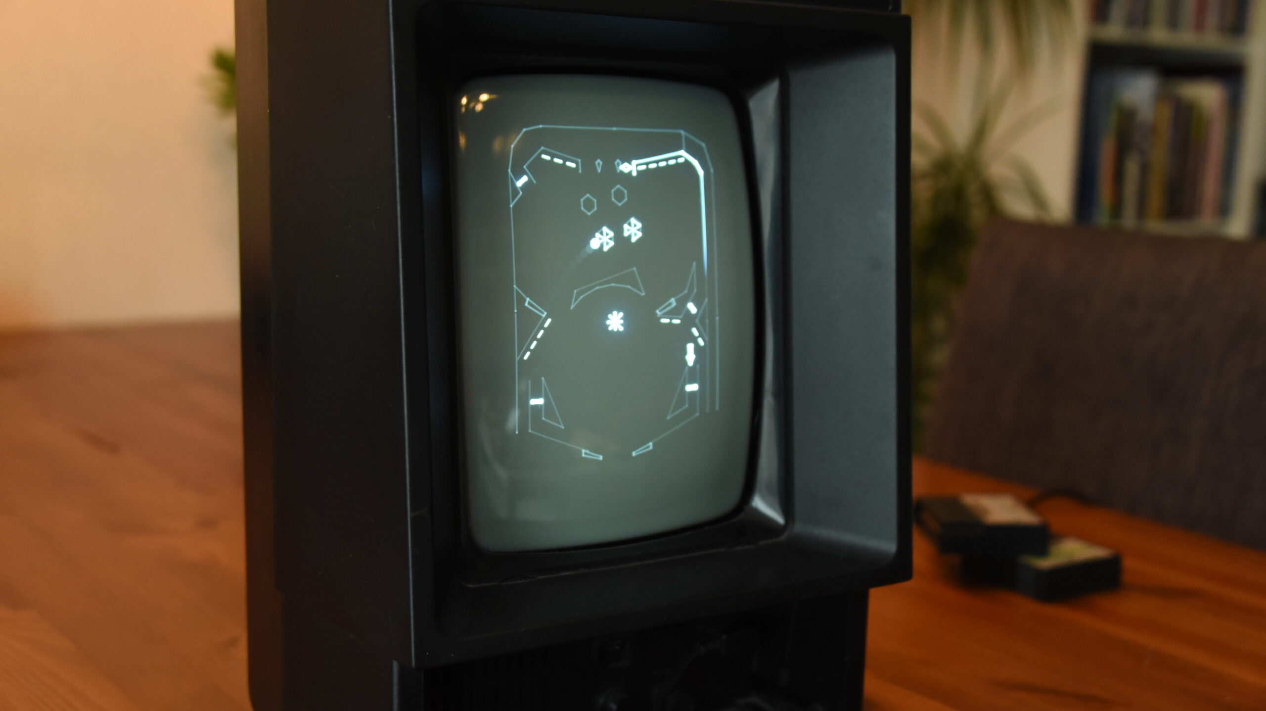
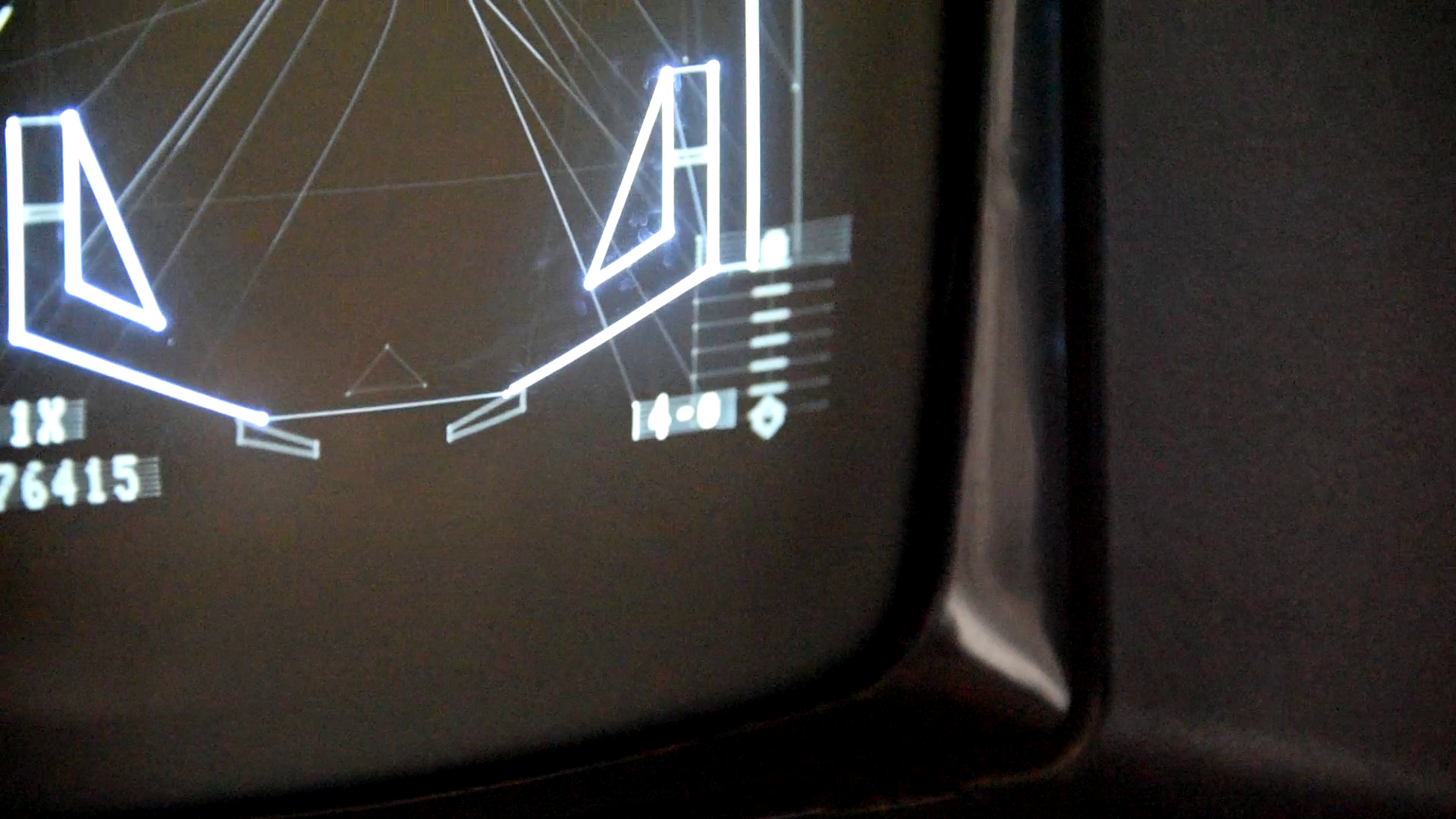
Bonus part: Above did remind me of a Vectrex, a game console which utilises same display technic. So no raster lines and pixels, but line drawing by controlling the beam.
Two games on a borrowed Vectrex – You can see the continuous line – faint to see, even harder IRLMovie from 2017 .. Vectrex was made in 1982-1983
"If something is worth doing, it's worth overdoing."