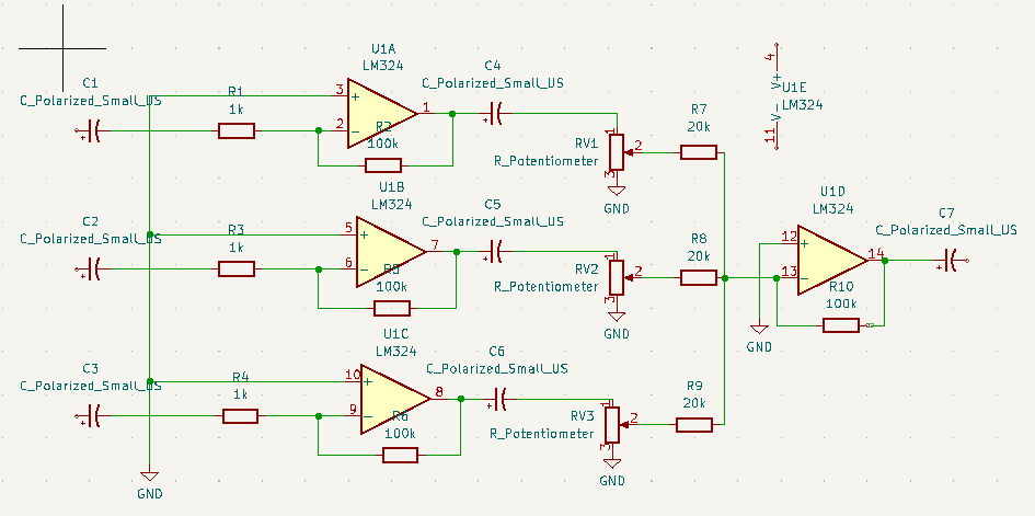
At the back the 8 pin single channel lm368 amplifier. At the front the 3 channel setup. I still have to tweak the resistors, and potmeters. Then I can make a permanent PCB, and figure out the connections to the 6502.
At the moment, the Arduino Nano is playing some real sound samples by using the registers of the sound chip. The music is being played by sending the register dumps directly to the chip.
Much like i’ve been using SID register dumps to play songs in another project.
This is version 0.1 .. do not use. If its wrong, or can do better please mail me. Oh it needs a 1k resistor from the 20K’s to ground I think.
I’ve posted in the past something about pl/m. Today i got this running again in a dosbox.
The PL/M programming language (an acronym of Programming Language for Microcomputers) is a high-level language conceived and developed by Gary Kildall in 1973 for Intel’s microprocessors.
PLM86 PROGRAM.PLM
LINK86 PROGRAM.OBJ, PLM\DOSLIBS.LIB, PLM\UTILS.LIB TO %1.LNK INITCODE
LINK PROGRAM.LNK;;;
Tic Tac Toe in PLM
bke:do;
/*DOEL:                                              */
/*Dit programma is boter kaas en eieren voor twee    */
/*spelers, er wordt gecontroleerd of iemand gewonnen */
/*heeft. (Je speelt niet tegen de computer)          */
/*UPDATE:12/2/90,15/2/90,18/2/90  RELDATE:19/2/90    */
/*PROGRAMMER:H.M.Aanstoot                            */
/*UPDATE 5/3/90 1:13:23                              */
/*De volgende 4 regels zorgen ervoor dat de compiler */
/*de PLM  DOS,UTIL routines die op disk staan        */
/*meestuurt naar de linker                           */
/* bla bla 2de versie met STRINGS!! eindelijk gelukt */

$include(plm\doslibs.inc)
$include(plm\doslibs.dcl)
$include(plm\utils.dcl)
dcl naam(3)           pointer;
dcl plaats(9)         word;
dcl teken(2)          pointer;
dcl aanzet            word;
dcl loop              word;
dcl a                 word;
dcl winnaar           word;
dcl nummer            word;
dcl item              word;
dcl error_status      word;

spelerzet:procedure;
call dsso(naam(aanzet));
call dsso(@(', geef een getal: $'));
invoer:
nummer=dsin;
nummer=nummer-48;
if nummer<1 or nummer>9 then goto invoer;
if plaats(nummer)<>0 then goto invoer;
call dso(nummer+48);
plaats(nummer)=aanzet;
end spelerzet;

update:procedure;
item=1;
call dsso(@(cr,lf,'+-----+-----+-----+',cr,lf,eos));
call dsso(@('|     |     |     |',cr,lf,eos));
call dso(124);call zet;call dso(124);call zet;call dso(124);call zet;
 call dsso(@(124,cr,lf,eos));
call dsso(@('|     |     |     |',cr,lf,eos));
call dsso(@('+-----+-----+-----+',cr,lf,eos));
call dsso(@('|     |     |     |',cr,lf,eos));
call dso(124);call zet;call dso(124);call zet;call dso(124);call zet;
 call dsso(@(124,cr,lf,eos));
call dsso(@('|     |     |     |',cr,lf,eos));
call dsso(@('+-----+-----+-----+',cr,lf,eos));
call dsso(@('|     |     |     |',cr,lf,eos));
call dso(124);call zet;call dso(124);call zet;call dso(124);call zet;
 call dsso(@(124,cr,lf,eos));
call dsso(@('|     |     |     |',cr,lf,eos));
call dsso(@('+-----+-----+-----+',cr,lf,eos));

  call dsso(@('    1   2   3',cr,lf,eos));
  call dsso(@('    4   5   6',cr,lf,eos));
  call dsso(@('    7   8   9',cr,lf,eos));
end update;


zet:procedure;
if plaats(item)=0 then call dsso(@('     $'));
if plaats(item)=1 then call dsso(@('  X  $'));
if plaats(item)=2 then call dsso(@('  O  $'));
item=item+1;
end zet;

check:procedure;
   do a=1 to 2;
   if plaats(1)=a and plaats(2)=a and plaats(3)=a then winnaar=a;
   if plaats(4)=a and plaats(5)=a and plaats(6)=a then winnaar=a;
   if plaats(7)=a and plaats(8)=a and plaats(9)=a then winnaar=a;

   if plaats(1)=a and plaats(4)=a and plaats(7)=a then winnaar=a;
   if plaats(2)=a and plaats(5)=a and plaats(8)=a then winnaar=a;
   if plaats(3)=a and plaats(6)=a and plaats(9)=a then winnaar=a;

   if plaats(1)=a and plaats(5)=a and plaats(9)=a then winnaar=a;
   if plaats(3)=a and plaats(5)=a and plaats(7)=a then winnaar=a;
   end;
end check;


hoofdprogramma:
winnaar=3;
naam(1)=@('Speler 1$');
naam(2)=@('Speler 2$');
naam(3)=@('Niemand$');
do a=1 to 9; plaats(a)=0; end;
teken(1)=@('kruisje$');
teken(2)=@('rondje$');
aanzet=1;

    do loop=1 to 9;
    call update;
    call check;
    if winnaar<>3 then goto gewonnen;
    call spelerzet;
    aanzet=3-aanzet;
    end;

call update;
gewonnen:
call dsso(naam(winnaar));
call dsso(@(' heeft gewonnen',cr,lf,eos));
if winnaar=3 then call dsso(@('Helaas, pindakaas!$'));
			 else call dsso(@('Gefeliciteerd ermee!$'));

call dexit(error_status);
end;
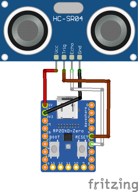
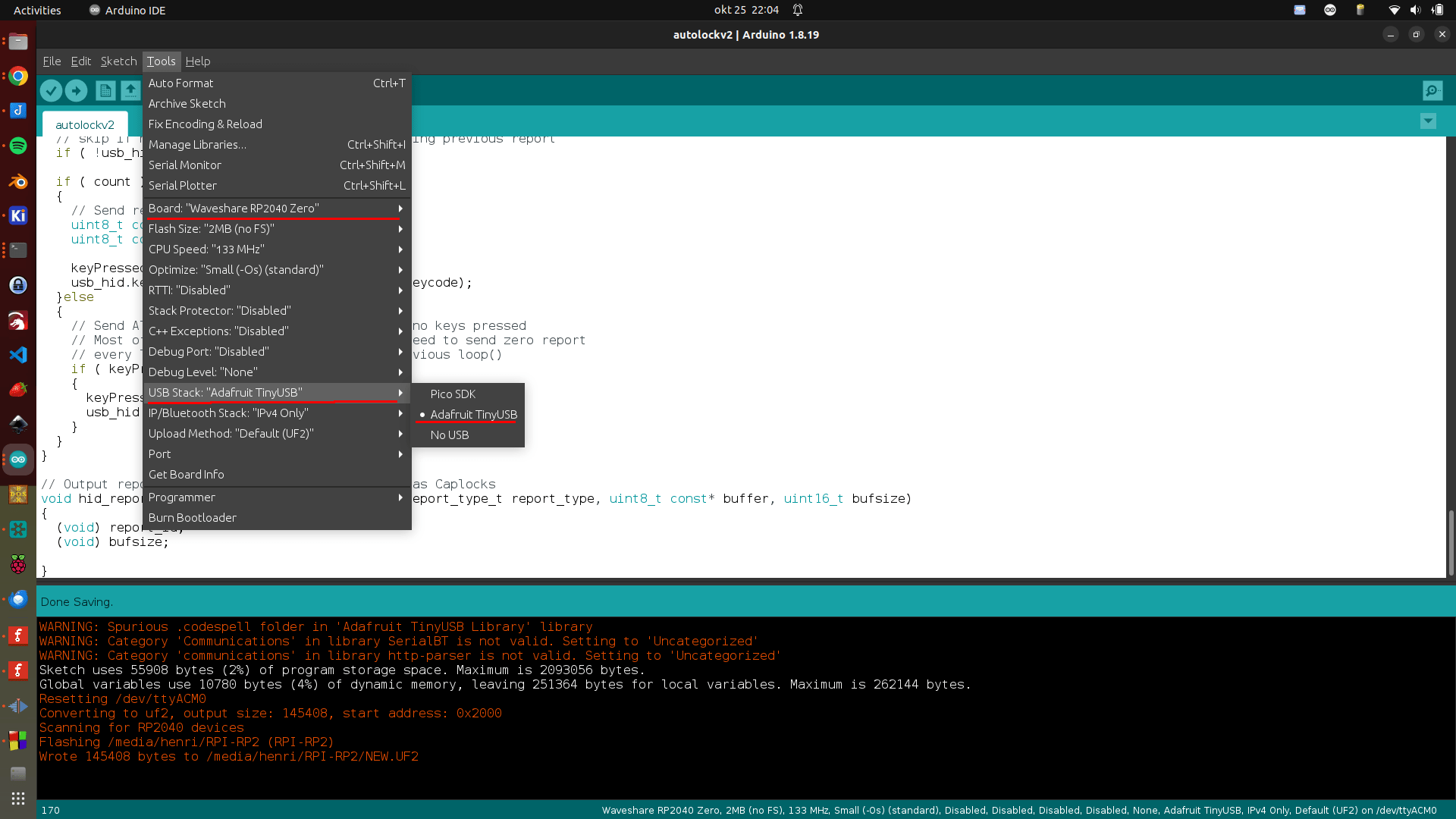
Point the sensor at yourself when behind your computer. When you leave your computer for some seconds, it wil automatically lock your screen. (Windows-L keypress) The RP2040 is configured as HID so it emulates a keyboard. Just connect via an usb-cable to your machine
#include "Adafruit_TinyUSB.h"
// defines pins numbers
const int trigPin = D4;
const int echoPin = D5;
// defines variables
long duration;
int distance;
int maxcounter;
uint8_t const desc_hid_report[] =
{
  TUD_HID_REPORT_DESC_KEYBOARD()
};

// D0-D3 NOT USED AT THE MOMENT, I'VE GOT IDEAS FOR EXTRA FUNCTIONALLITY!

// USB HID object. For ESP32 these values cannot be changed after this declaration
// desc report, desc len, protocol, interval, use out endpoint
Adafruit_USBD_HID usb_hid(desc_hid_report, sizeof(desc_hid_report), HID_ITF_PROTOCOL_KEYBOARD, 2, false);

//------------- Input Pins -------------//
// Array of pins and its keycode.
  uint8_t pins[] = { D0, D1, D2, D3 };


// number of pins
uint8_t pincount = sizeof(pins)/sizeof(pins[0]);

// For keycode definition check out https://github.com/hathach/tinyusb/blob/master/src/class/hid/hid.h
uint8_t hidcode[] = { HID_KEY_0, HID_KEY_1, HID_KEY_2, HID_KEY_3 , HID_KEY_4, HID_KEY_5 };

#if defined(ARDUINO_SAMD_CIRCUITPLAYGROUND_EXPRESS) || defined(ARDUINO_NRF52840_CIRCUITPLAY) || defined(ARDUINO_FUNHOUSE_ESP32S2)
  bool activeState = true;
#else
  bool activeState = false;
#endif

void setup()
{
  // Setting pins for Ultrasonic Sensor HC-SR04
  pinMode(trigPin, OUTPUT); // Sets the trigPin as an Output
  pinMode(echoPin, INPUT); // Sets the echoPin as an Input

#if defined(ARDUINO_ARCH_MBED) && defined(ARDUINO_ARCH_RP2040)
  // Manual begin() is required on core without built-in support for TinyUSB such as mbed rp2040
  TinyUSB_Device_Init(0);
#endif

  // Set up output report (on control endpoint) for Capslock indicator
  // Not used .. yet
  usb_hid.setReportCallback(NULL, hid_report_callback);

  usb_hid.begin();

  // overwrite input pin with PIN_BUTTONx
  // NOT USED
#ifdef PIN_BUTTON1
  pins[0] = PIN_BUTTON1;
#endif

#ifdef PIN_BUTTON2
  pins[1] = PIN_BUTTON2;
#endif

#ifdef PIN_BUTTON3
  pins[2] = PIN_BUTTON3;
#endif

#ifdef PIN_BUTTON4
  pins[3] = PIN_BUTTON4;
#endif

  // Set up pin as input
  for (uint8_t i=0; i<pincount; i++)
  {
    pinMode(pins[i], activeState ? INPUT_PULLDOWN : INPUT_PULLUP);
  }

  // wait until device mounted
  while( !TinyUSBDevice.mounted() ) delay(1);

maxcounter =0;
}

void loop()
{

  // Clears the trigPin
  digitalWrite(trigPin, LOW);
  delayMicroseconds(2);
  // Sets the trigPin on HIGH state for 10 micro seconds
  digitalWrite(trigPin, HIGH);
  delayMicroseconds(10);
  digitalWrite(trigPin, LOW);
  // Reads the echoPin, returns the sound wave travel time in microseconds
  duration = pulseIn(echoPin, HIGH);
  // Calculating the distance
  distance = duration * 0.034 / 2;
  // Prints the distance on the Serial Monitor - DEBUG
  //Serial.print("Distance: ");
  //Serial.println(distance);

  // Below will wait for more than 100 measurements with a distance of 100
  // Then it will send a WINDOWS-L (lock) keyboard combination
  if (distance > 100)
  {
    maxcounter +=1;
  }
  else
  {
    maxcounter = 0;
  }
  if (maxcounter > 100 && maxcounter < 150)
  {
    maxcounter = 200;
       // Send report if there is key pressed
    uint8_t const report_id = 0;


    uint8_t  modifier = KEYBOARD_MODIFIER_LEFTGUI;
          uint8_t keycode[6] = { 0 };
      keycode[0] = HID_KEY_L;


    usb_hid.keyboardReport(report_id, modifier, keycode);
    delay(10);
    // Un-press keys :)
    usb_hid.keyboardRelease(0);

  }


  // poll gpio once each 2 ms
  delay(20);

  // used to avoid send multiple consecutive zero report for keyboard
  static bool keyPressedPreviously = false;

  uint8_t count=0;
  uint8_t keycode[6] = { 0 };

  // scan normal key and send report
  for(uint8_t i=0; i < pincount; i++)
  {
    if ( activeState == digitalRead(pins[i]) )
    {
      // if pin is active (low), add its hid code to key report
      keycode[count++] = hidcode[i];

      // 6 is max keycode per report
      if (count == 6) break;
    }
  }

  if ( TinyUSBDevice.suspended() && count )
  {
    // Wake up host if we are in suspend mode
    // and REMOTE_WAKEUP feature is enabled by host
    TinyUSBDevice.remoteWakeup();
  }

  // skip if hid is not ready e.g still transferring previous report
  if ( !usb_hid.ready() ) return;

  if ( count )
  {
    // Send report if there is key pressed
    uint8_t const report_id = 0;
    uint8_t const modifier = 0;

    keyPressedPreviously = true;
    usb_hid.keyboardReport(report_id, modifier, keycode);
  }else
  {
    // Send All-zero report to indicate there is no keys pressed
    // Most of the time, it is, though we don't need to send zero report
    // every loop(), only a key is pressed in previous loop()
    if ( keyPressedPreviously )
    {
      keyPressedPreviously = false;
      usb_hid.keyboardRelease(0);
    }
  }
}

// Output report callback for LED indicator such as Caplocks
void hid_report_callback(uint8_t report_id, hid_report_type_t report_type, uint8_t const* buffer, uint16_t bufsize)
{
  (void) report_id;
  (void) bufsize;

}
It’s a long time i’ve made a PLC ladder, but lets see how and what this integration brings me.
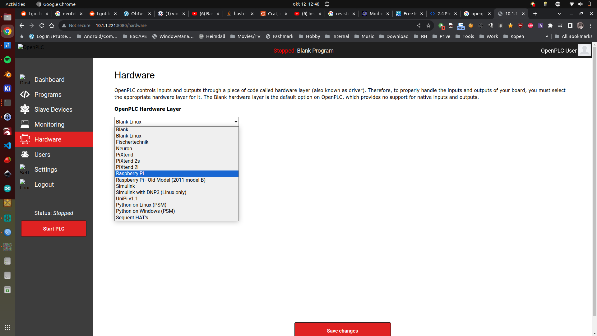
OpenPLC interface on a Raspberry, I could not start a program on RPI 5! But it compiled correctly. See below rpi3
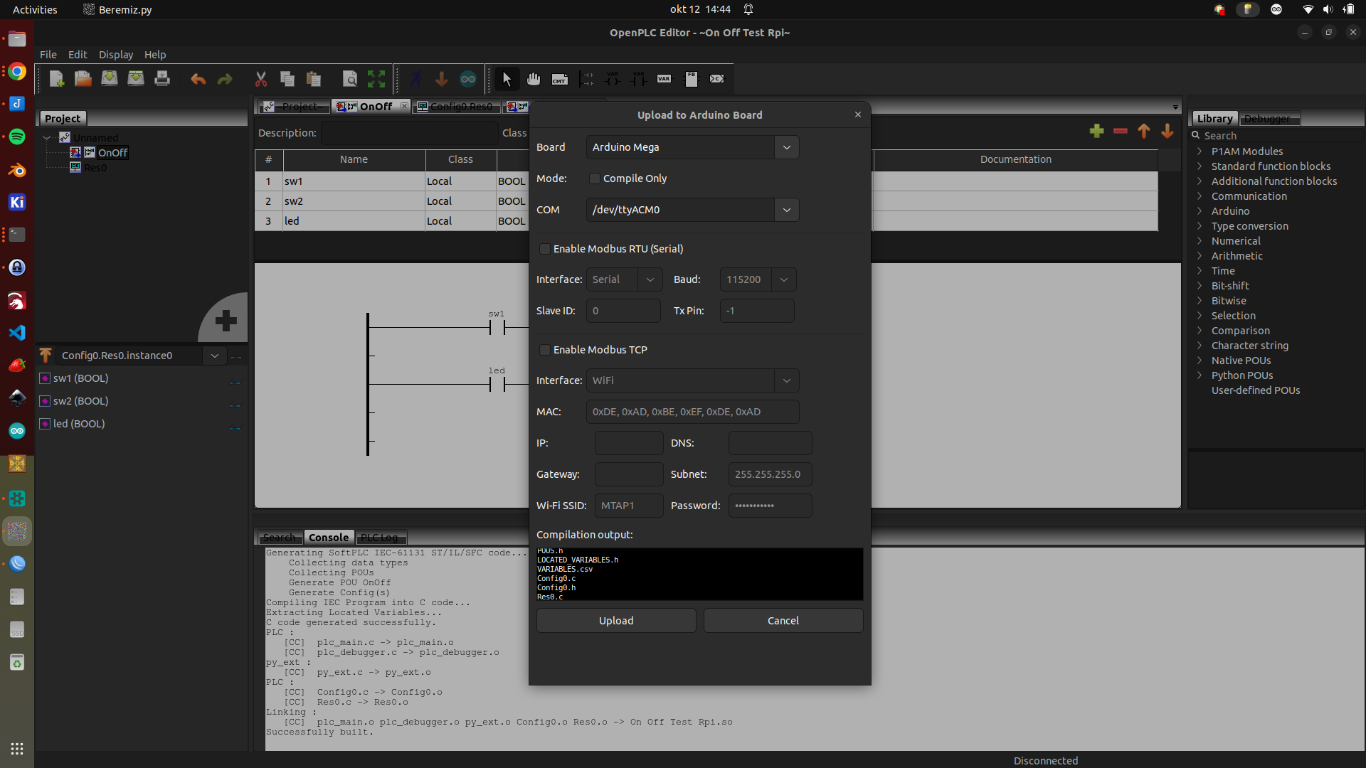
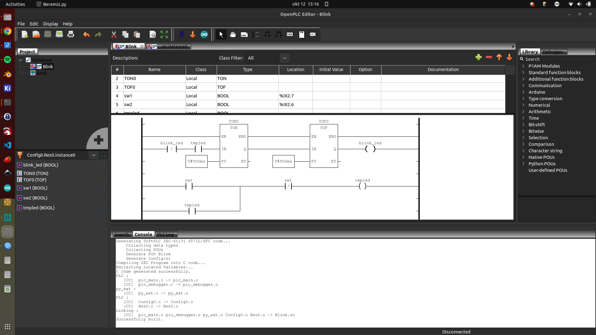
OpenPLC editor with timer ladders for Arduino
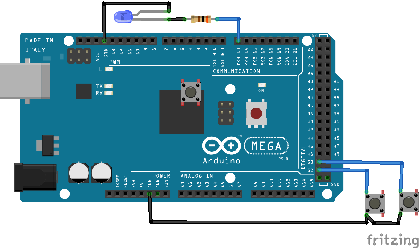
Schematic with a led and two buttons (and one floating in the middel, which i forgot to remove)
Working example ( wemos and display are from another project those are not connected )
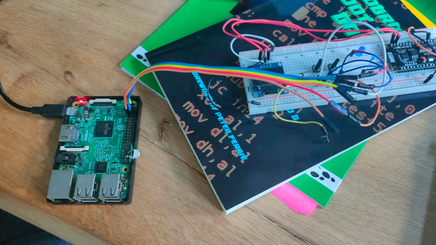
UPDATE 20231015 – Raspberry 3 with OpenPLC
GND to leds and buttons GPIO2 (pin 3) to a button GPIO3 (pin 5) to another button GPIO14 (pin 8) to the led
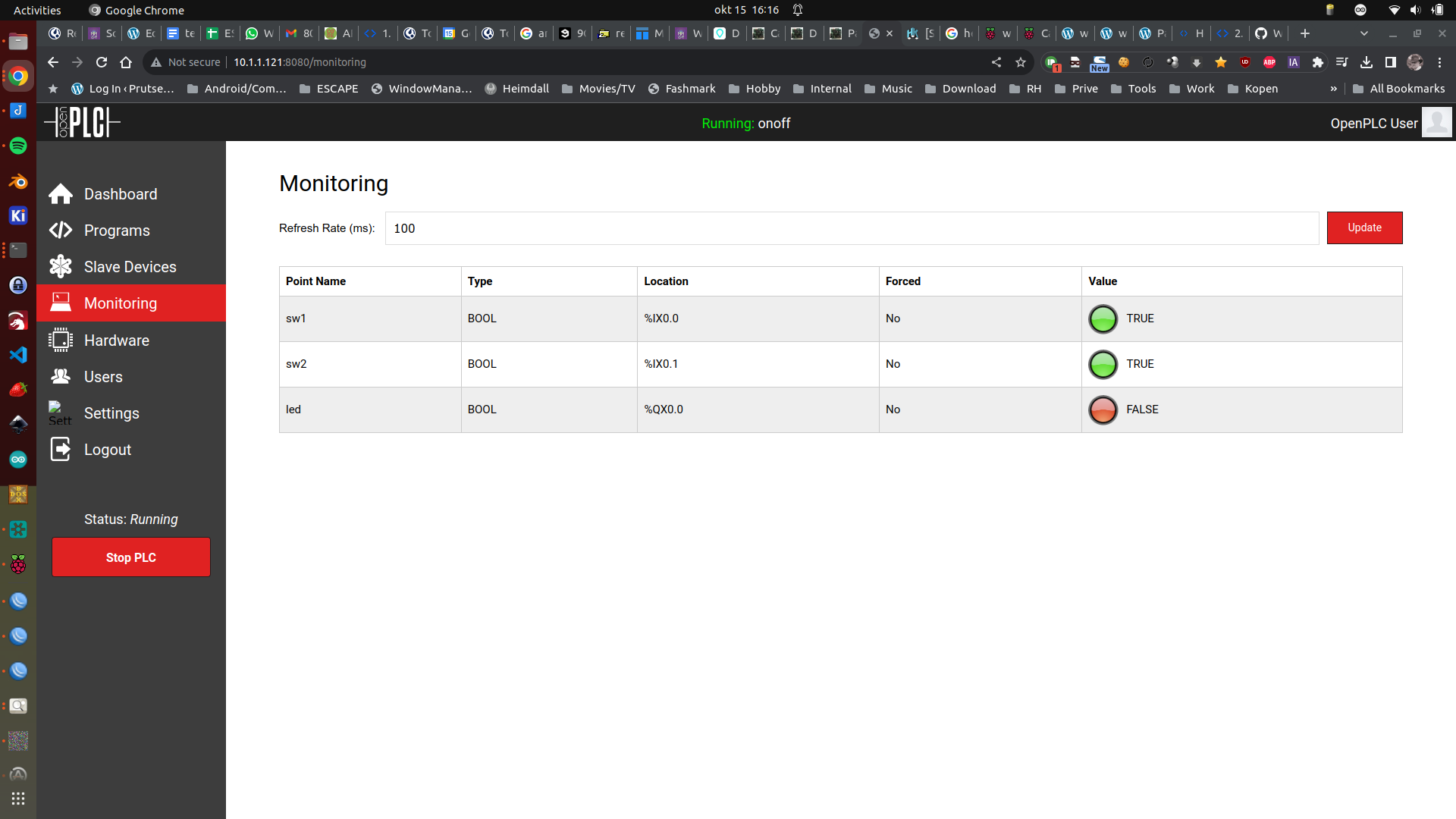
Now OpenPLC works correct (RPI3)
https://github.com/thiagoralves/OpenPLC_v3.git
cd OpenPLC_v3
./install.sh rpi

## Warning .. takes a really long time

Wiringpi is deprecated
But can be installed using the last git repo

git clone https://github.com/WiringPi/WiringPi.git
cd WiringPi
./build
(NOTE, Dosbox can’t cope with the register speed, use real HW or PCem)
Effect using a edited photo I made from fireworks ..
Generating a RAW image and Palette, a in a new way
This bash script to convert BMP to Raw and a compiled colorpalette. (Note: this converts to 8 bit depth, the assembly code in the final assemby program converts to 6 for VGA mode 13h
So this time, i won´t have to use the standard VGA palette as mentioned in previous posts. (Gimp colors > indexed (255 colors) ; save as BMP, exclude colorspace information)
I’m using identify to extract the colorpalette, which i’m converting to DB entries for the fasm compiler
3C8h (R/W):  DAC Address Write Mode
 bit 0-7  The color data register (0..255) to be written to 3C9h.
 Note: After writing the 3 bytes at 3C9h this register will increment, pointing to the next data register.

3C9h (R/W):  DAC Data Register
 bit 0-8?  Color value
 Note:  Each read or write of this register will cycle through first the
        registers for Red, Blue and Green, then increment the appropriate
        address register, thus the entire palette can be loaded by writing 0 to
        the DAC Address Write Mode register 3C8h and then writing all 768 bytes
        of the palette to this register.

3DAh
Input Status #1 Register (Read at 3BAh (mono) or 3DAh (color))
7	6	5	4	3	2	1	0
                            VRetrace			DD

VRetrace -- Vertical Retrace
"When set to 1, this bit indicates that the display is in a vertical retrace interval.This bit can be programmed, through the Vertical Retrace End register, to generate an interrupt at the start of the vertical retrace."
DD -- Display Disabled
"When set to 1, this bit indicates a horizontal or vertical retrace interval. This bit is the real-time status of the inverted 'display enable' signal. Programs have used this status bit to restrict screen updates to the inactive display intervals in order to reduce screen flicker. The video subsystem is designed to eliminate this software requirement; screen updates may be made at any time without screen degradation."
Code (fasm)
use16
org 0x100

INPUT_STATUS = 0x03DA

start:

; set mode 320x200 256 colors palette
	mov ah,0x0
	mov al,13h
	int 10h

; press key to exit
waitforkeyloop:
	call effect 	; Calling the effect
	MOV AH,1
	INT 16h
	JZ waitforkeyloop
	XOR AH,AH
	INT 16h
Exit:
	MOV AX,3	; default text mode 3
	INT 10h
	MOV AX,4C00h	; exit to dos (terminate process)
	INT 21h

effect:
	cli		; stop interrupts
	call waitvretrace	; wait for vertical retrace
	mov al, 0    ; set color index 0 to black (needs to be converted to a function
	mov dx, 3c8h
	out dx, al
	inc dx       ; now 3c9h
	mov al, 0h
	out dx, al   ; set R = 0
	mov al, 0h
	out dx, al   ; set G = 0
	mov al, 0h
	out dx, al   ; set B = 0

	mov al,30h

; al = scanline, call wait for scanline
	call waithretrace
	mov al, 0    ; set color index 0 to white
	mov dx, 3c8h
	out dx, al
	inc dx
	mov al, 255
	out dx, al
	mov al, 255
	out dx, al
	mov al, 255
	out dx, al

; wait 1 scanlines (height of bar)
	mov al,1h
	call waithretrace

; draw black again
	mov al, 0    ; set color index 0's rgb value
	mov dx, 3c8h
	out dx, al
	inc dx       ; now 3c9h
	mov al, 0
	out dx, al
	out dx, al
	out dx, al

	sti	; start interrupts again
	ret

; this waits for vertical retrace
waitvretrace:
	mov dx,INPUT_STATUS
waitv1:
	in al,dx
	test al,8
	jnz waitv1
waitv2:
	in al,dx
	test al,8
	jz waitv2
	ret

; routine that waits for horizontal retrace
; al sets number of retraces
waithretrace:
	mov cl,al
	mov dx,INPUT_STATUS
waith1:
	in al,dx
	test al,1
	jnz waith1
waith2:
	in al,dx
	test al,1
	jz waith2
	dec cl
	cmp cl,0
	jnz waith1
	ret
My bash file to copy com file to floppy image to use in PCem.
PCem right button disk change drive A:
fasm one-line.asm
# disk.img is een msdos boot floppy image
sudo mount -o loop disk.img mountpoint
sudo cp *com mountpoint/
sudo cp *bmp mountpoint/
sudo umount mountpoint
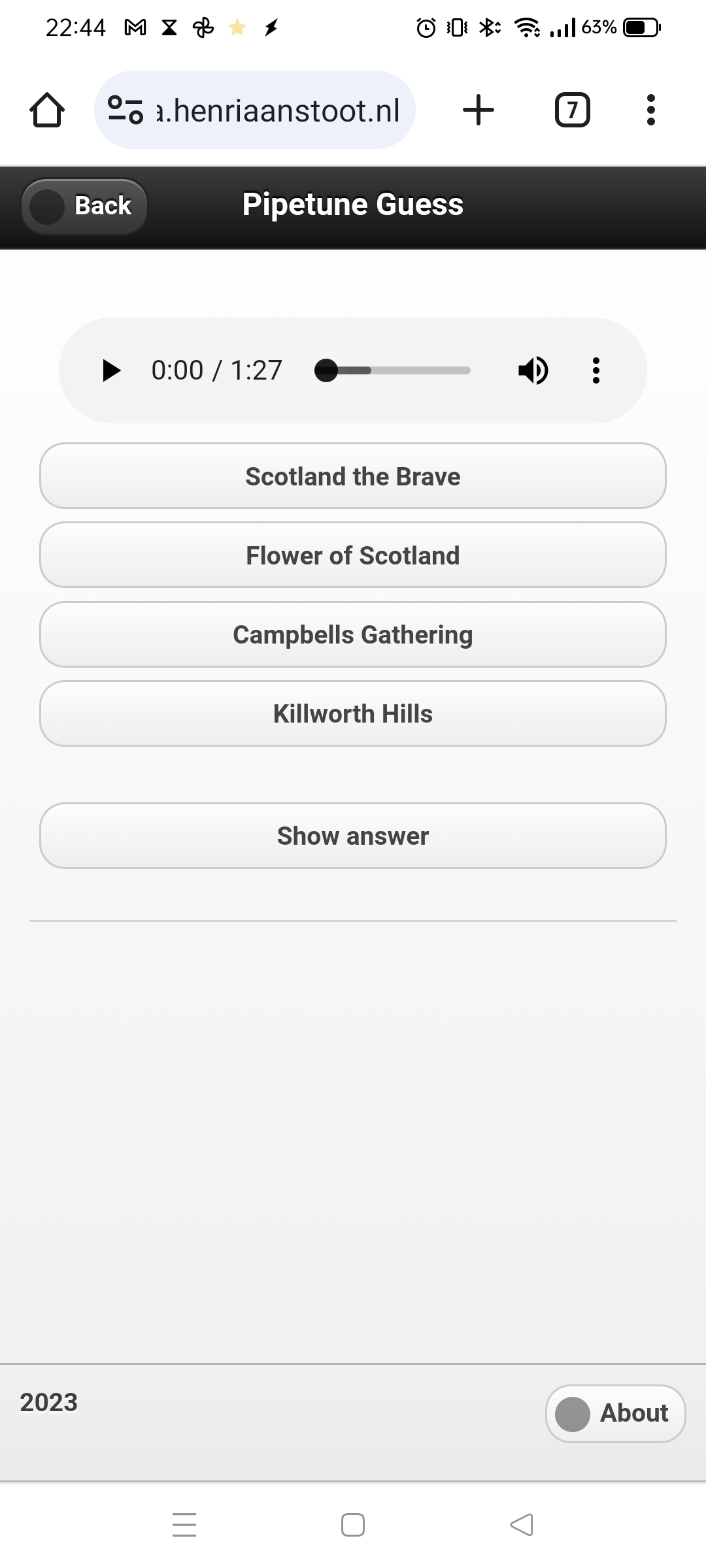
While watching a online python course, I was writing the code for a music guessing game (Highland Bagpipe Tunes) The core is working, now it’s a matter of filling this “pruts” with tunes.
Switching between python, php, bash and C is a nightmare 🙂
A screenshot of work in progress
Then the postman came .. with goodies. I needed the MAX9814 analog microphone with amplifier, all of my other sensors were not up to the task.
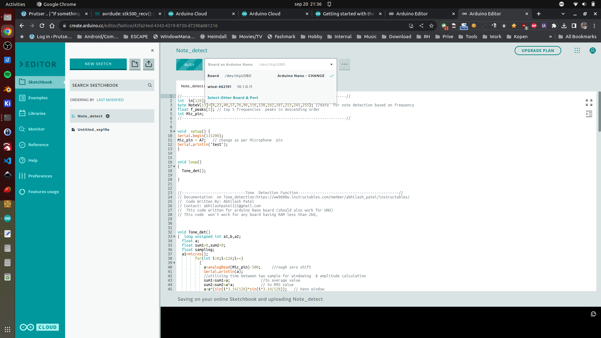
So I switched to this WIP with the MAX9814. I want to make a little gadget using an Arduino and 9 leds, which uses FFT to blink which note I am playing on my Highland Pipes.
So detecting is working, now I have to attach a bunch of leds.
First test using Arduino Cloud (I still prefer PlatformIO) But this is better than the old IDE. (Note, you have to install an agent to connect your browser to a board)
Next thing I did today: Getting my waveshare RP-2040 Zero working with micropython.
Great the little NeoPixel Led on the board.
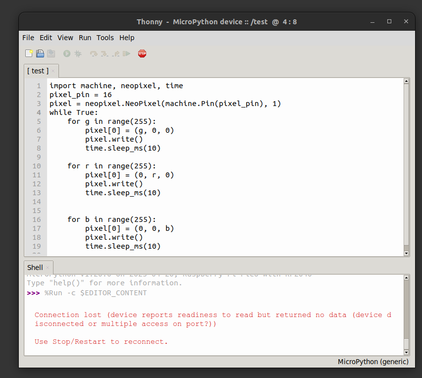
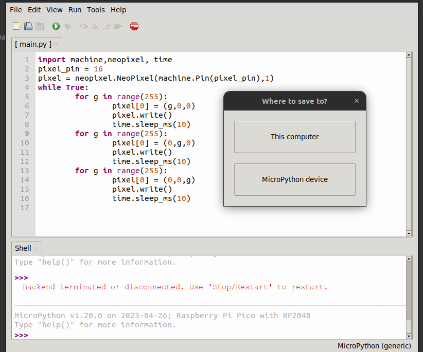
Steps to get this working:
Install Thonny
Connect the rp2040 via USB with the boot button pressed
place RPI_pico.xxxx.uf2 on the mounted usb disk, it will reboot
Run Thonny connect and run a test program
Want to run program @boot ? save -> to device, and call main.py
I’m still having problems getting a working floppy drive in my machine. (Broken FDD card, drive errors etc)
The raster bar (also referred to as rasterbar or copperbar) is an effect used in demos and older video games that displays animated bars of colour, usually horizontal, which additionally might extend into the border, a.k.a. the otherwise unalterable area (assuming no overscan) of the display
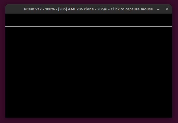
When you look at the left side of the screen you see the color bar in the border (outside the normal pixel screen)
I first tried to get it working in DosBOX, but thats a mess. Good for simple emulation but not hardcore register manipulation.
Below dosbox
Three examples below are in PCem
Not waiting for vsync, gives some idea how much timing is left when doing barsOther effect addedEffect as on the real hardware except emulated using PCeM
use16
org 0x100

CRTC_INDEX = 0x03D4
CRTC_DATA = 0x03D5
INPUT_STATUS = 0x03DA
MAXIMUM_SCAN_LINE = 0x09
LINE_OFFSET = 0x13

jmp start

updown DB 30
direction DB 0
filename DB "shoes.bmp",0

start:
; set mode 320x200 256 colors palette
        mov ah,0x0
        mov al,13h
        int 10h

; clear screen routine, not really needed
clearscreen:
        push ax
        mov ax, 0a000h
        mov es, ax
        pop ax
        xor di, di
        inc ax
        mov cx, 64000 ; 320x200
        rep stosb

; call file loader
        call Loadfile

        push cs
        pop ds

; after displaying the image or displaying an error, wait for keypress to exit
waitforkeyloop:
        call effect     ; Calling the effect
        MOV AH,1
        INT 16h
        JZ waitforkeyloop
        XOR AH,AH
        INT 16h
Exit:
        MOV AX,3        ; default text mode 3
        INT 10h
        MOV AX,4C00h    ; exit to dos (terminate process)
        INT 21h

Loadfile:
        MOV DX,filename
        MOV AX,3D00h    ; open filehandle
        INT 21h
        JC Err1
        MOV BX,AX       ; filehandle
        MOV CX,0FFFFh   ; size
        mov dx,0a000h   ; destination 0000:a000h - Screen memory
        mov ds,dx

        MOV DX,0
        MOV AH,3Fh      ; read from file
        INT 21h
        JC  Err1
        MOV AH,3Eh      ; close filehandle
        INT 21h

        RET
; print error
Err1:
        push cs         ; make ds same as cs
        pop ds
        MOV DX,TxtErr1  ; error
        MOV AH,09h
        INT 21h
        RET

effect:
        cli             ; stop interrupts
        call waitvretrace       ; wait for vertical retrace
        mov al, 0    ; set color index 0 to black (needs to be converted to a function
        mov dx, 3c8h
        out dx, al
        inc dx       ; now 3c9h
        mov al, 0h
        out dx, al   ; set R = 0
        mov al, 0h
        out dx, al   ; set G = 0
        mov al, 0h
        out dx, al   ; set B = 0

; gets start scanline and direction
        mov al,[updown]
        mov ah,[direction]
        cmp ah,0
        jz      addcounter
        dec al
        cmp al,30
        jnz gohere
        mov ah,0
        mov [direction],ah
        jmp gohere
addcounter:
        inc al
        cmp al,100
        jnz gohere
        mov ah,1
        mov [direction],ah
gohere:
        mov [updown],al

; al = scanline, call wait for scanline
        call waithretrace
        mov al, 0    ; set color index 0 to blueish
        mov dx, 3c8h
        out dx, al
        inc dx
        mov al, 11h
        out dx, al
        mov al, 22h
        out dx, al
        mov al, 33h
        out dx, al
; wait 10 scanlines (height of bar)
        mov al,10
        call waithretrace

; draw black again
        mov al, 0    ; set color index 0's rgb value
        mov dx, 3c8h
        out dx, al
        inc dx       ; now 3c9h
        mov al, 0
        out dx, al   ; set R = 11h
        mov al, 0h
        out dx, al   ; set G = 22h
        mov al, 0h
        out dx, al   ; set B = 33h

        sti     ; start interrupts again
        ret

; this waits for vertical retrace
waitvretrace:
        mov dx,INPUT_STATUS
waitv1:
        in al,dx
        test al,8
        jnz waitv1
waitv2:
        in al,dx
        test al,8
        jz waitv2
        ret

; routine that waits for horizontal retrace
waithretrace:
        mov cl,al
        mov dx,INPUT_STATUS
waith1:
        in al,dx
        test al,1
        jnz waith1
waith2:
        in al,dx
        test al,1
        jz waith2
        dec cl
        cmp cl,0
        jnz waith1
        ret

TxtErr1 DB "shoes.bmp not found!",7,10,13,"$"
"If something is worth doing, it's worth overdoing."