I have several ip cameras which monitor movement in and around our home.
I’m using Zoneminder and other home automation systems but i want to scan through a bunch of files uploaded by the security cameras to my secondary fileserver.
So what is interesting?
Major movement compared to a base image
Movement compared to a previous uploaded image
Setting a threshold when to output information (note the 65% mark)
Looking at the output we see: At 76% of the captured images (image 1438) the threshold was above 3000 and the minus gives us the information of the difference between this image and the previous, the X marks the difference between current image and the baseline. | percent | image number | filename | difference | graphbar
Bash script:
#!/bin/bash
threshold=3000
baseline=$( ls  SDAlarm*jpg | head -1)
previous=$( ls  SDAlarm*jpg | head -1)
total=$( ls *.jpg |wc -l)
echo "Number of files : $total"
nr=1
ls *jpg | while read; do
graph="....................................................................................................."
diff=$(compare -verbose -metric MAE $baseline $REPLY /dev/null  2>&1 | grep all | awk '{ print $2 }' | cut -f1 -d. )
prevdiff=$(compare -verbose -metric MAE $previous $REPLY /dev/null  2>&1 | grep all | awk '{ print $2 }' | cut -f1 -d. )
line=$( echo "100 / $total * $nr" | bc -l | cut -f1 -d.)
line=$(( $line + 1))
#echo -n "$line | $nr | $REPLY | "
#echo $diff
draw1=$(( $diff / 100 + 1))
draw2=$(( $prevdiff / 100 + 1))
graph=$(echo $graph | sed "s/./X/$draw1")
graph=$(echo $graph | sed "s/./-/$draw2")
if [ $diff -gt $threshold ] ; then
printf "| %4s %% | %3s | %30s | %5s | %102s \n" $line  $nr $REPLY $diff $graph
fi
nr=$(( $nr +1 ))
previous=$REPLY
done
Want to see only difference with previous image?
change:
if [ $diff -gt $threshold ] ; then into if [ $prevdiff -gt $threshold ] ; then
I’m using below scripts to generate tunebooks. These books I can print OR view on a tablet using my DIY bluetooth page turner. ( see other post )
I often work on tunes, add notes, text or write other versions. So i needed a fast and simple way to re-generate a tunebook. ( hence the date on the title page and in the name, so i know whats the most recent version ) Now i have a separate tunebook for each instrument, with the same looks
What does this script?
Generates a title page using Latex
Generates a tune index, with page numbers ( works with multipage tunes )
Adds bookmarks to the tunes, so you can use the bookmark link in your reader.
000 title 001 index 002 – 099 xyz (extra pages, not in index) 100 – 999 Tunes (sorting)
000 title.pdf
001aIndex.pdf
002 tuneinfo.pdf
100 The Battle of Aughrim.pdf
101 I was born for sports.pdf
105 Cerlew Jig.pdf
110 Chanters Song.pdf
115 Gander at the Pratie Hole.pdf
120 honeymoon.pdf
125 Kitty Goes a-Milking.pdf
130 Terribus.pdf
 ./generatebook
Tune PDFs in directory : 8
Needed index pages : 1
Extra pages : 1
Total pages for tunes : 3
create column page as text
Create Index pdf
Create title page pdf
Add bookmarks : ........
download the package with used files and compilers from here: https://media.henriaanstoot.nl/assembly.tgz
extract with tar xzvf /tmp/assembly.tgz to a directory
start dosbox and mount the directory as C
mount c /path/assembly
Run “a line”, this a batchfile which starts the editor (qedit) When closing the file (esc – q menu) It will compile the assembly and write out a executable
This is the batchfile
@echo off
q %1.asm
cls
masm %1.asm;
link %1.obj;
exe2bin %1.exe %1.com
echo READY!
line assemblycode
    NAME lijnentrekroutine

.286

Code SEGMENT
    ASSUME CS:Code,DS:Code
org 100h
Start:
    mov ax,13h            ;set video mode
    int 10h

    mov bx,100
    mov cx,100
hiero:
    mov dx,0a000h
    mov es,dx
    mov ax,320
    mul cx
    add ax,bx
    mov di,ax
    mov al,2
    stosb
    inc bx
    inc bx
    inc cx
    cmp bx,150
    jnz hiero


    mov ah,8
    int 21h
    mov ax,3
    int 10h

    MOV AX,4C00h
    INT 21h

code ends
end start
While playing with MuseScore…. (Typesetting some scores for Pipes and Flute)
This came in: WOOOT
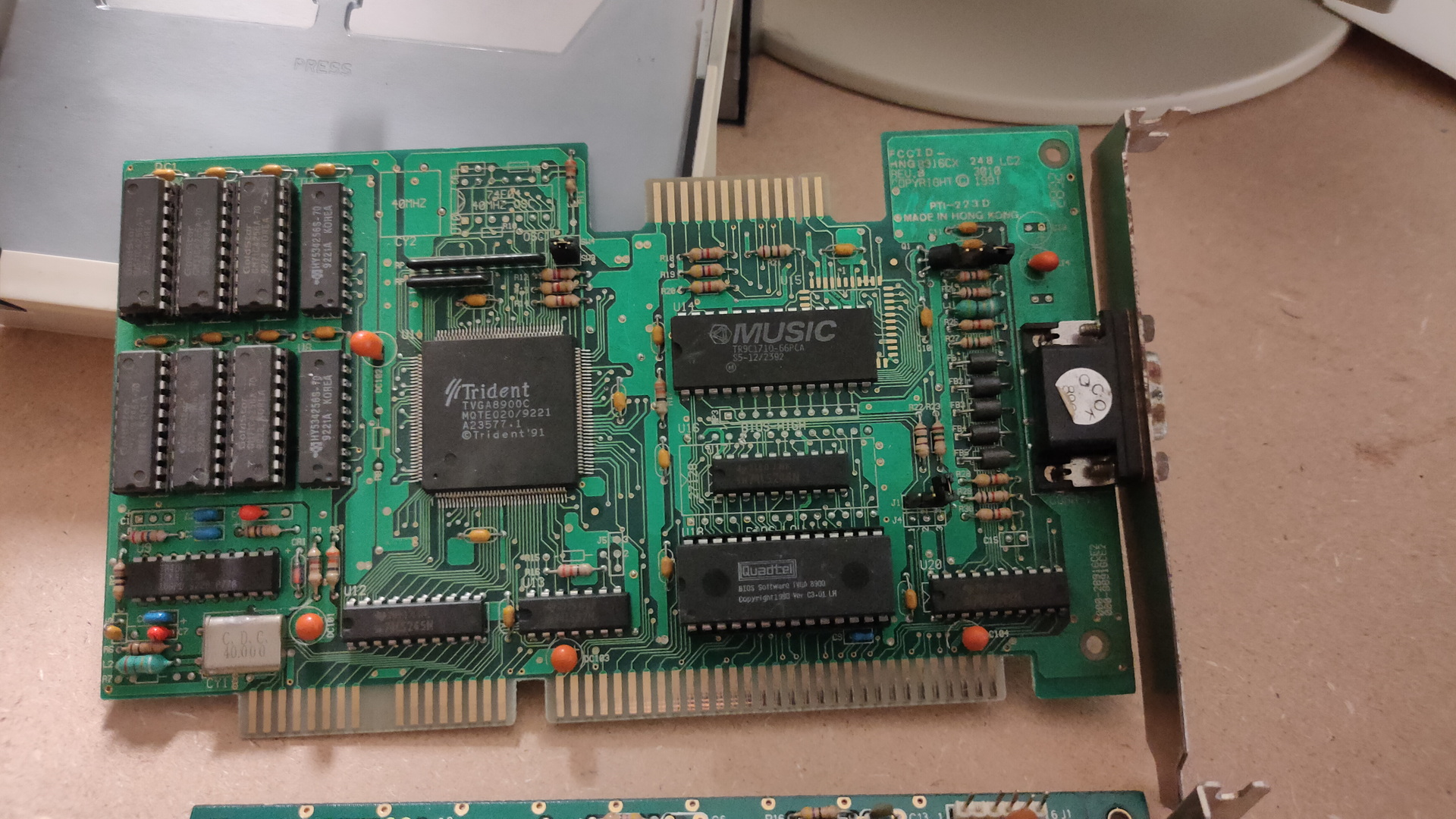
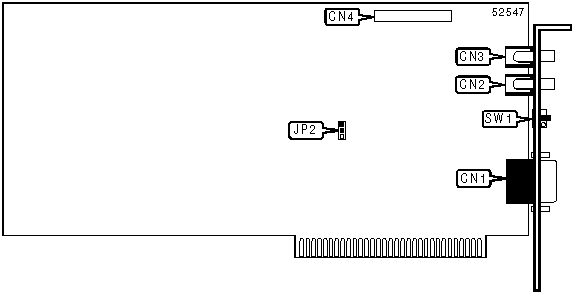
Trident 8900C (1024 x768 max 512Kb)
This is a Trident VGA card. While having a 16bit ISA connector, it can work in a 8bits ISA slot.
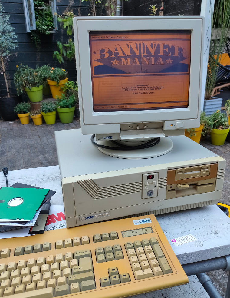
A while ago i bought a Laser XT/3, that’s the one my parents had. This is where i did a lot of assembly programming on. It’s a 8086 cpu, 640K and has a Hercules/CGA graphics card.
I found loads of assembly files and i want to see if i can get it running again. While some code was written for hercules, ( That’s the monochrome image you see in the example above ) and a few for EGA (4 colors).
Most of it was written for VGA. Probably on a later machine like a 80386?
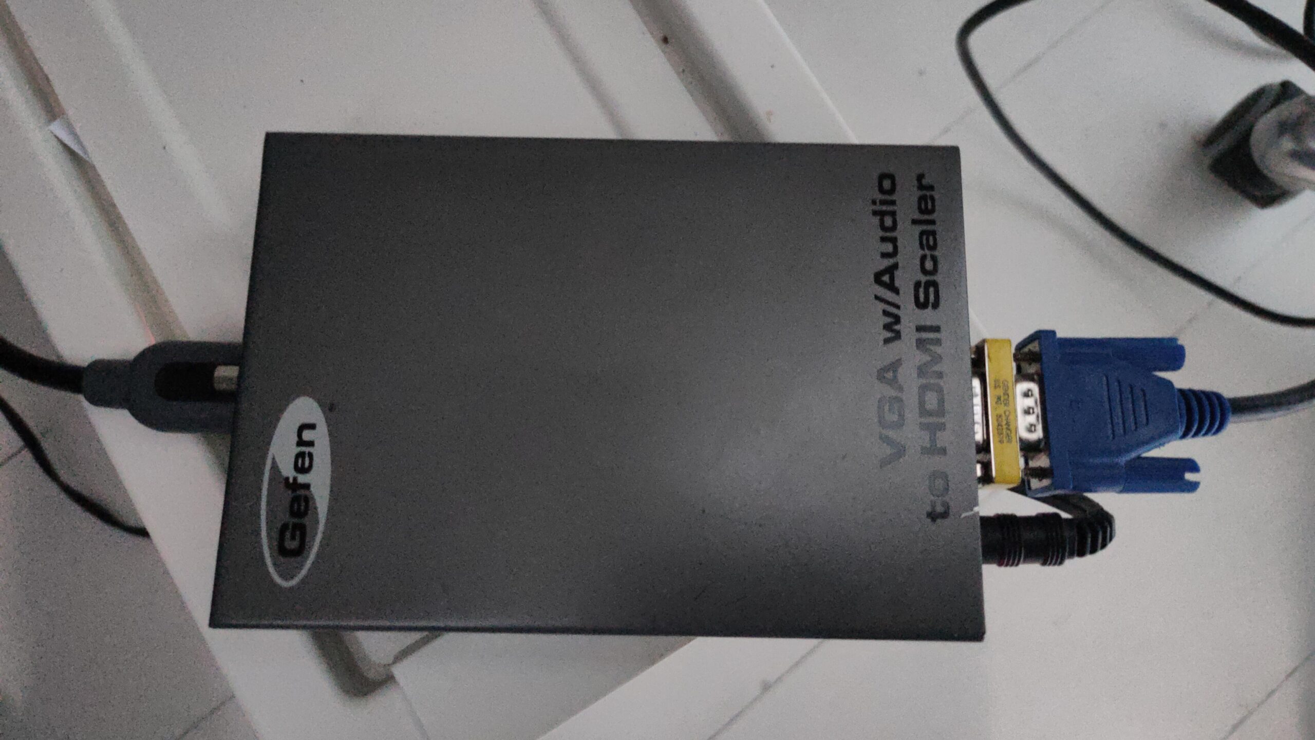
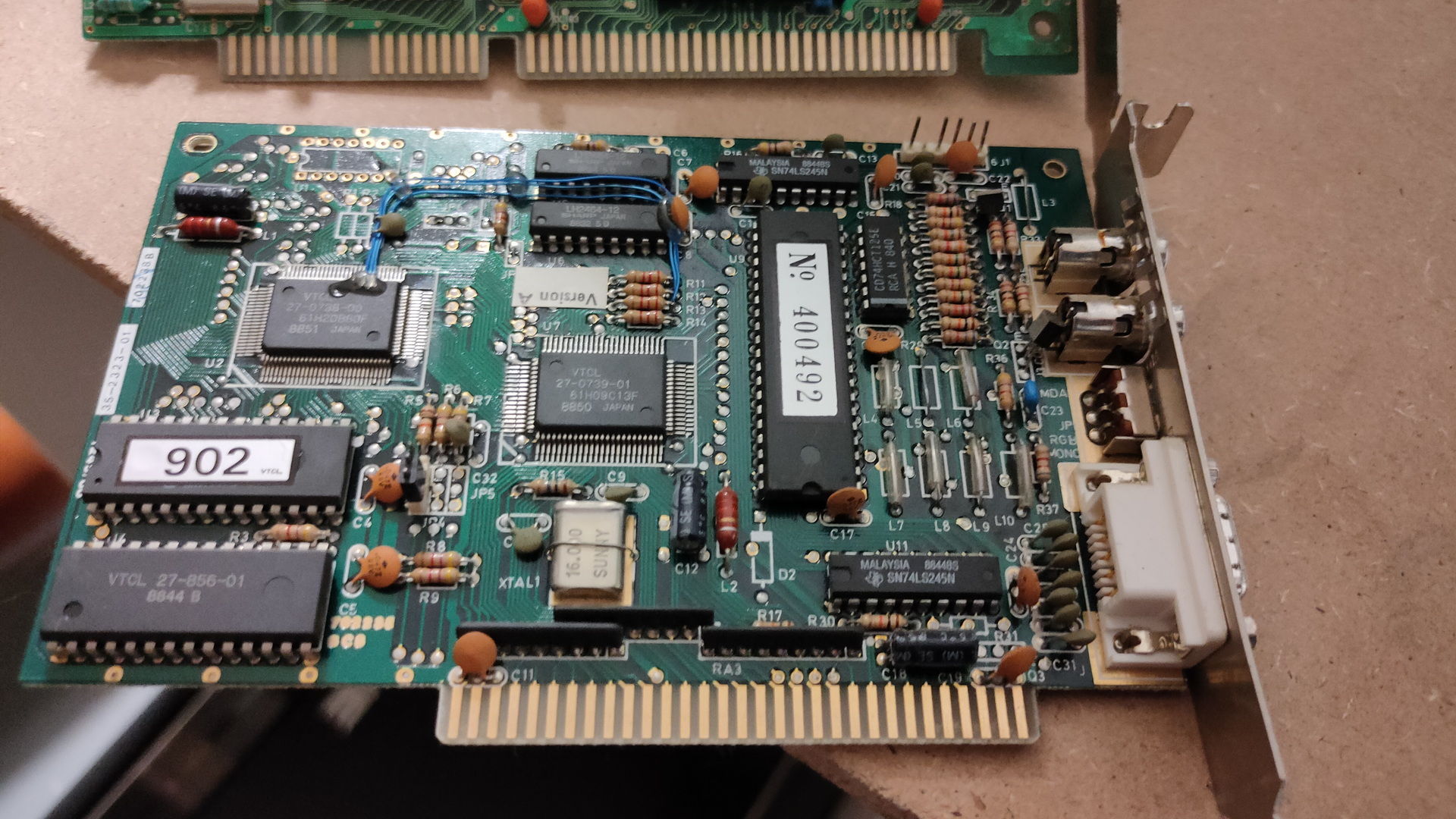
But i know there are vga cards for 8 bit msdos computers, and i found one. ( This one is even autodetect, so no jumpers to figure out)
So i’ve put this card in the machine, turned it on, and it works! I’ve got only 2 examples living on the harddisk of the machine, both black and white … 🙂 I have to search for interesting code in hundreds of files.
Some friends of mine, picture was taken from an amiga genlock digitizerThe intro pages of a “amiga emulator” WHERE is the rest??? (end is a cga starfield demo)
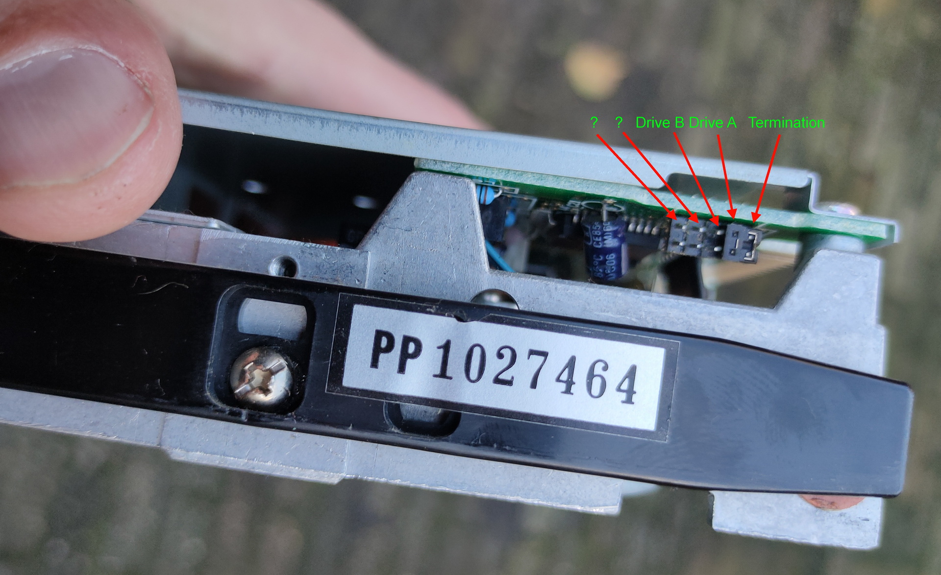
And a boot demo, which was able to start from a bootsector, went into a graphic mode and ran a demo with sound. Edk wrote a sector loader for this. I have some 5.25 inch floppy disks, labelled boot demo. So i wanted to try this today … I needed to change the boot order, so i went online to search for jumper settings.
I see a led when it tries to boot, but my disks are probably formatted 720Kb instead of 360Kb, which this drive is.
So …. TODO!
Find a 720Kb floppy drive (5.25 inch), and sort through my code! There is a 8bit soundblaster compatible soundcard that i bidding on online, hopefully i’ll get it
Assembly and modes
I wasn’t sure how to sort the assembly code into Hercules and VGA compatible, but i used this table (There are also extended modes for higher resolutions)
mode 0x00
text 40×25 gray
mode 0x01
text 40×25 16 colors
mode 0x02
text 80×25
mode 0x03
text 80×25 16 color
mode 0x04
graphics mode (CGA) 320×200
mode 0x05
graphics mode (CGA) 320×200
mode 0x06
graphics mode (CGA) 640×200 (B/W)
mode 0x07
text 80×25 Hercules
mode 0x0F
graphics mode 640×350? gray
mode 0x10
graphics mode 640×350?
mode 0x11
graphics vga 2 colors
mode 0x12
graphics vga 16 colors
mode 0x13
graphics 320×200 256 colors
# Set VGA mode
    mov ax,13h
    int 10h         ;screen 320x200 256 colours

# Exit VGA mode
    mov ax,3
    int 10h         ;screen  80x25 text
    mov ax,4c00h
    int 21h         ;back to DOS
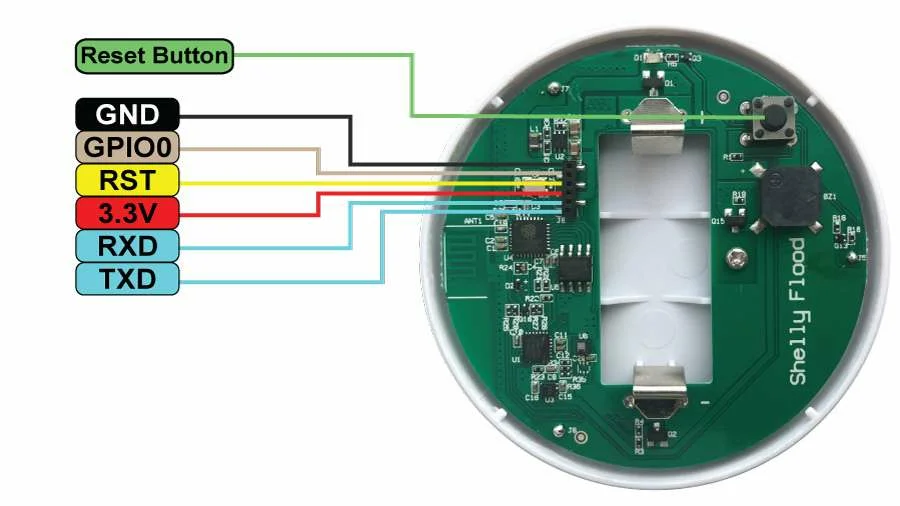
I’ve had this Shelly sensor for a long time. But never posted anything about this. Last weekend we had a -situation- in our kitchen, so what better time to test this device again!
This little disc shaped device has three metal points on its bottom side, those are the flood (water) sensors. It stay’s in sleep mode when all’s good. It does several things when it detects water.
Emits a alarm signal
Wakes-up wifi
Sends a MQTT message (when not connected to the cloud like i have) MQTT is a alarm message AND it wil send the temperature of the device!
After a while (when dry) goes back to sleep
There are connection point on the print you can use .. happy hacking!
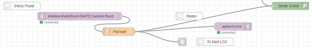
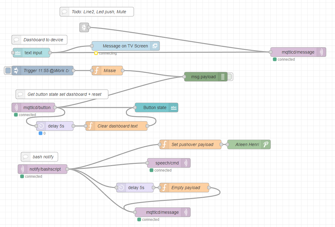
My node-red configuration
Above is the part where the mqtt messages gets processed by Node-Red Sending it to PushOver and my little MqttLcdNotifier
Above is the MqttLcdNotifer .. there are several parts to this
Top line is from shelly flood and other notifications
Text input puts text from the NR GUI on my TV and the LCDDisplay
same parts are being used by my 3D printer when the print tool is getting TO hot, or printing is finished
Trigger at work WAS a notification for work .. nonfunc
mqttlcd-button is the mqtt message send from the display (the one that i was pushing) to stop the beeping and clears the display
Bash notify, is as previously posted a flow which i can control from my linux machines notify “compiling complete” for example. This is also being broadcast from my livingroom using speakers. (See separate post about this)
Wellll, put this in place 2 years ago, never looked at it again .. still works
Februari 2021 i made a website to view images and movies in a browser to do some quick sorting. (borrowed some code from a codepen page i recall correctly) At the time i didn´t have a good way to view webp webm media. I wanted to view multiple files at the same time, and make it short and simple.
BTW no webserver needed, just open the file from a directory! jpg’s png’s webm webp mp4 svg and animated gifs work. (maybe more, didn’t test more, whatever your browser supports)
With recent updates of the chrome browser the video attributes to mute is broken, i so made a workaround. Also everything is in one file now. Except for one issue .. i couldn´t create one file for images AND videos.
There is a piece of javascript i could not fix … yet I have to do execute a document.createElement which is different for images and videos. Also the attributes of video are mute,autoplay,loop,playinline
Last year i made a script for a friend who wanted to detect visually if his garden sprinkler was on or off. A few days ago i saw someone who wanted to see if things where moving in his house. (didn’t trust his landlord i think) But he only had a dumb/simple/cheap camera .. so it had no motion detection.
I was thinking of my script, and could easily adapt it for this usage.
Most ipcams have somekind of URL/API you can use to capture a image. Some examples below
So using below script i can capture a image, compare it to the previous, and when it’s above a certain threshold sends a email.
#!/bin/bash
# Only uses wget and image-magick
treshhold=500
fuzzyness=20%
# CHANGE WEBCAM THINGY TO OWN URL AND CREDENTIALS
wget -q "http://webcamip/cgi-bin/api.cgi?cmd=Snap&channel=0&user=user&password=password" -O previous.jpg
while true;  do
wget -q "http://webcamip/cgi-bin/api.cgi?cmd=Snap&channel=0&user=user&password=password" -O current.jpg
value=$(compare -fuzz $fuzzyness previous.jpg current.jpg -metric mae diff.jpg 2>&1 | cut -f1 -d.)
if [ $value -gt $treshhold ] ; then
echo "ping $treshhold"
echo "Something moved" | mail -s "Movement" user@example.com -A diff.jpg
fi
# Comment below if you want to compare against a base line .. not previous image
cat current.jpg > previous.jpg
sleep 60
done
Example previous picture
Example current picture
I got mailed with result
Hints tips:
Use crop to detect only a part.

copy current.jpg to a second file
Use painting black a part and compair with different treshhold fuzzyness to get different hotspots.

Below detects RED, use above ide with crop to detect red/green/blue leds

compare -verbose -metric mae 1.jpg 2.jpg /tmp/1.diff
1.jpg JPEG 2560x1920 2560x1920+0+0 8-bit sRGB 248819B 0.050u 0:00.057
2.jpg JPEG 2560x1920 2560x1920+0+0 8-bit sRGB 248949B 0.030u 0:00.137
Image: 1.jpg
  Channel distortion: MAE
  Channel distortion: MAE
    red: 12517.5 (0.191005)
    green: 11967.1 (0.182607)
    blue: 12492.8 (0.190628)
    all: 12325.8 (0.18808)
1.jpg=>/tmp/1.diff JPEG 2560x1920 2560x1920+0+0 8-bit sRGB 1.19495MiB 1.470u 0:00.197
The goal of this project is to have a raspberry-pi with a screen wich shows network information. It wil be using a battery, touchscreen .. maybe some status leds. When debugging network issues we want to have information when/if/how a network port works on our switches.
It should show:
dhcp ip
gateway
can access internet?
speedtest
detect if vlan tagged network packets are present on the port?
icmp test
list of detected nearby hosts?
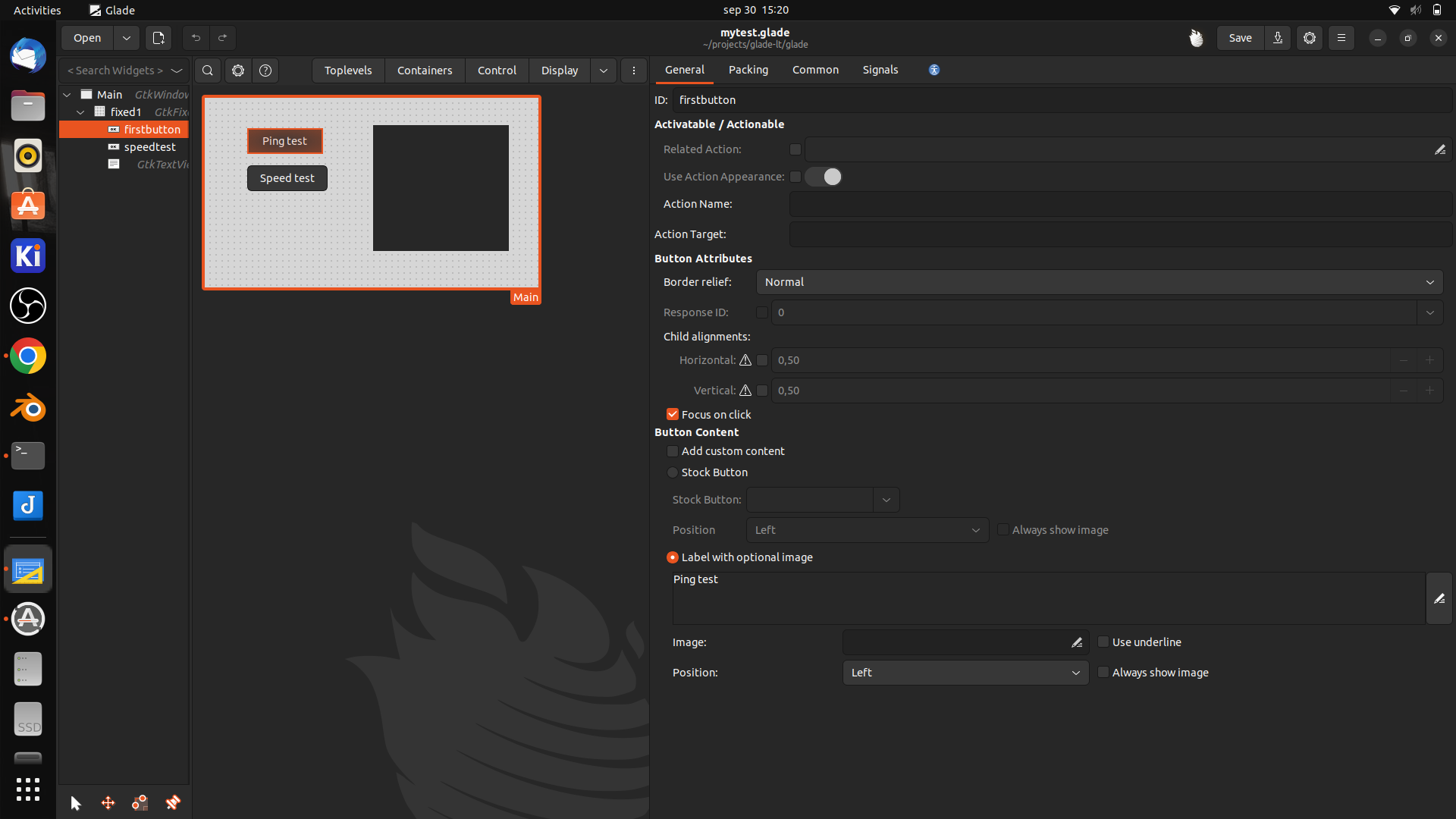
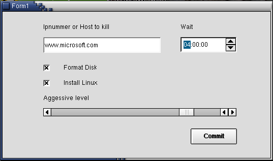
A long time ago i played with glade and C / Perl.
But i’d rather use python so i’m looking into glade/python combi for this little project.
Glade is a gnome/GTK user interface RAD tool. (Rapid Application Development)
i’ve used zenity and yad before to create simple gui’s for bash scripts, these where only for quick and dirty solutions. (See other posts) Glade is a far better solution, but a little harder to use.
Below is a little framework i started with
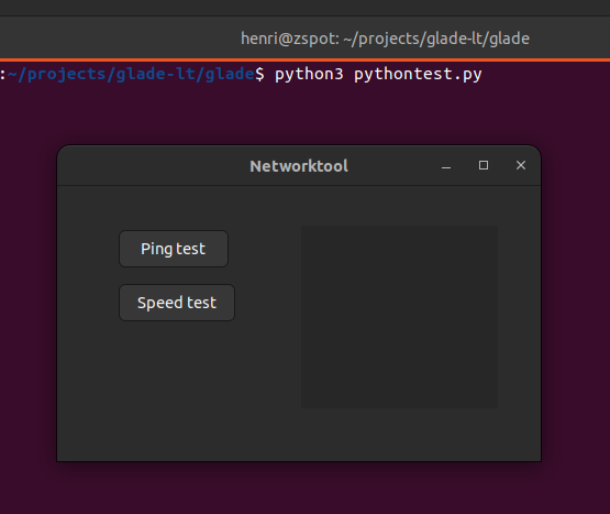
Python script
import gi

gi.require_version("Gtk", "3.0")
from gi.repository import Gtk

class Handler:
    def onDestroy(self, *args):
        Gtk.main_quit()

    def on_firstbutton_clicked(self, button):
        print("Ping test")

builder = Gtk.Builder()
builder.add_from_file("mytest.glade")
builder.connect_signals(Handler())

window = builder.get_object("Main")
window.show_all()

Gtk.main()
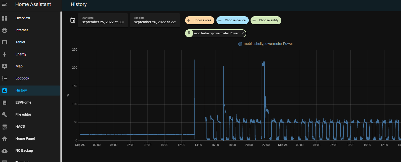
Having a lot of devices and running a Lab wil use a lot of energy. Now with the energy crisis in Europe, i had to take a closer look at whats using power in my house.
I notished some weird usage patterns while measuring.
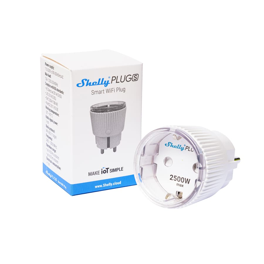
I’m using a few shelly power plugs, to measure devices and powerstrips.
With these devices you can control devices connected to it. On/Off/Timer etcetera. It wil measure the power usage in watts, and it even got a temperature sensor. I like the fact that it perfectly integrates into your home automation using an extensive API. curl commands to controll, and even MQTT messaging. Intergrating in Home Assistant is a breeze.
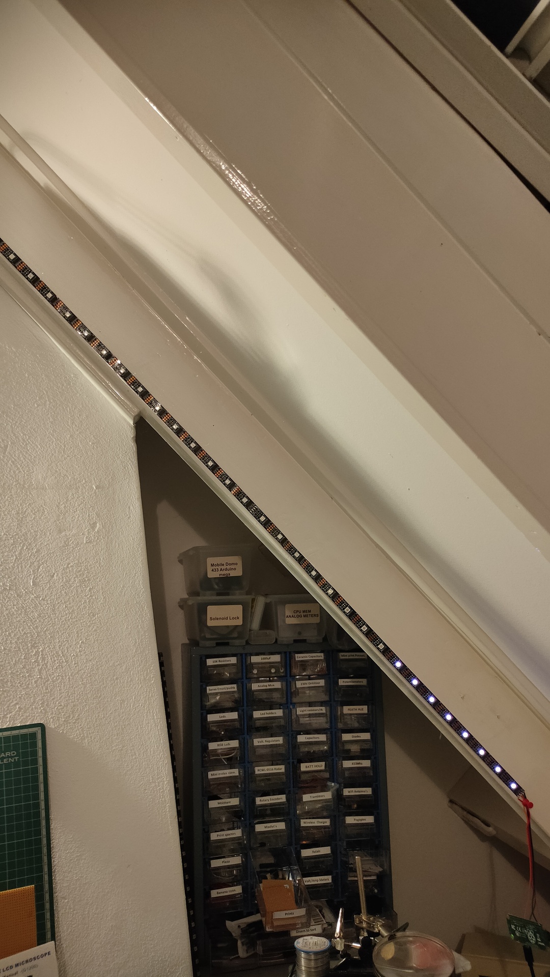
So i was monitoring a bunch of stuff using Nodered/Grafana/Homeassistant and saw some recurring usage. But being always late to check things, i made use of my ledserver i’ve build a long time ago.
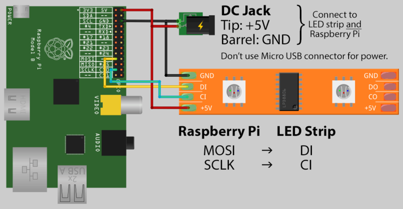
This ledserver consists of a Raspberry Pi Zero, with a led string and a API written in python.
Below is autostarted on the Raspberry
( I made this ledserver for work, it showed the status of servers and services. Beside that every colleage had a range which he could use for his own scripts. I made some little bash script templates to have led funtions standard in your bash profile.
#!/usr/bin/python


# apt-get install python-flask
#

import Adafruit_WS2801
import Adafruit_GPIO.SPI as SPI
import struct

from flask import Flask, render_template, request
app = Flask(__name__)

PIXEL_COUNT = 32
SPI_PORT   = 0
SPI_DEVICE = 0

pixels = Adafruit_WS2801.WS2801Pixels(PIXEL_COUNT, spi=SPI.SpiDev(SPI_PORT, SPI_DEVICE))

pixels.clear()
pixels.show()

@app.route("/led/<deviceName>/<color>")
def action(deviceName, color):
        if deviceName == 'reset':
                print ("reset")
                pixels.clear()
        print (deviceName)
        led = int(deviceName)
        s = color
        r = int(s[ :2], 16)
        b = int(s[2:4], 16)
        g = int(s[4: ], 16)

        pixels.set_pixel_rgb(led, r,g,b)
        pixels.show()

        templateData = {
                'rled'  : r,
                'bled'  : b,
                'gled'  : g,
                'deviceName'  : deviceName,
        }
        return render_template('index.html', **templateData)

@app.route("/control/<controlcommand>")
def actioncommand(controlcommand):
        if controlcommand == 'clear':

                print("clear")
                pixels.clear()
                pixels.show()

        templateData = {
                'controlcommand'  : controlcommand,
        }
        return render_template('index.html', **templateData)

@app.route("/range/<start>/<stop>/<color>")
def rangecommand(start,stop,color):
        s = color
        r = int(s[ :2], 16)
        b = int(s[2:4], 16)
        g = int(s[4: ], 16)
        startled = int(start)
        stopled = int(stop)
        while (startled < stopled):
          pixels.set_pixel_rgb(startled, r,g,b)
          startled=startled + 1
        pixels.show()

        templateData = {
                'rangecommand'  : rangecommand,
        }


        return render_template('index.html', **templateData)


if __name__ == "__main__":
   app.run(host='0.0.0.0', port=8080, debug=True)
Now you can control the leds with a simple curl command:
So today i made a little script to show power usage.
I’m reading the current power usage from a LS120 Youless
Youless LS120 device, which you can connect to your P1 connector.
With below bash script i’m reading the webinterface and update the ledstring. I was using this ledserver for general notification usage. Below a 2 minute hack ..