I’ve been busy programming Python and NodeRed for a client. But these are the things I’ve done in the last days.
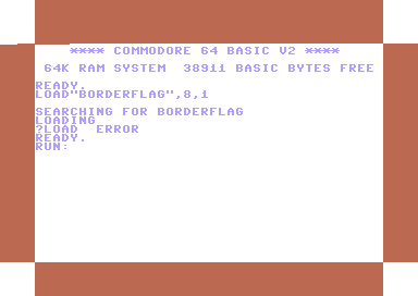
C64 Assembly: Breaking borders, using sprites and multicolor font intro.
It does not look impressive, but I’ve learned a lot. Found a new way (for me) to open borders and change border colours on predefined raster lines. Sources will be posted.
KiCad tutorial, posted on YT also because I could not find many resources about the subject online. Maybe it’s helpful
Video editing using Kdenlive.
Edit: Even faster, use Netlabels, no need to join pins. Press L (uppercase) select pin 1, name 1. Press and hold insert until all pins named. Copy paste socket 5 times and goto your PCB tab.
This movie is about creating a backplane for a 6502 SBC I’m building. It is real-time and below 4 minutes.
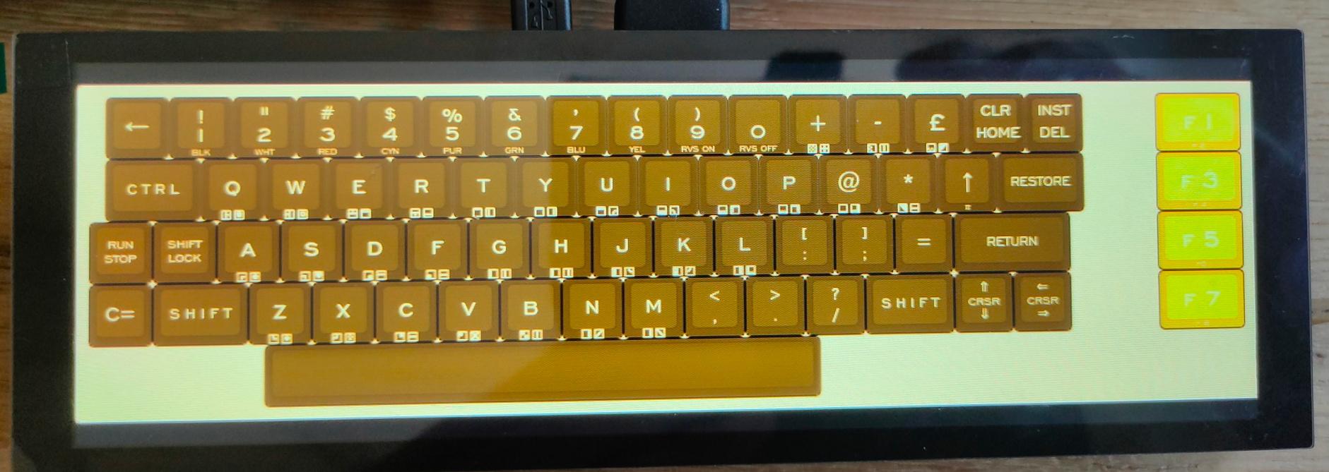
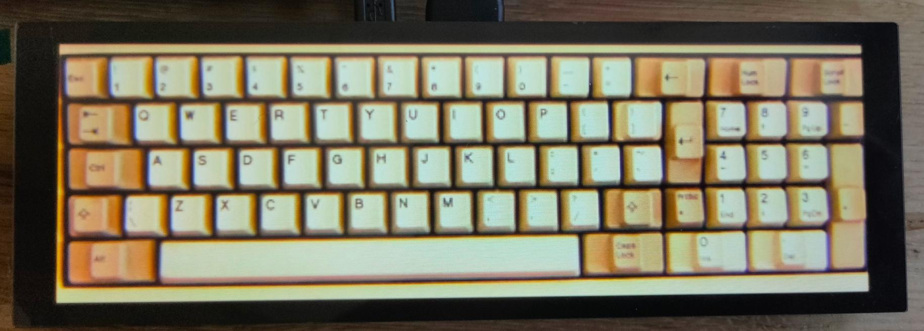
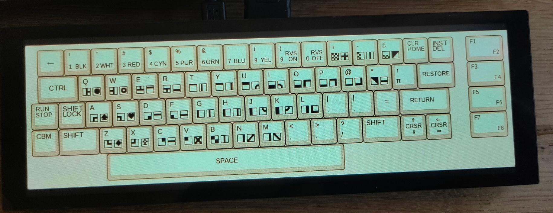
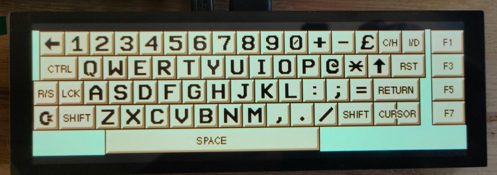
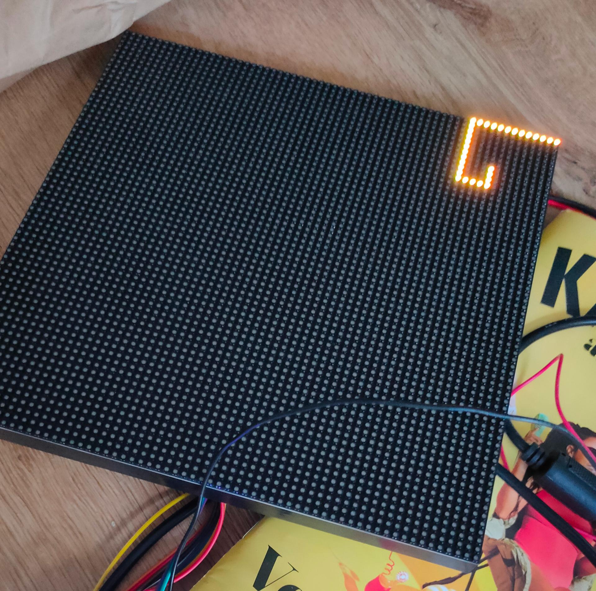
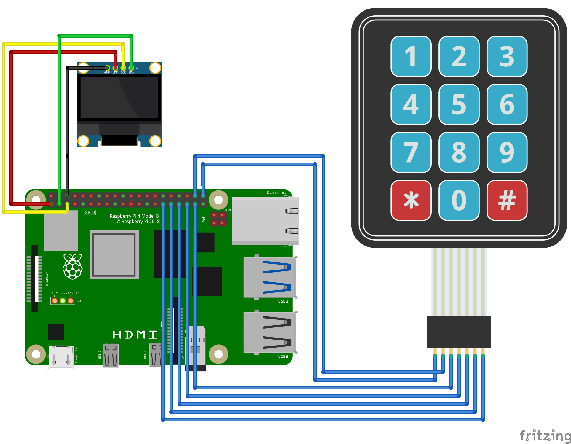
Multi Keyboard
My small multitouch screen came in. This is for my previously mentioned multi-computer case.
It is going to show multiple keyboard layouts for different systems. (See previous posts about this)
Waveshare display, Raspberry Zero as HID device, using USB and pin emulated keyboards. (c64 matrix, AT (DIN) keyboard, ps2 keyboard)
Some example screens
Vic-20
Photo-realistic
Petscii C64
Another C64
I’m also going to make a layout like the keyboards on my 8085
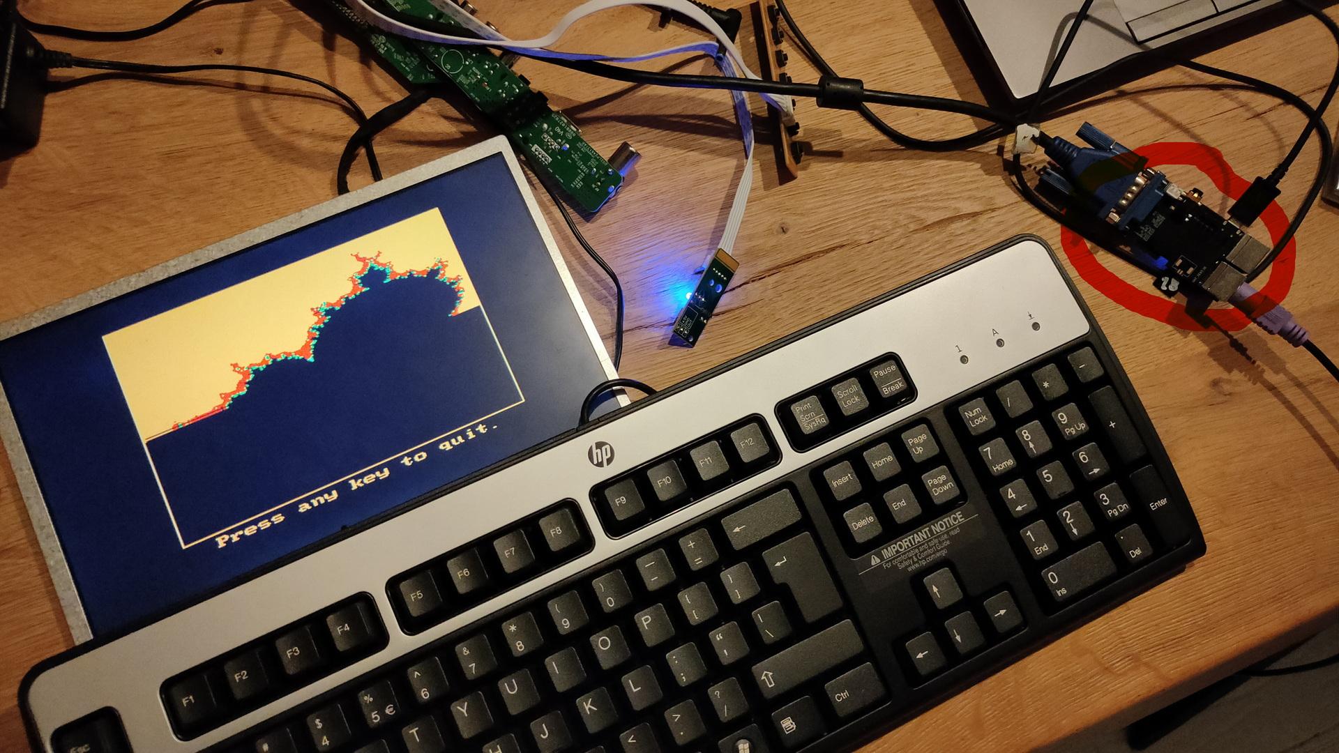
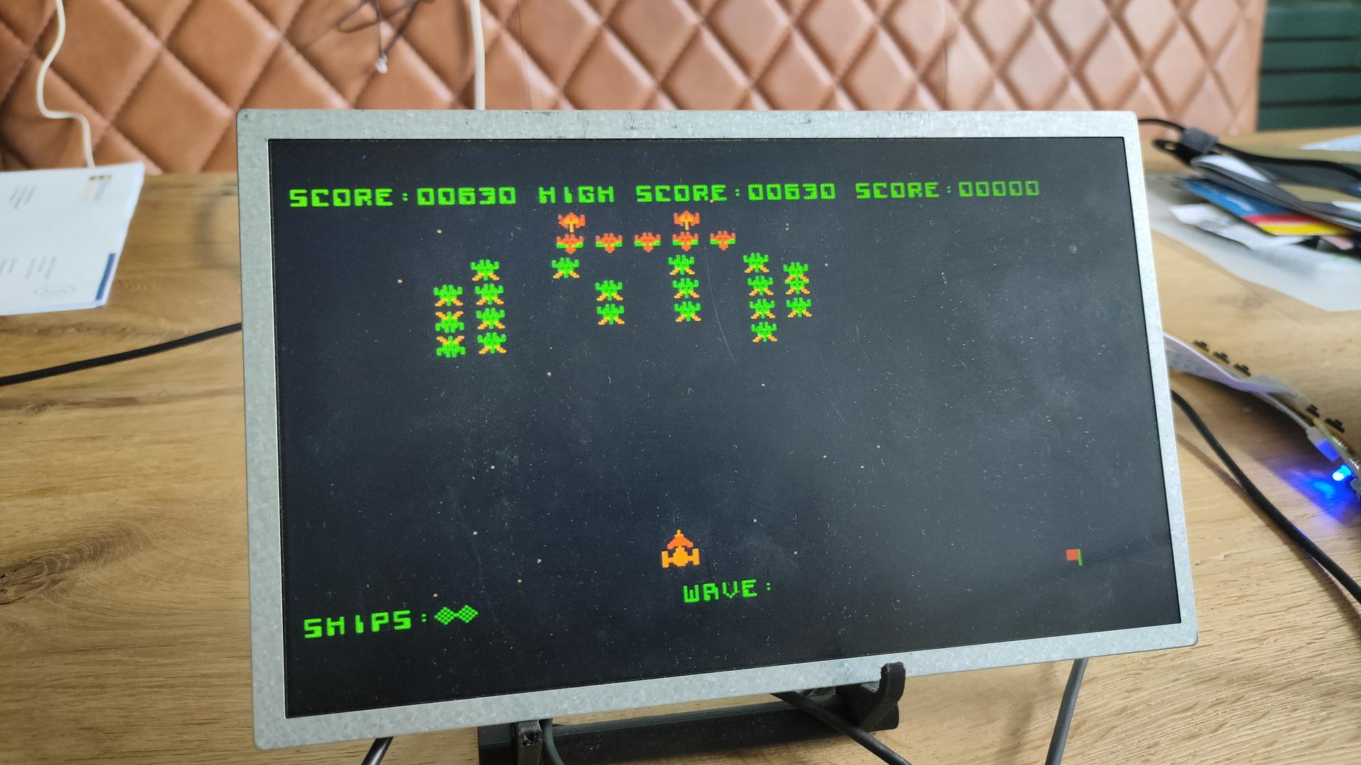
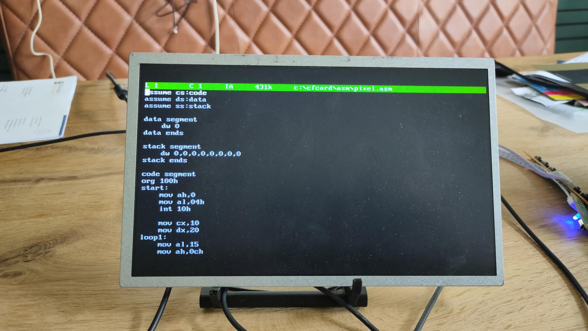
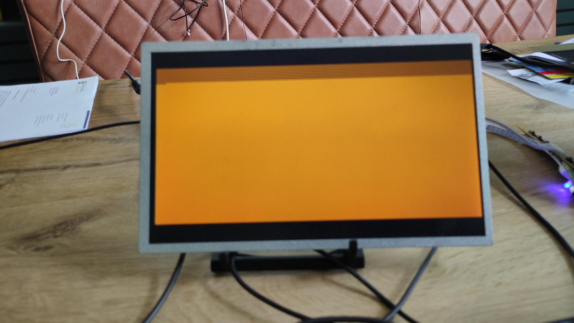
GameA masm setupExample asm program to see gfx capabilities
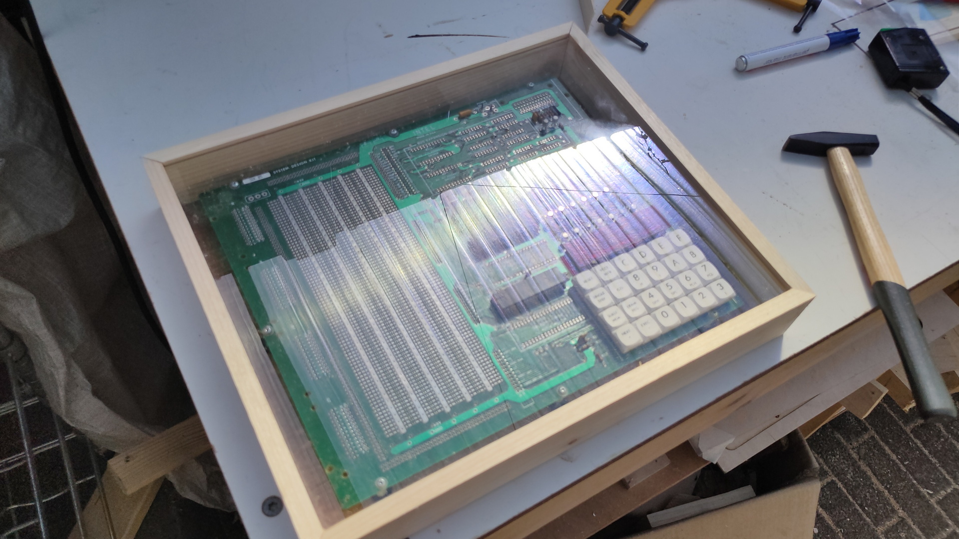
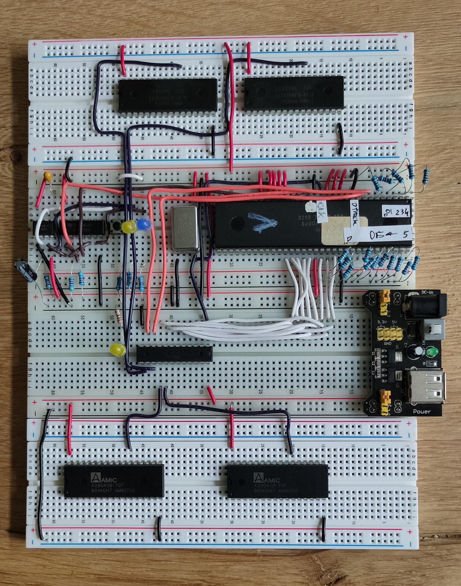
68000 Progress
My address decoder seems to work (using an ATF22v10C) See previous posts.
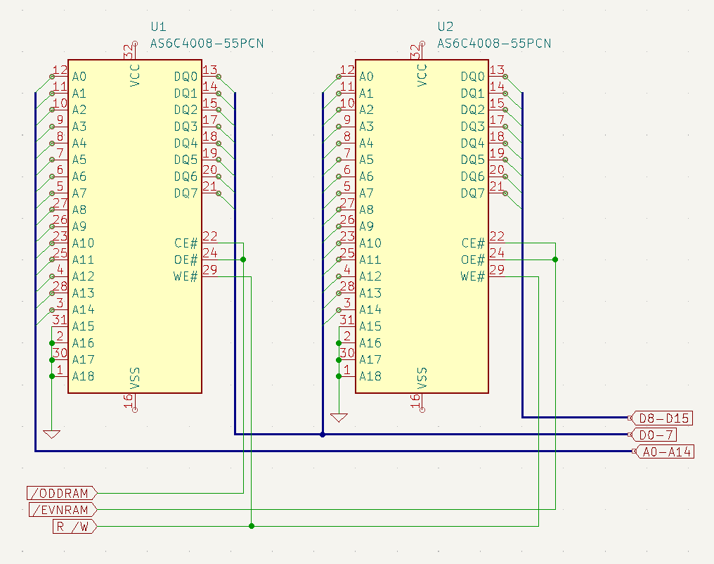
Also new Rom and Ram chips. These are 8 bits, but the 68000’s data bus we need two (Odd and Even Addresses)
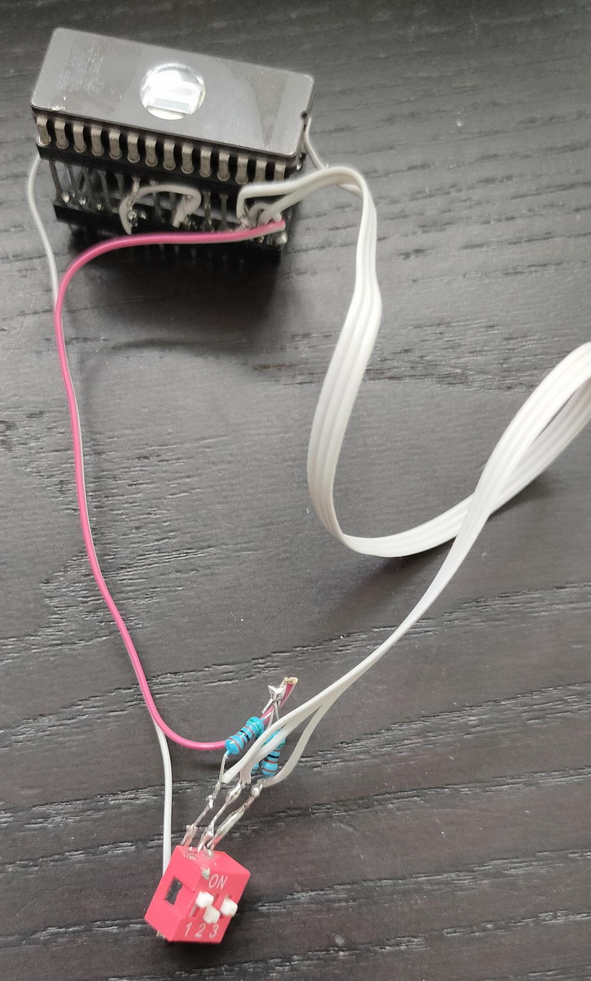
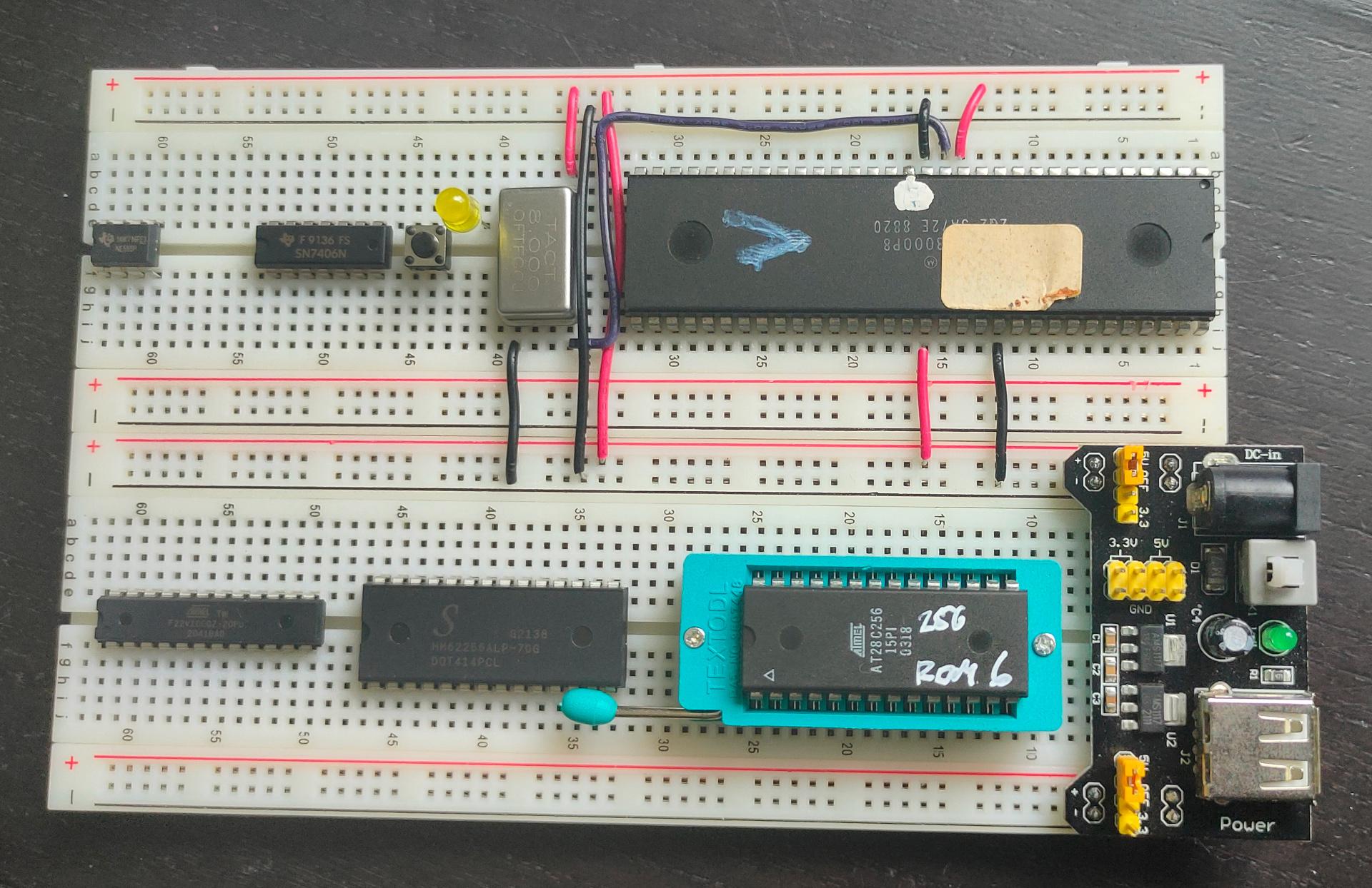
C64 Hacks
I made a proof of concept for a Rom switcher. 8 Different Roms can be selected using the dip switches. (Dipswitches are being replaces bij something smarter in the future, like an Arduino Nano (like Adrian Black’s solution)
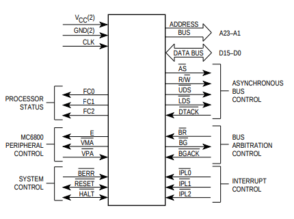
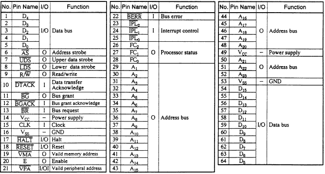
PROCESSOR FUNCTION CODES (FC0, FC1, FC2) These function code outputs indicate the mode (user or supervisor) and the address space type currently being accessed.
The following table shows the
meaning of these three bits.
FC2 FC1 FC0 Meaning
0 0 0 Not used
0 0 1 User data
0 1 0 User program
0 1 1 Not used
1 0 0 Not used
1 0 1 Supervisor data
1 1 0 Supervisor program
1 1 1 Interrupt Acknowledge
These outputs can therefore inform external circuitry what is happening
inside the 68000. They could, for example, be used to switch in differentbanks of memory.
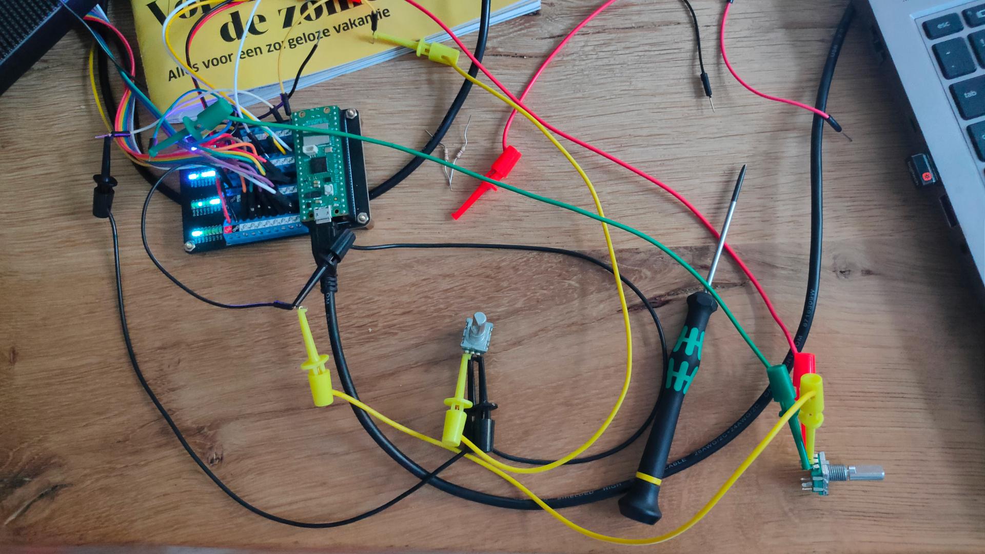
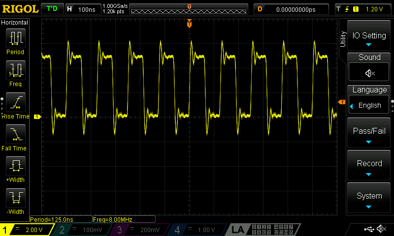
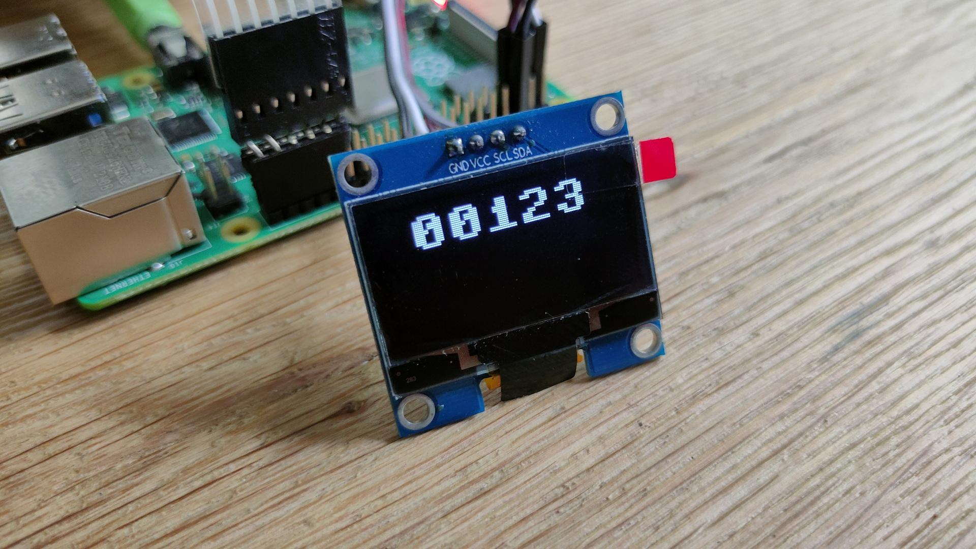
Using a small 8266 with a display, I wanted to see if it’s useful to monitor this information.
So using a trick with the uln2804/uln2803 as level convertor (don’t connect the VCC, and the output will drop to a level that is around the 3.3v. (I was out of bi-directional level convertors)
Latch demo
I’ve been using latches in the past, but I wanted to show how it works using a little demo setup. Below movie is for the Bus Controller I posted recently.
While busy fixing my business site, and working for a customer, I build a testing rig for the 68000.
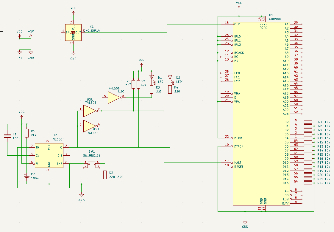
I first made a power-on reset schematic. The timing is different from the 6502 power-on reset, and the 68k needs HALT and RESET being pulled low.
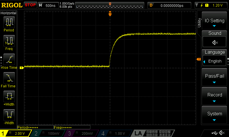
Inverted reset signal (before the 74ls06 invertor)
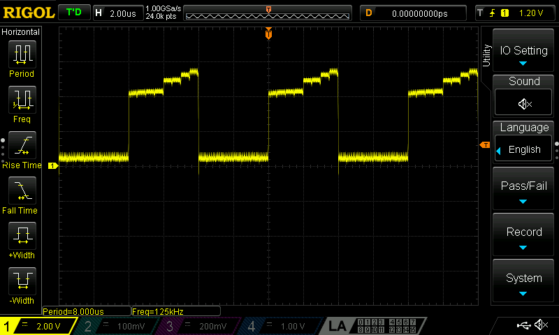
Pulse from A17
Schematic with poweron reset, some leds and 8mhz crystal Lines pulled to GND or VCC are at least needed to get a running CPU. Data bus resistors are needed because data is r/w
All Data lines are pulled low, emulating opcode 00 00 https://68k.hax.com/ORI%20to%20CCR This will do nothing weird, and will increment the address and try to read the next opcode. Resulting in an endless incrementing address bus, I’ve put a Led (Red)on Address A17.
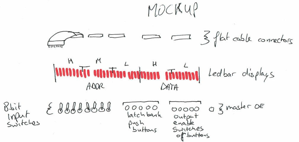
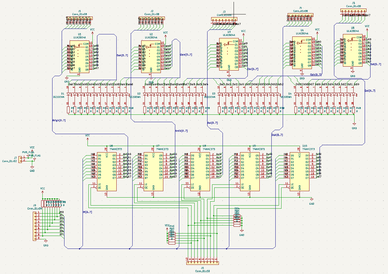
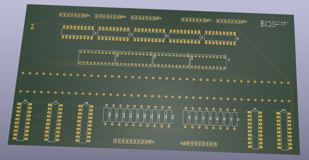
For my 68000 POC I’ll need a way to test Address and Data buses. Something I also wanted for my 6502.
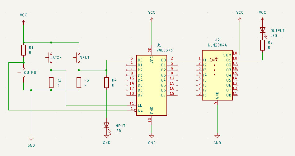
So I drew a schematic to make a generic bus manipulator. (Address, Data and some control lines)
Devices I want to control:
6502 – 16 addresses and 8 bit data
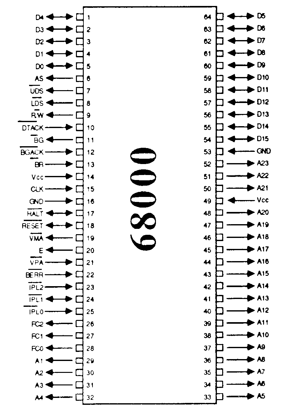
6800 – 24 address lines and 16 bits data
808x
LCD Displays – 8 bit data – enable, read/write and register select
SID Music Chip, AY-3-8910 Music chip
I will be using 8 input switches I can latch into 74HC373 chips. (3x 8 bit for addresses, or 2x 8 bit and extra control lines + 2x 8 bit datalines) Using ULN2804A or ULN2803A darlingtons I can use ledbars to display the bus data AND the latched data. Using 5 pushbuttons I can choose which one (or multiple banks will be latched. Other 5 buttons shall control the OUTPUT enable (OE), which also can be toggled using 1 master switch. (Not yet in the schematic)
Made a clock circuit and busy designing a power-on-reset schematic. I’ve made one before, but this circuit needs RESET and HALT being pulled low.
8mhz 5V
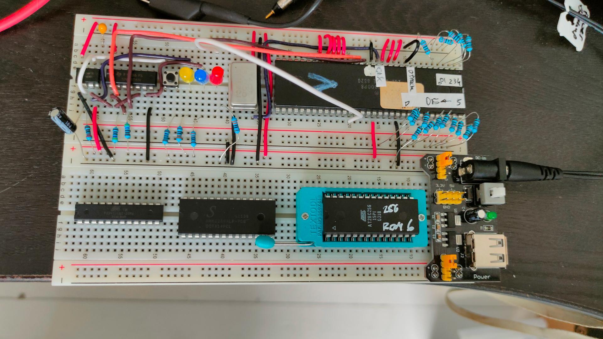
The 68000 being 24 bit address and 16 bit data needs 2x 8-bit roms and 2x 8 bit ram, but i didn’t have the components yet in this picture.
Address decoder using ATF22V10C is also halfway. Schematics online soon.
Started a protected Git repo for C64 demo and proof of concepts for our old ICECREW group.
Installed Gitea, behind a reverse proxy. Part of reverse proxy
ProxyRequests Off
ProxyPreserveHost On
SSLProxyVerify none
SSLProxyCheckPeerCN off
SSLProxyCheckPeerName off

<Location />
ProxyPass   http://10.x.y.z:3000/
ProxyPassReverse  http://10.x.y.z:3000/
Require ip 213.10.144.27
Require ip a.b.c.d
Require ip e.f.g.h
</Location>
Gitea config with token login over https
Generate token
Login https://icecrew.henriaanstoot.nl/

Select your profile (upper right)

And select Settings > Applications

Select a name for your token. And press generate

Top screen shows a token, copy this!

Create new project
Press explore (upper left)

Select organisation and icecrew

Press New Repository, give a name and create

(press https when not defaulted, there is NO ssh to this server)

The example is wrong! (Use below changing TOKENHERE and PROJECTNAME

touch README.md
git init -b master
git add README.md
git commit -m "first commit"
git remote add origin https://TOKENHERE@icecrew.henriaanstoot.nl/icecrew/PROJECTNAME.git
git push -u origin master

Clone a project
Goto a project

press HTTPS when not defaulted to this.

git clone https://icecrew.henriaanstoot.nl/icecrew/borderflag.git

edit .git/config and add your token to the url ! to push
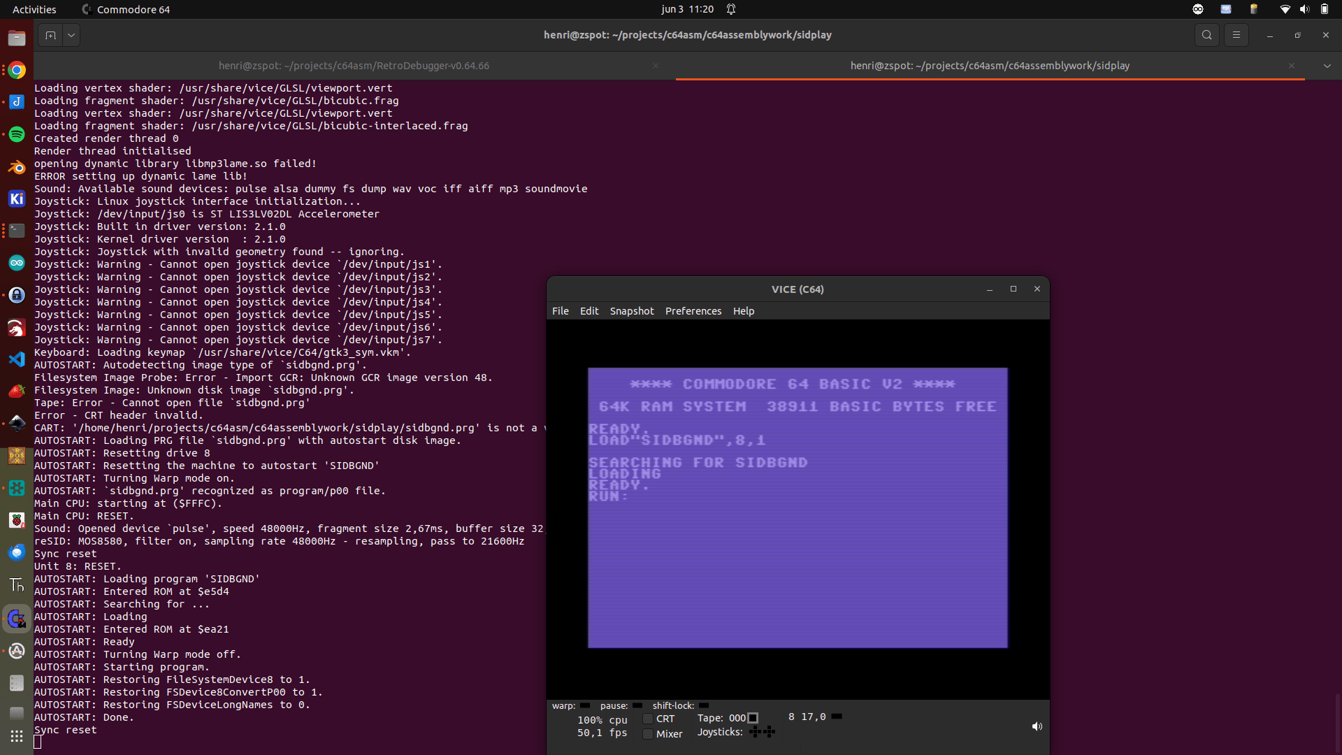
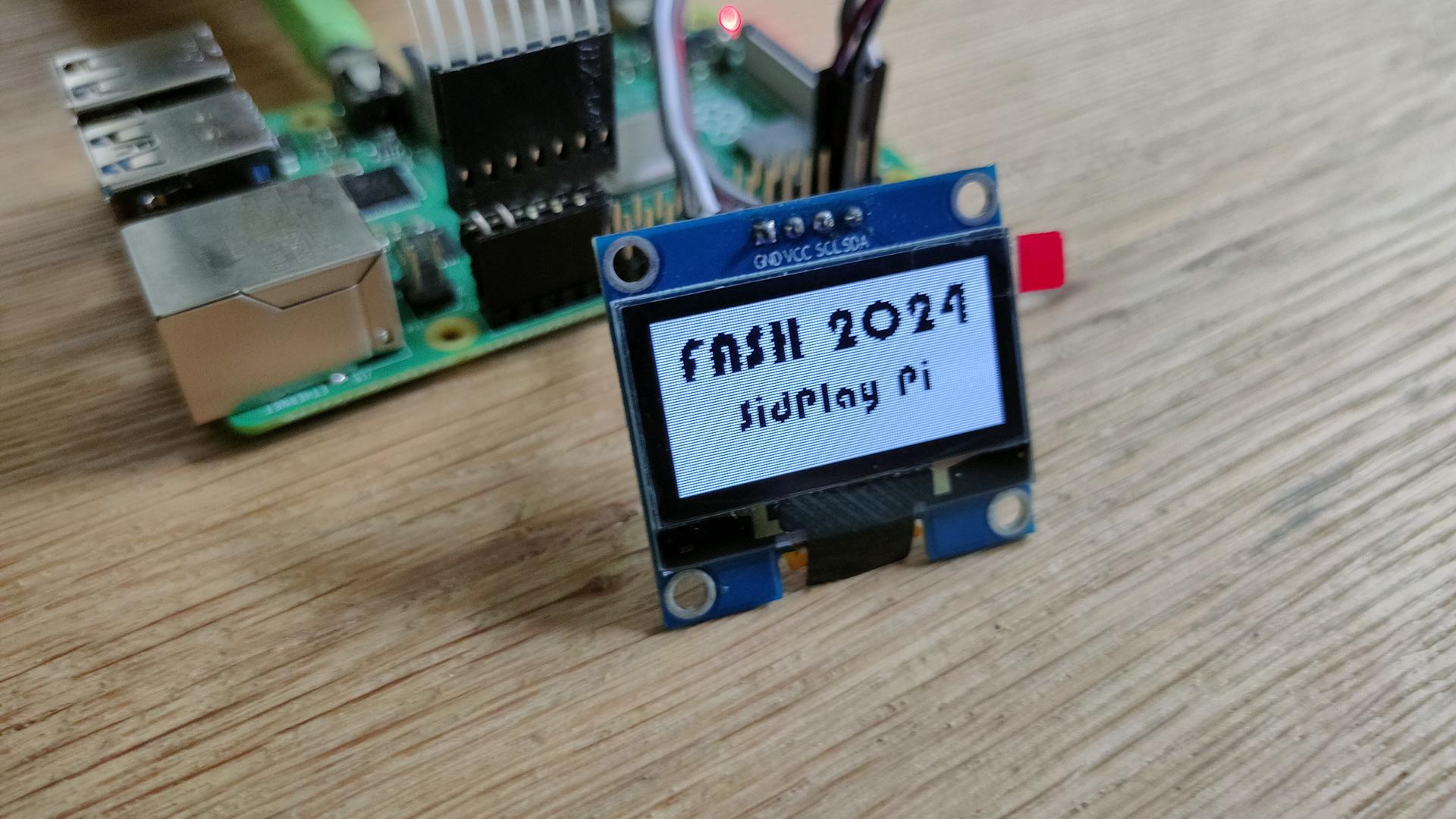
My Sidplayer as an option to select own collection. And I’ve made a top list
# Best composers (no order)
Ouwehand_Reyn
Tel_Jeroen
Huelsbeck_Chris
Rowlands_Steve
Hubbard_Rob
Daglish_Ben
Follin_Tim
Gray_Matt
Tjelta_Geir
Mibri (from get in the Van)

# Best tunes (no order)
R-Type.sid
Arkanoid.sid
Bottom.sid
Turbo_Outrun.sid
A_Tune_for_Unity.sid
Ohne_Dich_Rammstein.sid

# Start of own collection (not in above collection)
Abyssus_Ignis_[8580].sid
Catastrophe_[8580].sid
Dumb_Terminal_[8580].sid
Get_in_the_Van_[8580].sid
Getting_in_the_Van_[8580].sid
Supercharger_[8580].sid
Tuna_Guitar_[8580].sid
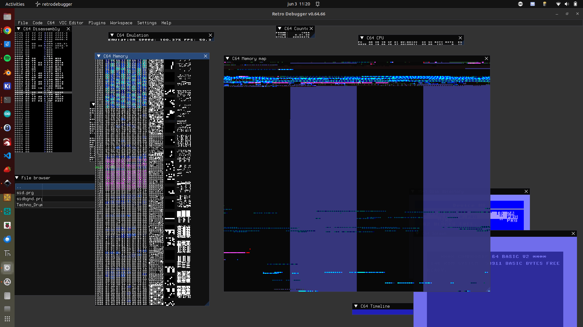
Investigating syncing effect to Sid music.
I got a great tip from Youth who made the Freakandel demo presented at X2024.
> Setup the loop to play the music

> Copy part of the memory to the screen ($0400) in the same loop to look for memory locations that are used as variables for the music. > Looking at

> Memory where the music is stored

> Zeropage ($00-$ff)

> See if there's some useful changes that coincide with for example drums

> For my own tunes, I use a music routine where I can put event markers in the music itself and react to those from the code. That's >how I synced https://www.micheldebree.nl/posts/big_angry_sprite/

> You could also try reading the SID registers for voice 3 (waveform and ADSR), those are the only ones that are not write-only. > Obviously you can then only react to those changes in voice 3.
I used retrodebugger to see which bytes are changing. Then I wrote a program which changes the background colour to this value. I also made a program to use a joystick to see which address have the most interesting effect. (use up)
!cpu 650rasterline
!to "borderflag.prg",cbm


* = $0801
    !byte $0d,$08,$dc,$07,$9e,$20,$34
    !byte $39,$31,$35,$32,$00,$00,$00

* = $c000
        sei                     ; turn off interrupts

        ldx #1                  ; enable raster interrupts
        stx $d01a

        lda #<irq       	; set raster interrupt vector
        ldx #>irq
        sta $0314
        stx $0315

        ldy #$f0                ; set first interrupt rasterline
        sty $d012
        lda $d011               ; reset rasterline hi bit
        and #%01111111
        sta $d011

        asl $d019               ; ack VIC interrupts
        cli

loop_until_doomsday
        jmp loop_until_doomsday

irq
	asl $d019       	; ack irq

	lda #$01		; set screenframe and background
	sta $d020
	lda #$02
	sta $d021

	lda #$38        	; wait for line $38
	cmp $d012
	bne *-3

	lda #$02		; set screenframe and background
	sta $d020
	lda #$01
	sta $d021

	lda #$f9        	; wait for line $f9C
	cmp $d012       	; just below border in 25 row mode
	bne *-3

	lda $d011       	; switch to 24 row mode ($d011 bit 3 = 0)
	and #$f7        	; %11110111
	sta $d011

	lda #$fd        	; wait for line $fd
	cmp $d012       	; just below border in 25 row mode
	bne *-3

	lda $d011       	; switch back to 25 row mode ($d011 bit 3 = 1)
	ora #$08        	; %00001000
	sta $d011

	jmp $ea31		; exit irq