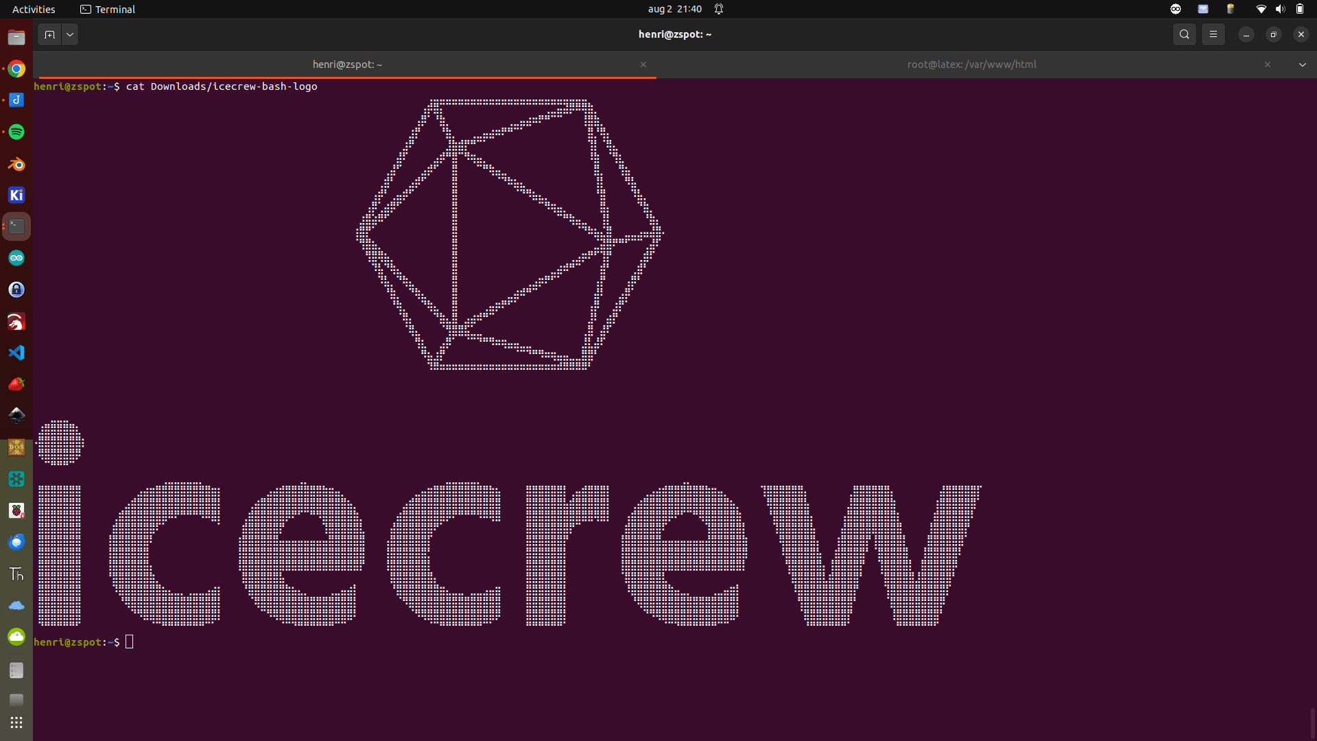
Cool bash banner
While attending Bornhack 2024 in Danmark, I came up with the below fun ideas.
Using Python and OpenCV, I made some funny webcam hacks.
Note: My laptop webcam is very bad, a better webcam should give you a more stable result.
First, a virtual workspace flipper. Just using my head movement to flip through my virtual desktops. (Turning left and right)
Next, an image viewer.
Using your head movement up, down, left and right to control the image.
Note : this is not the same movement as above. This won’t use rotation of your head!
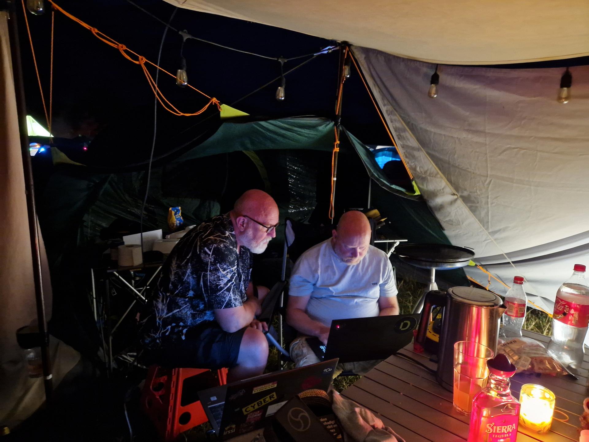
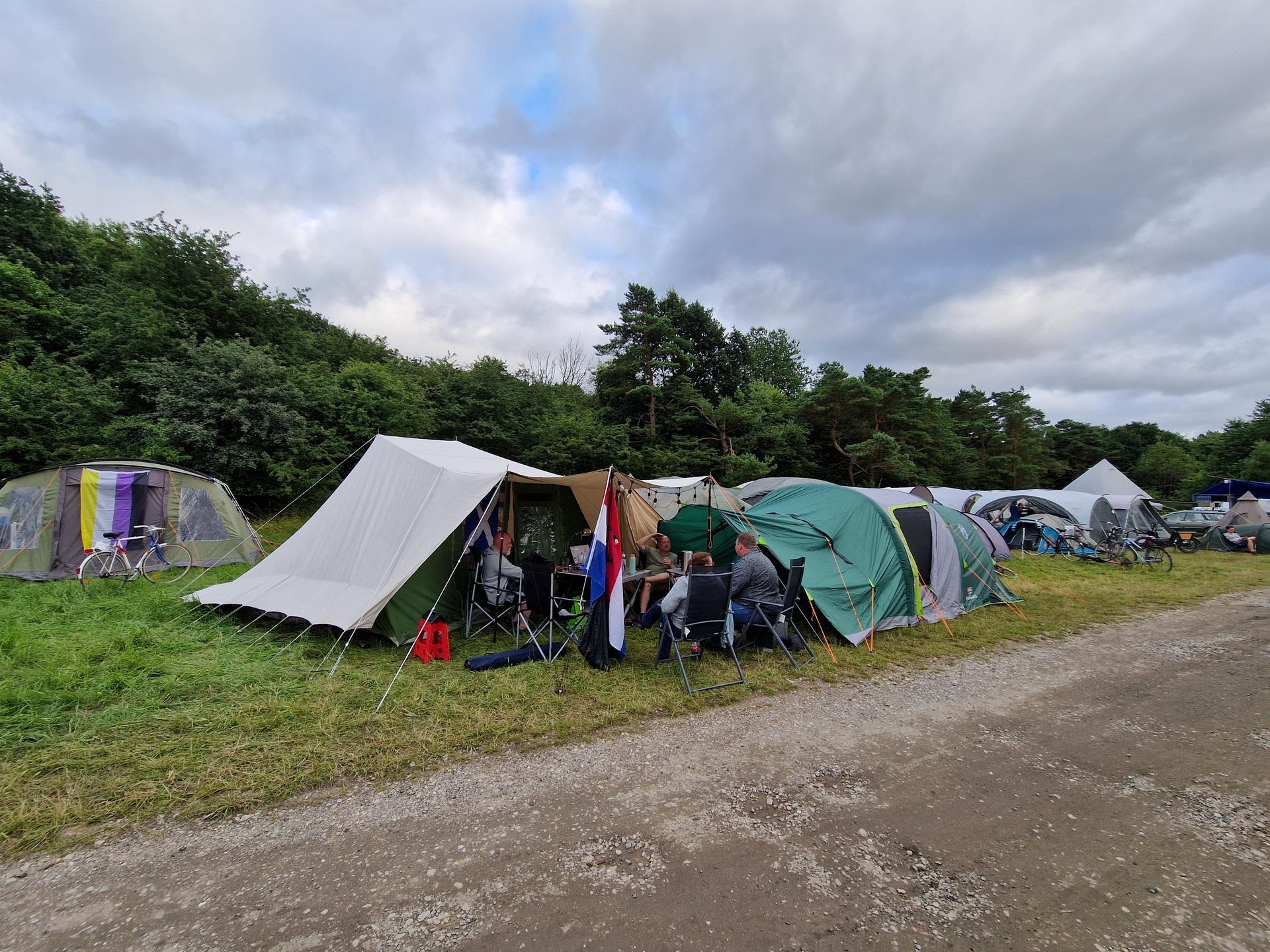
The 15th, we got in our car and drove to Denmark.
We went to Bornhack2024, a hackers camp.
Although there are bad hackers (black hat), the term hacker is being used to describe people who are using technology alternative or even hack food and drinks.
Create something new or improve. Mostly using computers, but think of it in a broad way.
Programming, 3D designing or printing. Learning new things.
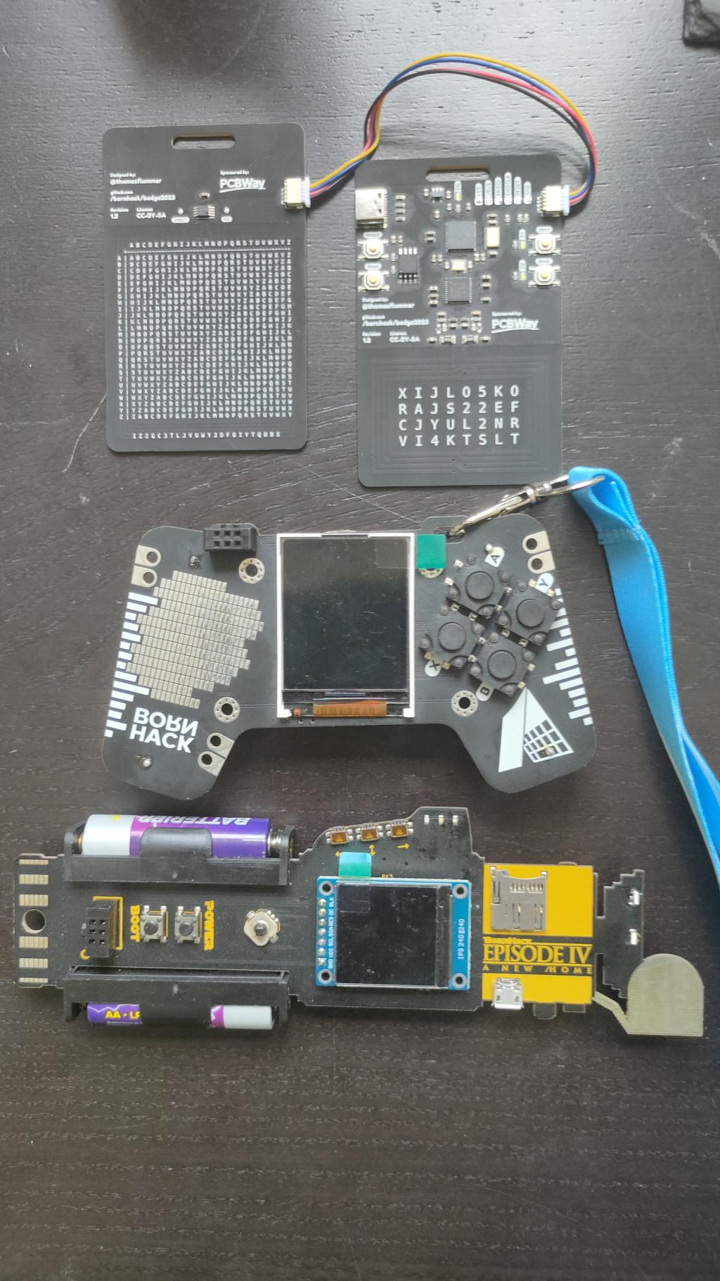
We (me and my girlfriend) went with Bigred (and his girlfriend) and Tyrone. Both good old friends.
With Bigred I made a mini C64 Badge in the last few months.
With Tyrone I started coding 6502 Machine Language again.
(Planning to release a demo at X2025)
Stuff I did there:
After a week of hacking, we went for a short holiday in Denmark.
Visiting Viking Museums, Old cosy towns, WWII bunkers, the Beach and more.
Driving back to the Netherlands, we visited the only surviving VII-C U-boat in the world.
(Same as I 3D printed for the Uboot game)


Started coding a demo with a friend of mine.
I made a part that uses raster interrupts and gives the illusion that the picture is up in the border.
Hopefully I’ve got some rastertime left to play music. But I learned a lot!
UPDATE: Yes also with SID music!
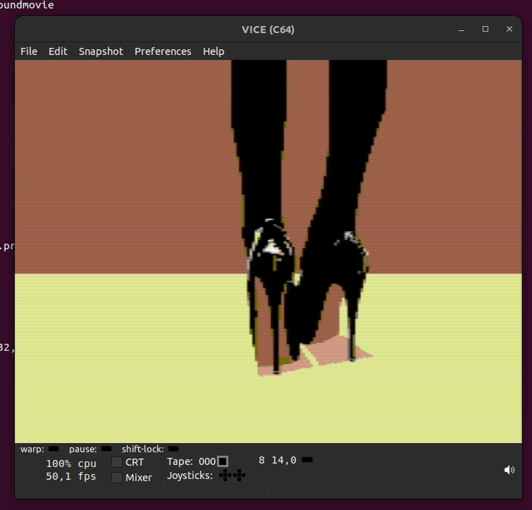
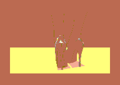


Not shown: Bad raster lines, split colors background and bordercolor.
Maybe I’ll add these later.
UPDATE: 20240720
Sprite multiplexing done and self modifying code.
But it works! Many iterations .. almost perfect
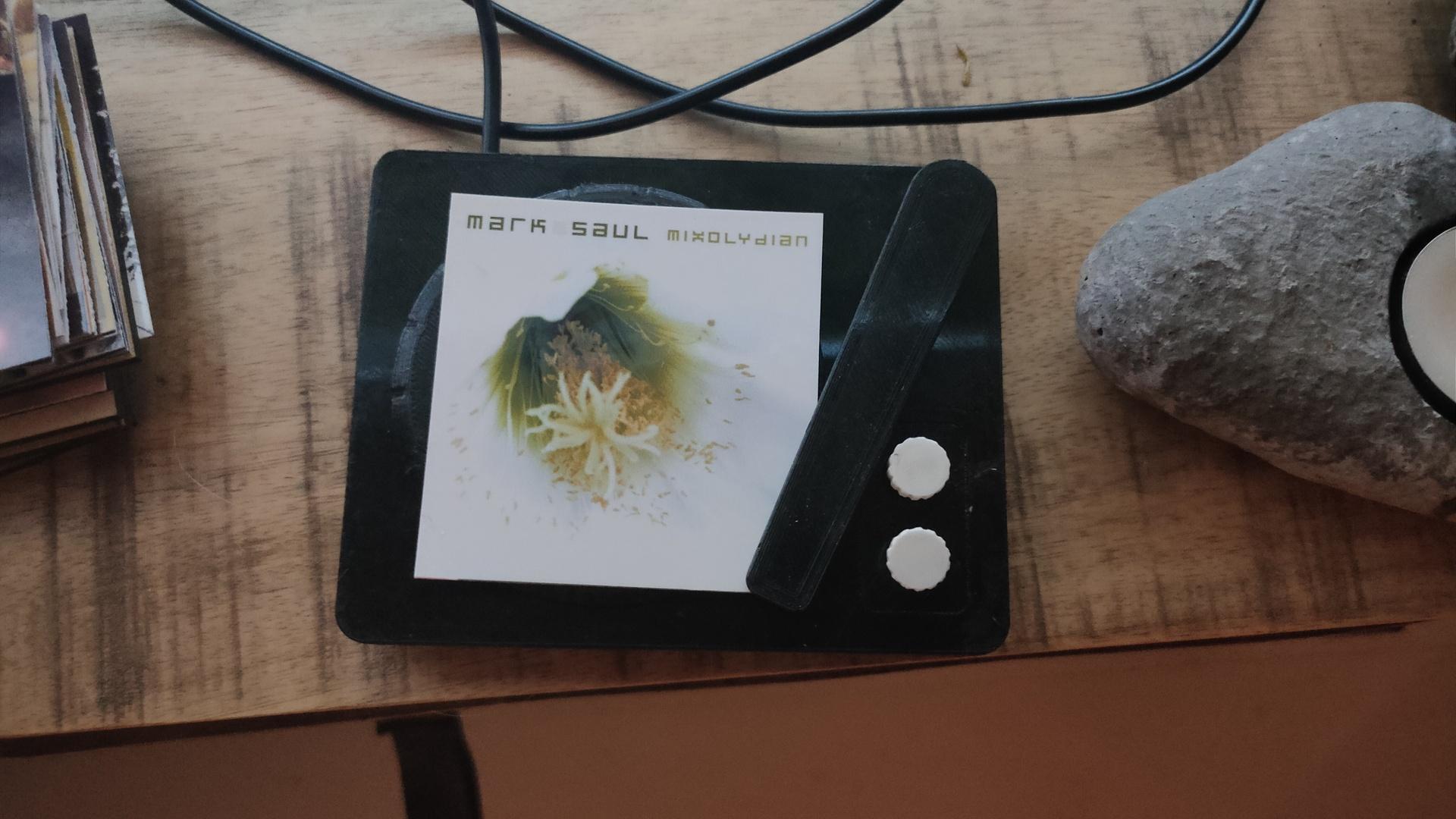
Record player is going to be re-printed at a higher quality.
Updated python client (see previous posts)
import paho.mqtt.client as mqtt
import urllib.request
from time import sleep

def on_connect(client, userdata, flags, rc):  # The callback for when the client connects to the broker
        print("Connected with result code {0}".format(str(rc)))
        client.subscribe("spotify/rfid/idlms")
        client.subscribe("spotify/rfid/but1")
        client.subscribe("spotify/rfid/but2")
        client.subscribe("spotify/rfid/arm")

def on_message(client, userdata, msg):  # The callback for when a PUBLISH message is received from the server.
        print("Message received-> " + msg.topic + " " + str(msg.payload))  # Print a received msg
        if msg.topic == "spotify/rfid/idlms":
            urllib.request.urlopen("http://LMS-SERVER-IP:9000/anyurl?p0=playlistcontrol&p1=album_id:" + msg.payload.decode() + "&p2=cmd:load&player=00:04:20:16:d9:04")
        if msg.topic == "spotify/rfid/but1":
            urllib.request.urlopen("http://LMS-SERVER-IP:9000/anyurl?p0=pause&player=00:04:20:16:d9:04")
            sleep(1)
        if msg.topic == "spotify/rfid/but2":
            urllib.request.urlopen("http://LMS-SERVER-IP:9000/anyurl?p0=pause&pt=1&player=00:04:20:16:d9:04")
            sleep(1)
        if msg.topic == "spotify/rfid/arm":
            urllib.request.urlopen("http://LMS-SERVER-IP:9000/status.html?p0=button&p1=jump_fwd&player=00:04:20:16:d9:04")
            sleep(1)

client = mqtt.Client("lmsclient")  # Create instance of client with client ID “digi_mqtt_test”
client.on_connect = on_connect  # Define callback function for successful connection
client.on_message = on_message  # Define callback function for receipt of a message
client.connect('MQTTSERVER', 1883)
client.loop_forever()  # Start daemon
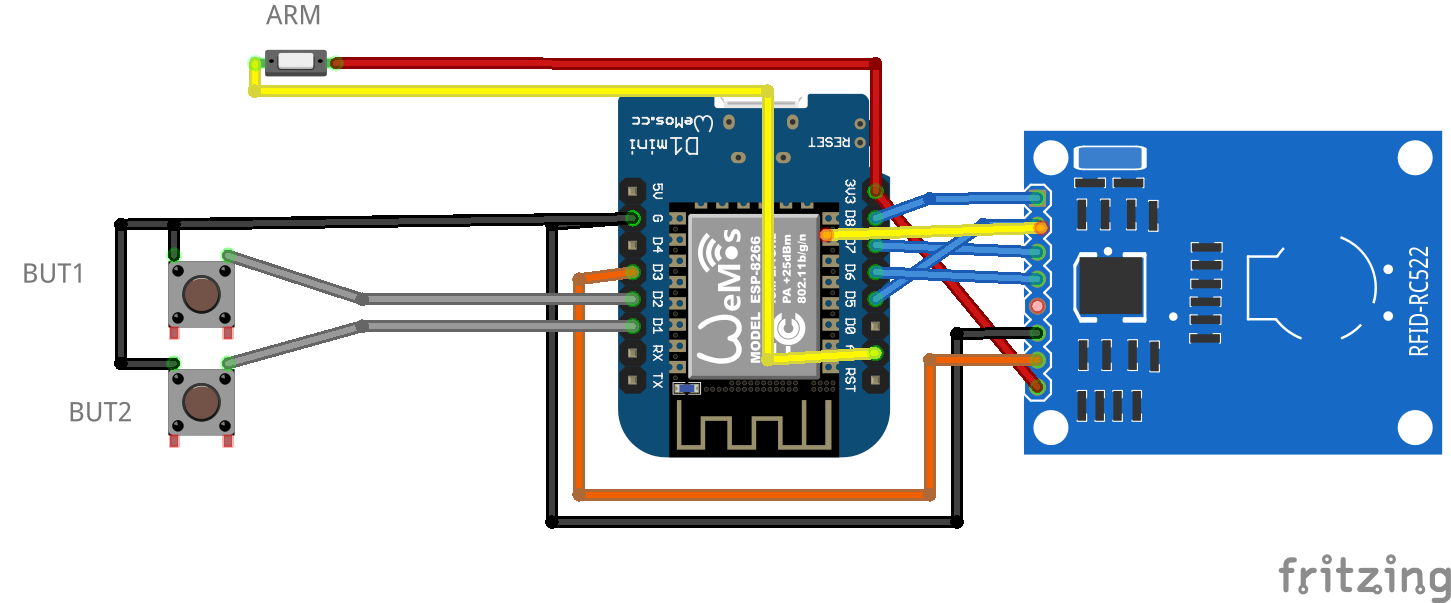
Wemos INO file
#include <Arduino.h>
#include <SPI.h>
#include <MFRC522.h>
#include <ESP8266WiFi.h>
#include <WiFiClient.h>
#include <PubSubClient.h>
#define SS_PIN 15
#define RST_PIN 0

const int buttonPin1 = D1;
const int buttonPin2 = D2;

int buttonState1 = 0;
int buttonState2 = 0;

MFRC522 mfrc522(SS_PIN, RST_PIN);
  MFRC522::StatusCode status; //variable to get card status

  byte buffer[18];  //data transfer buffer (16+2 bytes data+CRC)
  byte size = sizeof(buffer);

  uint8_t pageAddr = 0x06;  //In this example we will write/read 16 bytes (page 6,7,8 and 9).
                            //Ultraligth mem = 16 pages. 4 bytes per page.
                            //Pages 0 to 4 are for special functions.

unsigned long cardId = 0;
WiFiClient net;
PubSubClient client(net);
const char* mqtt_server = "MQTTBROKER";
const char* ssid = "MYSSID";
const char* password = "MYWIFIPASWORD";
String topicStr = "";
byte buffer2[8];

boolean Rflag=false;
int r_len;
char payload[5];
byte value[5];
void setup() {
  Serial.begin(9600);
    pinMode(buttonPin1, INPUT_PULLUP);
    pinMode(buttonPin2, INPUT_PULLUP  );

  SPI.begin();
  mfrc522.PCD_Init();
  WiFi.mode(WIFI_AP_STA);
  WiFi.begin(ssid, password);
  client.setServer(mqtt_server, 1883);
     delay(100);
    client.setCallback(callback);
      delay(100);
    client.subscribe("spotify/rfid/in/#");
}
void reconnect() {
  while (WiFi.waitForConnectResult() != WL_CONNECTED) {
  }
  while (!client.connected()) {
    String clientId = "rfid-";
    clientId += String(random(0xffff), HEX);
    if (!client.connect(clientId.c_str(), "rfidclient", "...")) {
      delay(5000);
    }
  }
  client.subscribe("spotify/rfid/in/#");
}
void callback(char* topic, byte* payload, unsigned int length) {
  Serial.print(F("Called"));
   Rflag=true; //will use in main loop
   r_len=length; //will use in main loop
   int j=0;
     for (j;j<length;j++) {
       buffer2[j]=payload[j];
       //Serial.print((char)payload[j]);
       }
if (r_len < 3) {
  Rflag=false;
  Serial.print(F("Set false"));
}
buffer2[j]='\0'; //terminate string
}

void loop() {
    if (!client.connected()) {
    reconnect();
  }

buttonState1 = digitalRead(buttonPin1);
  //Serial.print(buttonState1);
  if (buttonState1 == 0 ) {
    client.publish("spotify/rfid/but1", "0");
  }
buttonState2 = digitalRead(buttonPin2);
  //Serial.println(buttonState2);
  if (buttonState2 == 0 ) {
    client.publish("spotify/rfid/but2", "0");
  }

int reading = analogRead(0);
  //Serial.println(reading);
  if (reading > 500 ) {
    client.publish("spotify/rfid/arm", "0");
  }

  client.loop();
  if (!mfrc522.PICC_IsNewCardPresent()) {
    return;
  }
  if (!mfrc522.PICC_ReadCardSerial()) {
    return;
  }
if (Rflag) {
        for (int i=0; i < 4; i++) {
    //data is writen in blocks of 4 bytes (4 bytes per page)
    status = (MFRC522::StatusCode) mfrc522.MIFARE_Ultralight_Write(pageAddr+i, &buffer2[i*4], 4);
    if (status != MFRC522::STATUS_OK) {
      return;
    }

  }
  Rflag=false;
}

  cardId = getCardId();
  char buffer3[10];
  sprintf(buffer3, "%lu", cardId);
  client.publish("spotify/rfid/id", buffer3);

  status = (MFRC522::StatusCode) mfrc522.MIFARE_Read(pageAddr, buffer, &size);
  if (status != MFRC522::STATUS_OK) {
    Serial.println(F("MIFARE_Read() failed: (R)"));
    Serial.println(mfrc522.GetStatusCodeName(status));
    return;
  }

  Serial.println(F("Read data: "));
  for (byte i = 0; i < 5; i++) {
    Serial.write(buffer[i]);
       buffer2[i]=buffer[i];
    }

  client.publish("spotify/rfid/idlms", buffer,5);
  delay(1000);
  mfrc522.PICC_HaltA();
}

unsigned long getCardId() {
  byte readCard[4];
  for (int i = 0; i < 4; i++) {
    readCard[i] = mfrc522.uid.uidByte[i];
  }
  return (unsigned long)readCard[0] << 24
    | (unsigned long)readCard[1] << 16
    | (unsigned long)readCard[2] << 8
    | (unsigned long)readCard[3];
}
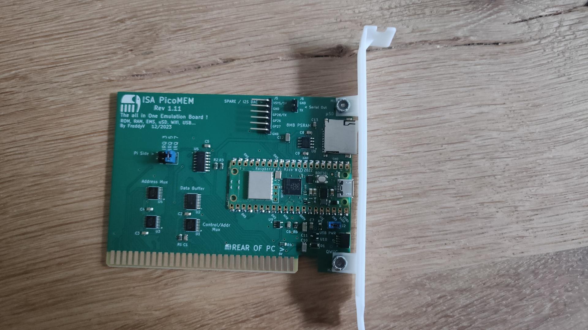
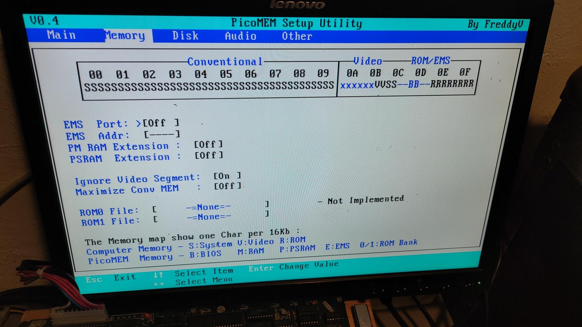
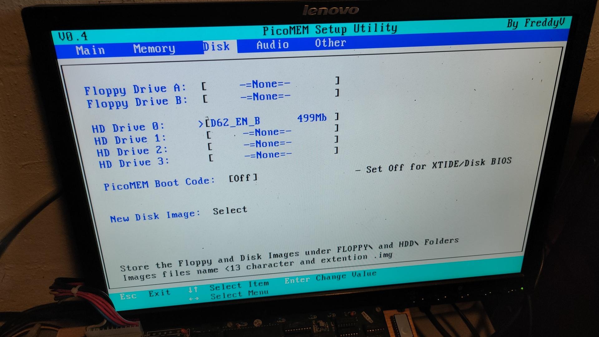
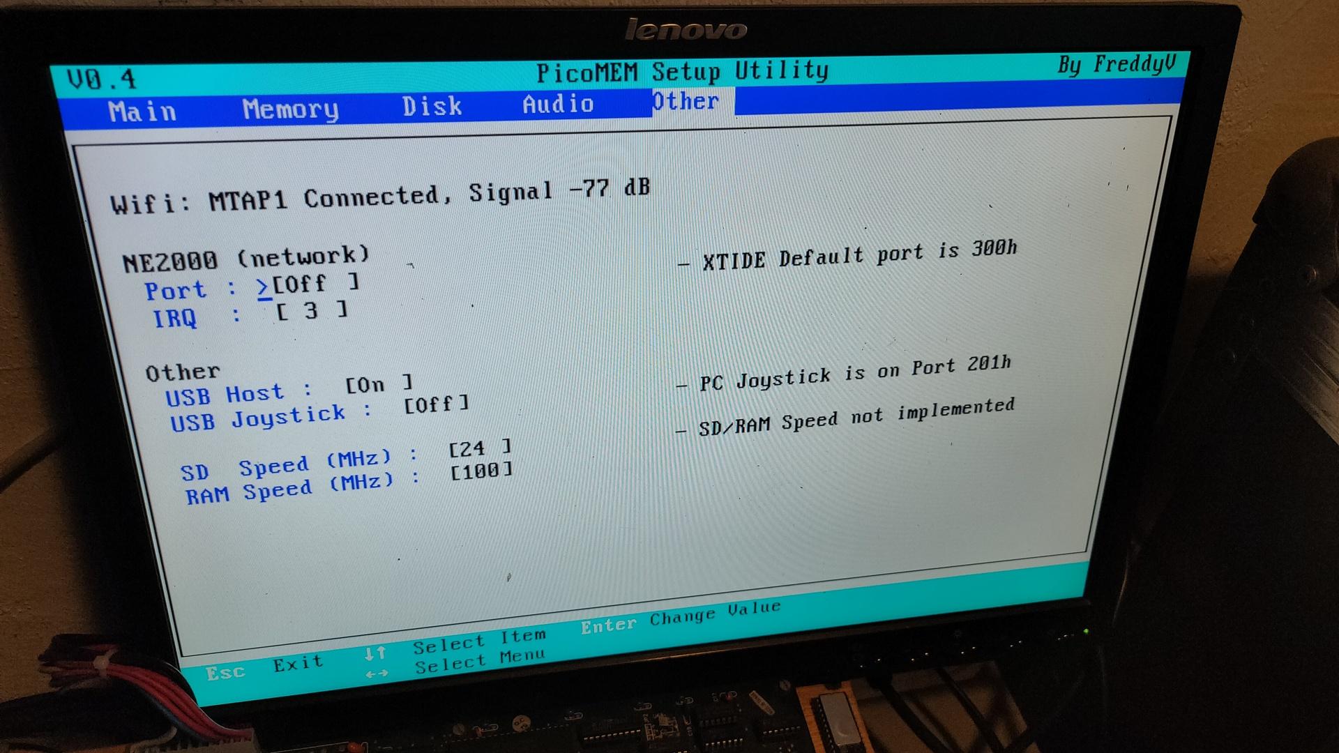
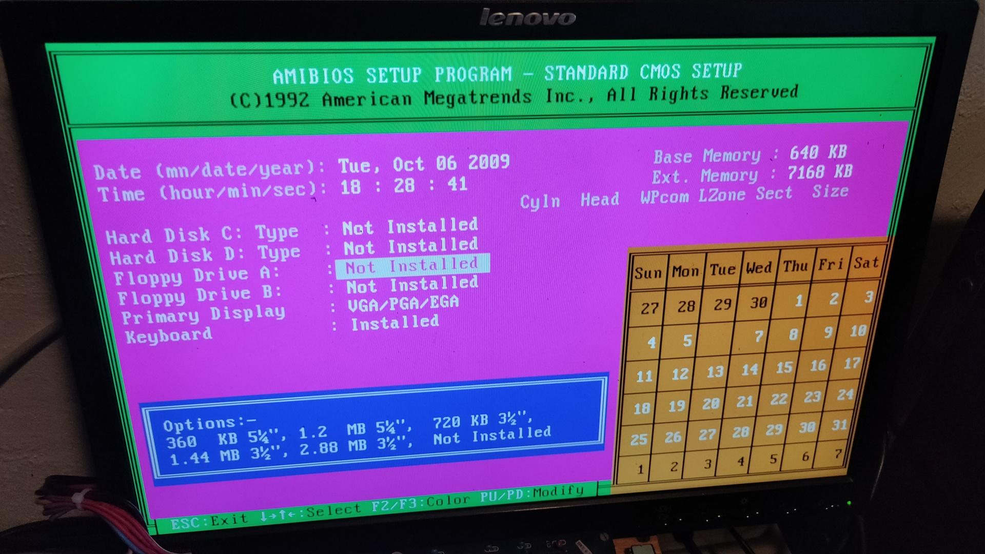
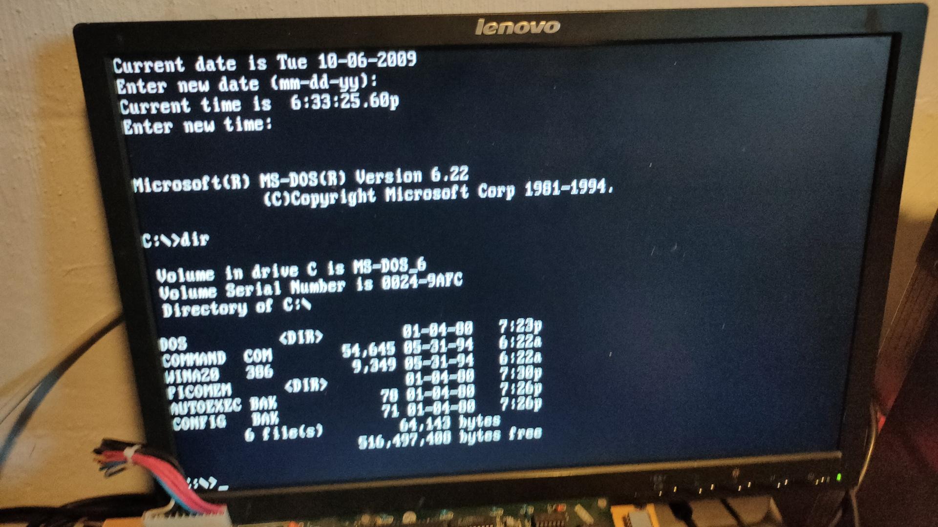
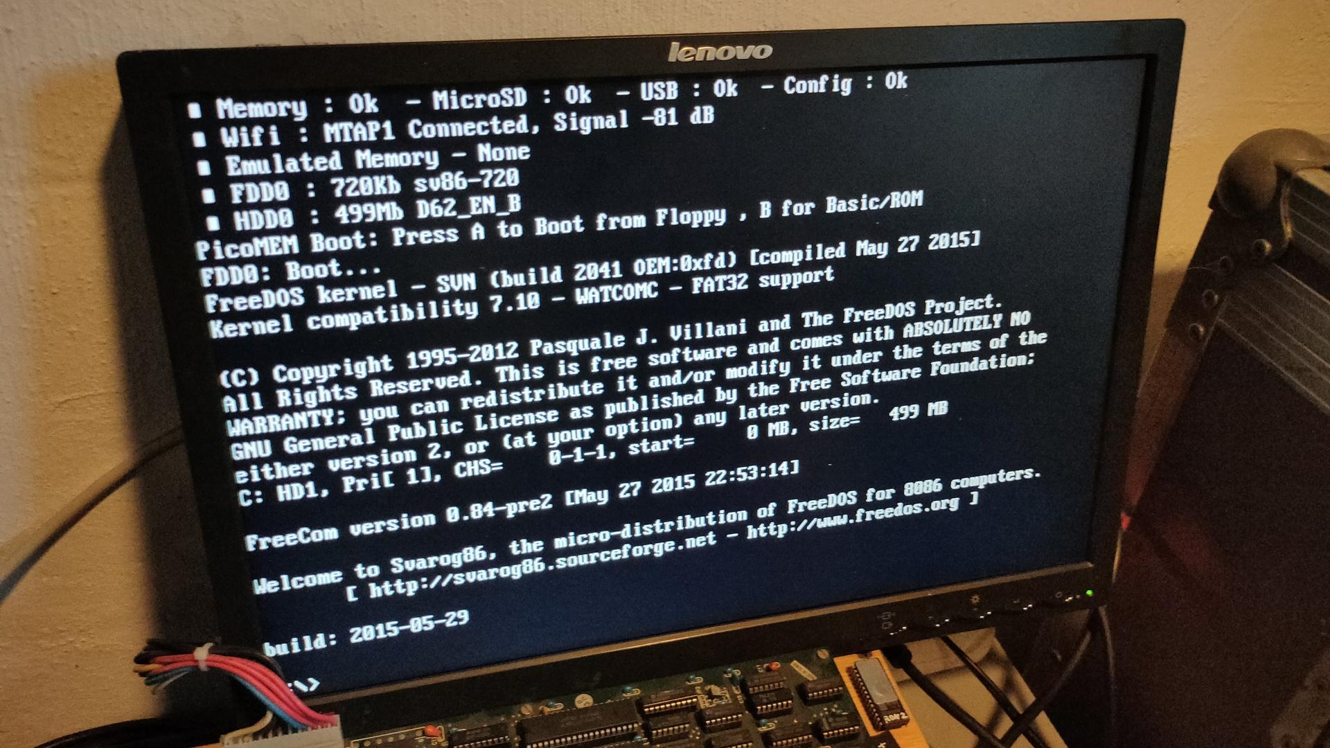
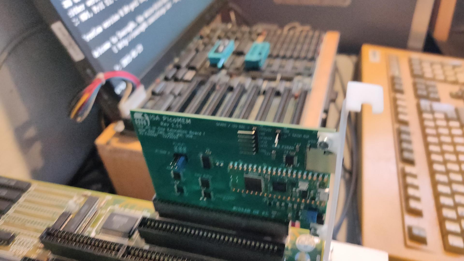
https://github.com/FreddyVRetro/ISA-PicoMEM
Awesome device
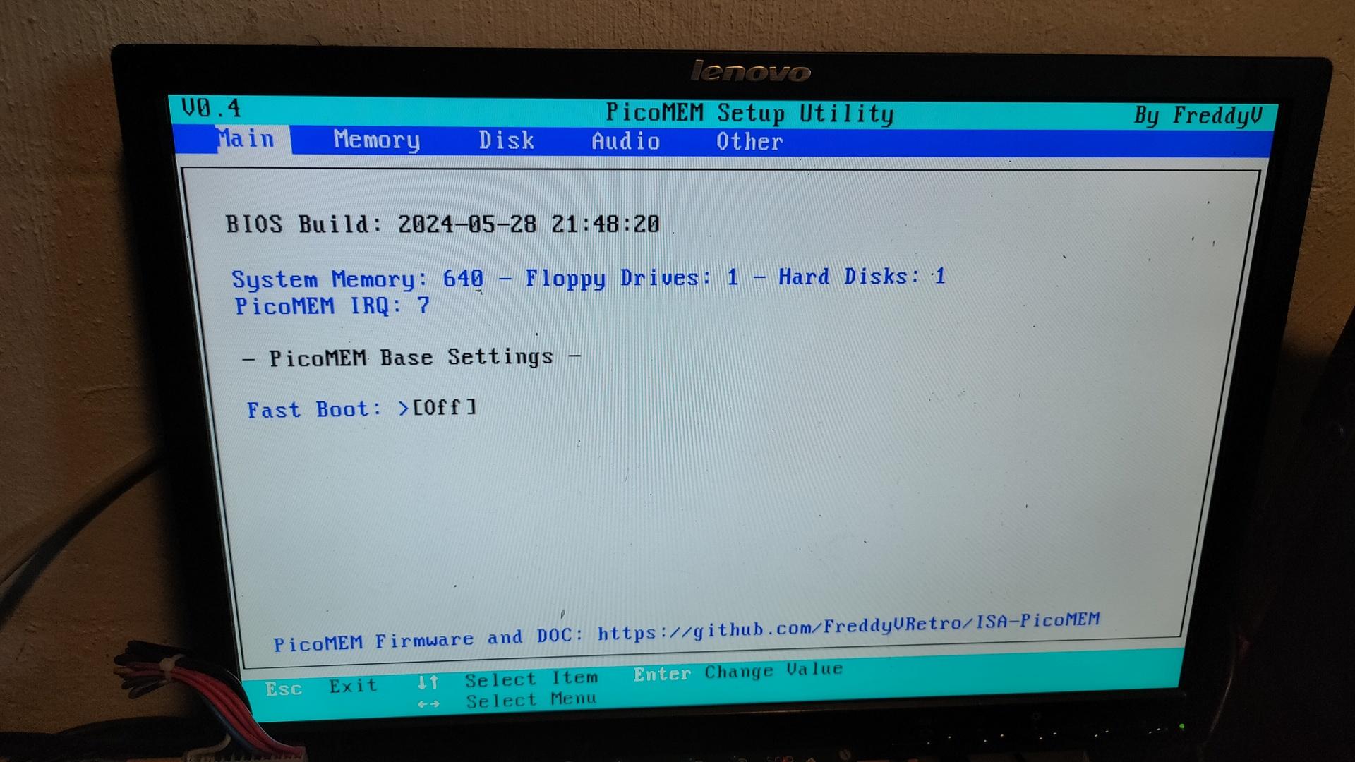
Some other screen captures
I’ve connected the rotary encoder directly to the zero.
Although many websites state that you need pull-up resistors, there is no need. Just use the internal pull-up resistors in the Pi.
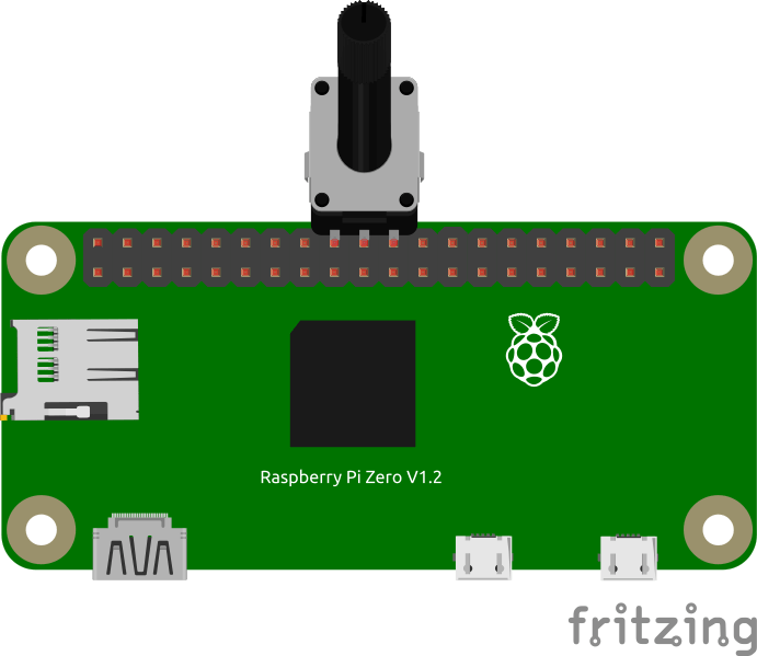
Example code
        GPIO.setmode(GPIO.BCM)					# Use BCM mode
        GPIO.setup(self.24, GPIO.IN, pull_up_down=GPIO.PUD_UP)
        GPIO.setup(self.25, GPIO.IN, pull_up_down=GPIO.PUD_UP)
NOTE: Between 24 and 25 is a GND connection
Besides USB HID below XT, C64 and Amiga connectors will be emulated
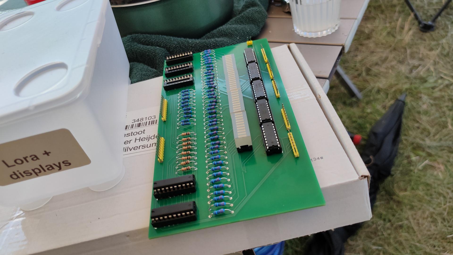
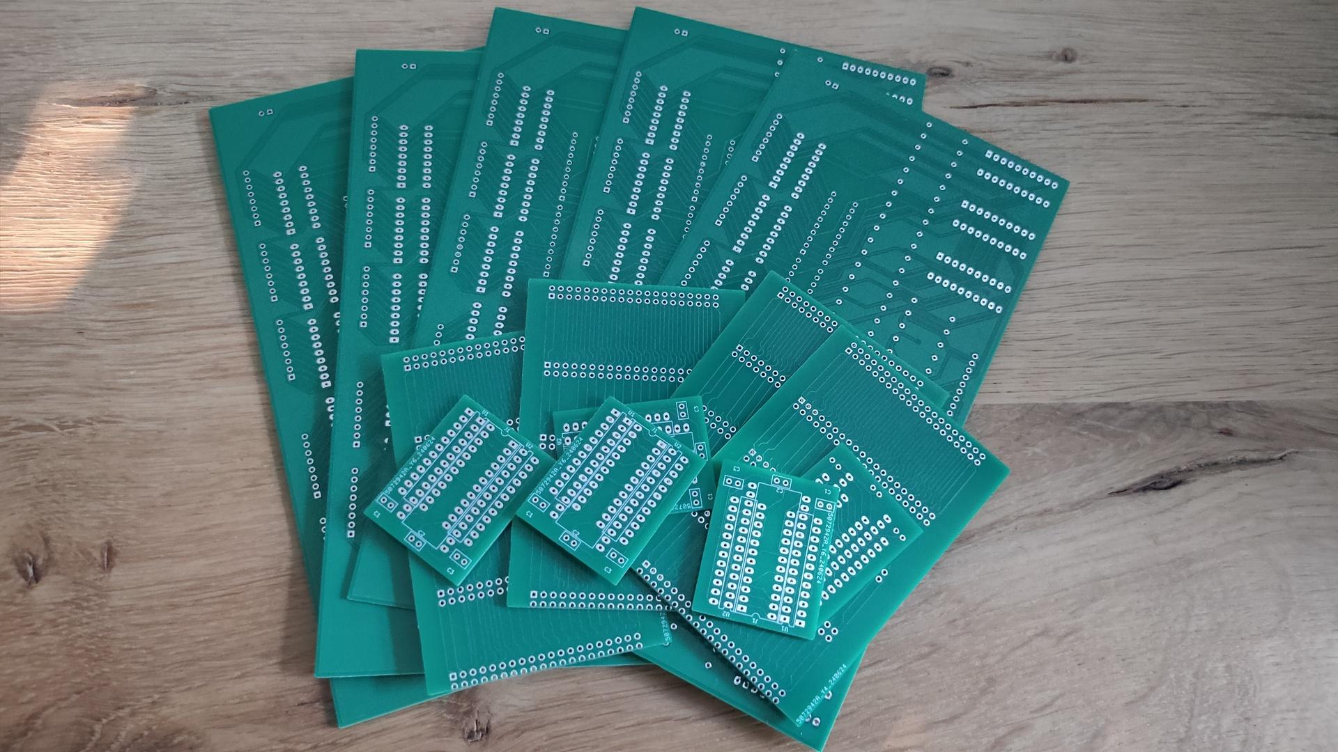
Got my new PCBs in.
My Bus Manipulator, Backplane for 6502, and C64 PLA replacement.
I’m selling the leftover PCBs if you are interested.
These are not the final versions.
They should work, but they lack holes for stand-offs or feet.
Example setups for the backplane.
Using a flatcable or direct connection to my 6502 SBC.
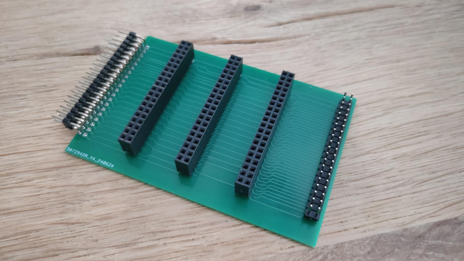
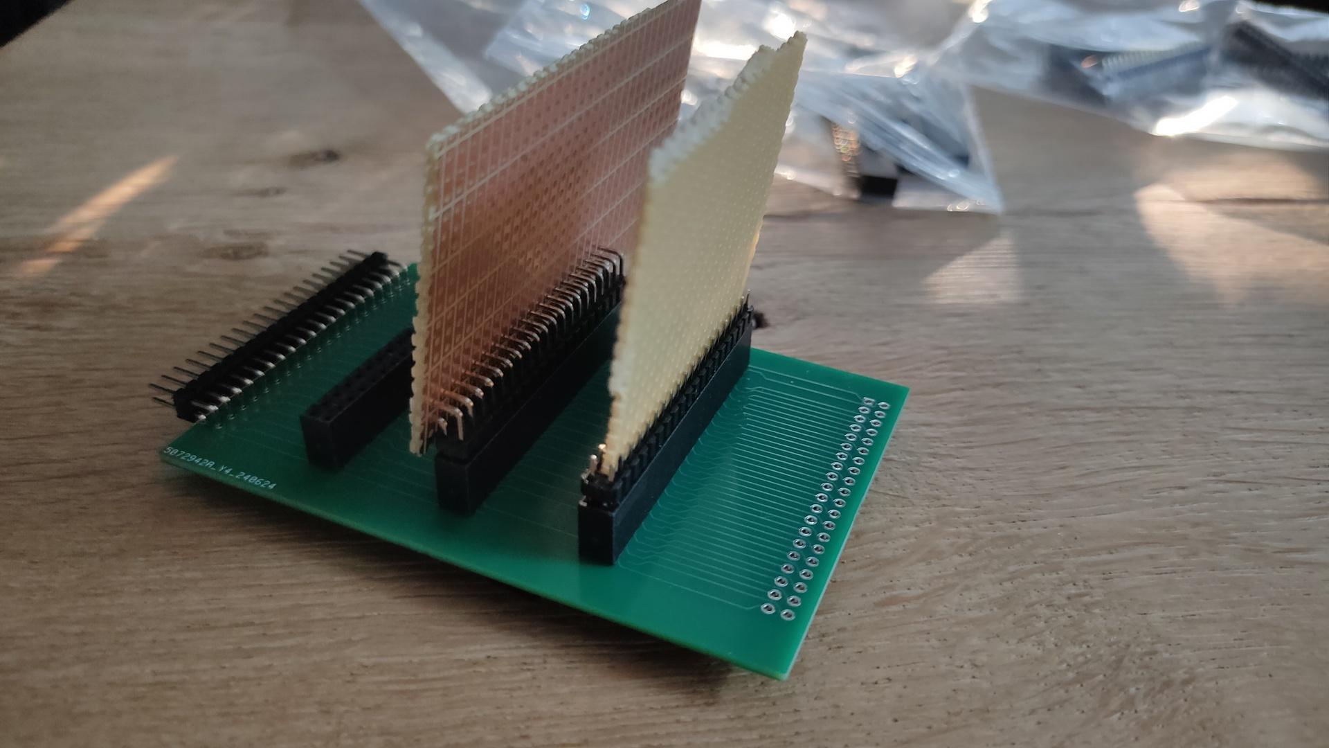
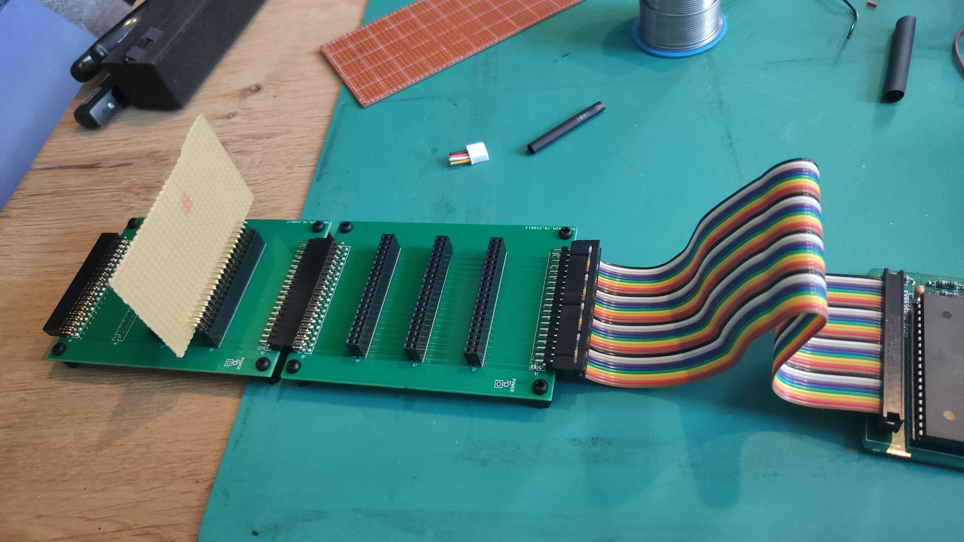
The backplane was designed to be chained together.
(Horizontal female – male connection)
The vertical cards I’ve planned to make are:
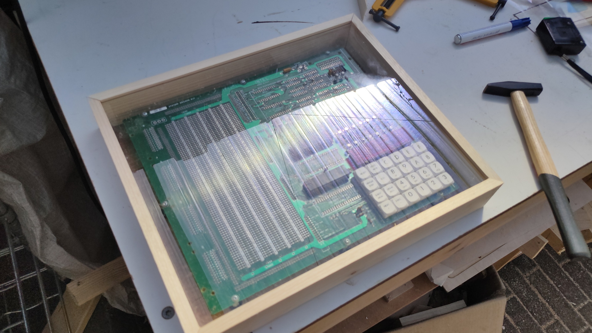
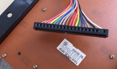
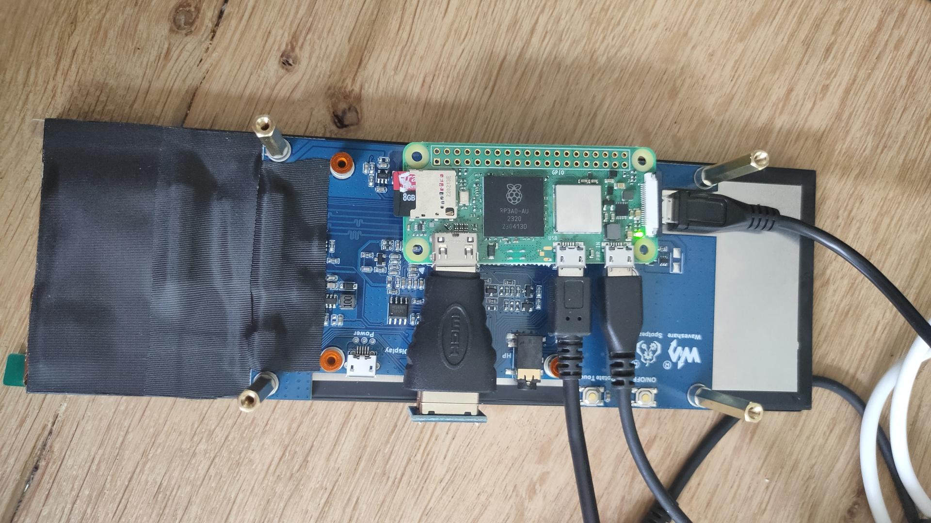
Testing the first keyboard. It is the 8085-SDK hex matrix keyboard.
It is running on a Raspberry Pi Zero 2, without X server.
So the images are displayed using the framebuffer.
Also the touch data is read using evdev and the raw devices.
Todo:
Bash test and configuring the OS for testing.
cat <<EOF >> /boot/config.txt
hdmi_group=2
hdmi_mode=87
hdmi_timings=400 0 100 10 140 1280 10 20 20 2 0 0 0 60 0 43000000 3
display_rotate=3
EOF

# Image testing
apt-get install fbi
sudo fbi -d /dev/fb0 -T 1 8085.png  -a --noverbose

apt-get install python3-evdev python3-uinput evtest
evtest
First simple python test
import select
from math import floor
import sys
slot = 0

keysname=[["F","E","D","C","vect-int","reset"],
          ["B","A","9","8","GO","Single-Step"],
          ["7","6","5","4","Exam-reg","Subst-mem"],
          ["3","2","1","0","Exec","Next"],
          ]
keysnames=[["F","E","D","C","vect-int","reset"],
          ["B","A","L","H","GO","Single-Step"],
          ["PCL","PCH","SPL","SPH","Exam-reg","Subst-mem"],
          ["3","2","1","0",".",","],
          ]

for path in evdev.list_devices():
    device = evdev.InputDevice(path)
    if evdev.ecodes.EV_ABS in device.capabilities():
        break
else:
    sys.stderr.write('Failed to find the touchscreen.\n')
    sys.exit(1)

while True:
    r, w, x = select.select([device.fd], [], [])

    id_ = -1
    x = y = 0

    for event in device.read():

        if event.code == event.value == 0:
           if id_ != -1:
                yy = floor(( x - 600 ) / 700)
                xx = floor(( y - 1377 ) / 226)
                if yy < 4 and yy >=0 and xx < 6 and xx >= 00:
                     if slot == 1:
                         print(keysnames[yy][xx])
                     else:
                         print(keysname[yy][xx])

        elif event.code == ABS_MT_TRACKING_ID:
            id_ = event.value
        elif event.code == ABS_MT_SLOT:
            slot = event.value
        elif event.code == ABS_MT_POSITION_X:
            x = event.value
        elif event.code == ABS_MT_POSITION_Y:
            y = event.value
I came up with a simple matrix calculation
Pressing the 4 corner keys gave me x and y.
I took averages for min and max reading.
I don’t need pixel-perfect reading, and I noticed values between 960 and 3080 vertically.
We want 960 – 3080 into 4 blocks, but the middle should start @ 960.
So 3080/3 = about 700
700 / 2 = 350
block 1 starts 350 sooner than 960 is ~ 600
Upper key y coords = 600-> + 700
Next is 1300 -> + 700
converting to whole numbers using floor gives me:
floor(( y – 600 ) / 700)
NOTE: My x and y are rotated
Example using coordinates
1600, 1600
floor(( 1600 – 600 ) / 700) = floor(1,4…) = 1st row
(from row 0,1,2,3)
I’ve been busy programming Python and NodeRed for a client.
But these are the things I’ve done in the last days.
C64 Assembly:
Breaking borders, using sprites and multicolor font intro.

It does not look impressive, but I’ve learned a lot.
Found a new way (for me) to open borders and change border colours on predefined raster lines.
Sources will be posted.
KiCad tutorial, posted on YT also because I could not find many resources about the subject online. Maybe it’s helpful
Video editing using Kdenlive.
Edit: Even faster, use Netlabels, no need to join pins.
Press L (uppercase) select pin 1, name 1.
Press and hold insert until all pins named.
Copy paste socket 5 times and goto your PCB tab.
This movie is about creating a backplane for a 6502 SBC I’m building.
It is real-time and below 4 minutes.
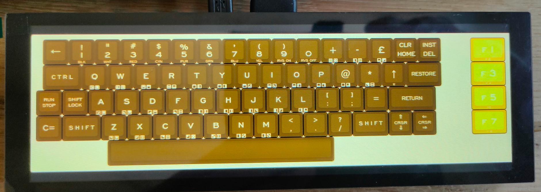
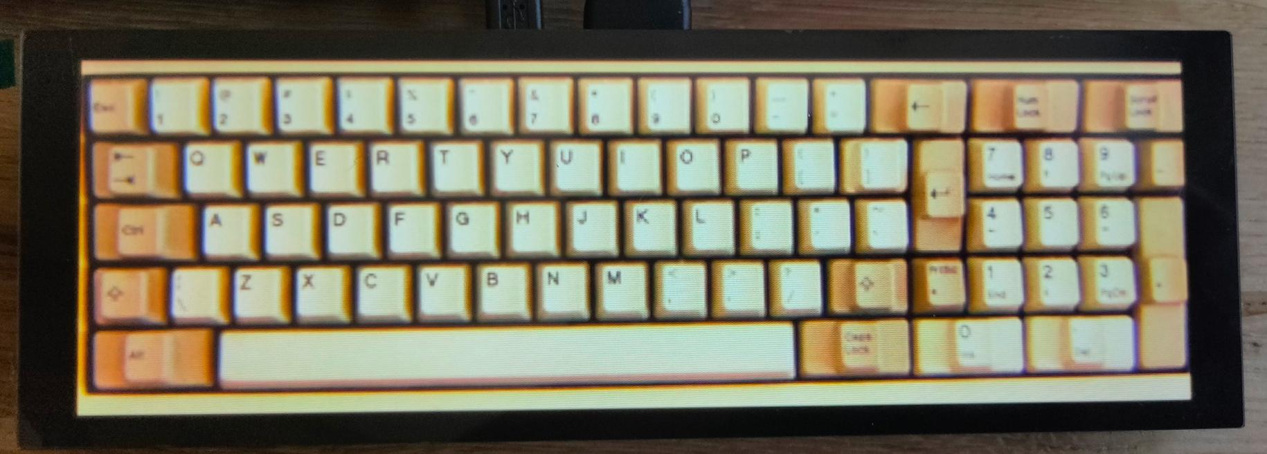
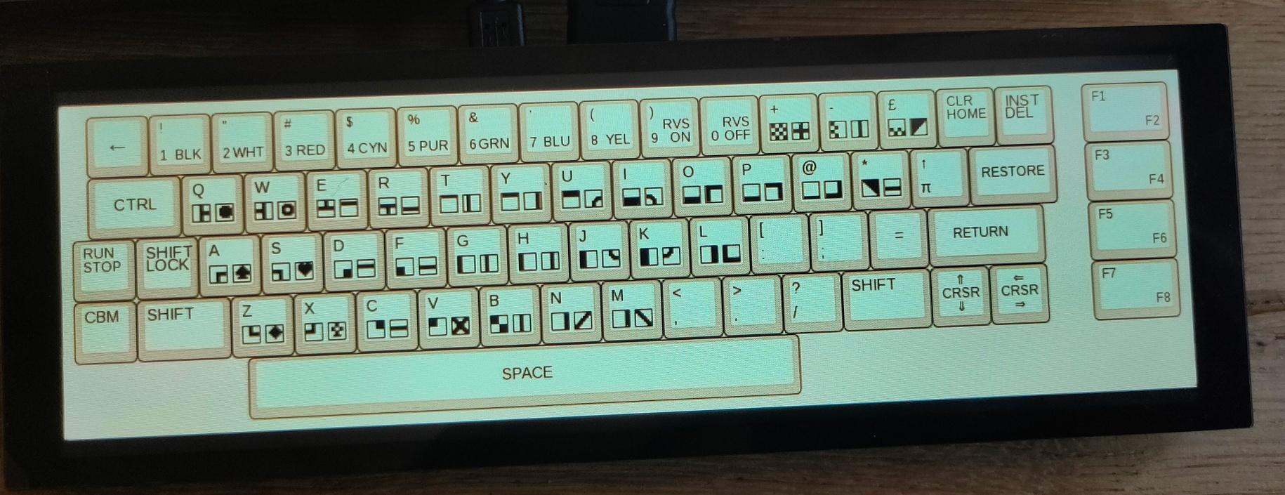
Multi Keyboard
My small multitouch screen came in.
This is for my previously mentioned multi-computer case.
It is going to show multiple keyboard layouts for different systems.
(See previous posts about this)
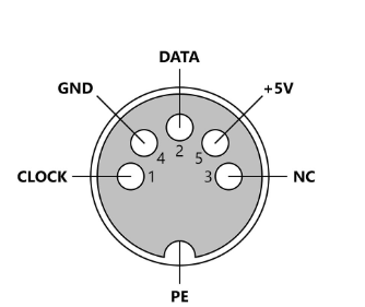
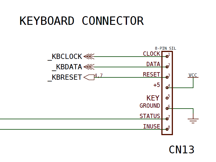
Waveshare display, Raspberry Zero as HID device, using USB and pin emulated keyboards. (c64 matrix, AT (DIN) keyboard, ps2 keyboard)
Some example screens
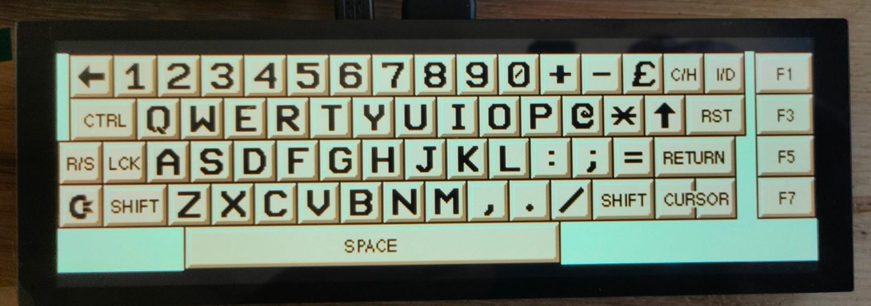
I’m also going to make a layout like the keyboards on my 8085