While I made this for my Commodore C64, it is applicable for many things.
It started with some cheap displays from Ali, and some leftover Wemos D1 from my Pressure Lab project.
I Started measuring the audio output from sound devices and from my C64. I soon discovered that I needed some way to get the offset and amplification correct for the analogue input of a Wemos. (0-3v3)
So a little op-amp circuit was born, but not without some struggles. I forgot many things about amplifiers. It was one of the first school books I got rid of. (Sorry mister Rafaela)
After searching the internet and posting a question on Reddit I ended up with the following.
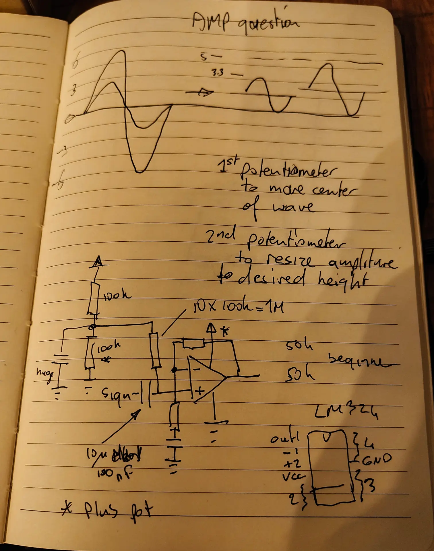
R1 and R2 are 100M. The potentiometer P1 allows me to set the offset. R3 is 1M C1 is 100nF to decouple the audio signal from the RCA.
R4 is 47K and C2 is 330nF (thanks tycho205) Cimportant=1/(2πfR2) where f is the lowest frequency of interest. In this case Cimportant should be about 330nF
LM324 is a quad amplifier, leftover from another project. Note, the SINGLE RAIL power.
P2 potentiometer is 2M (leftover) and gives me a variable amplifying opportunity.
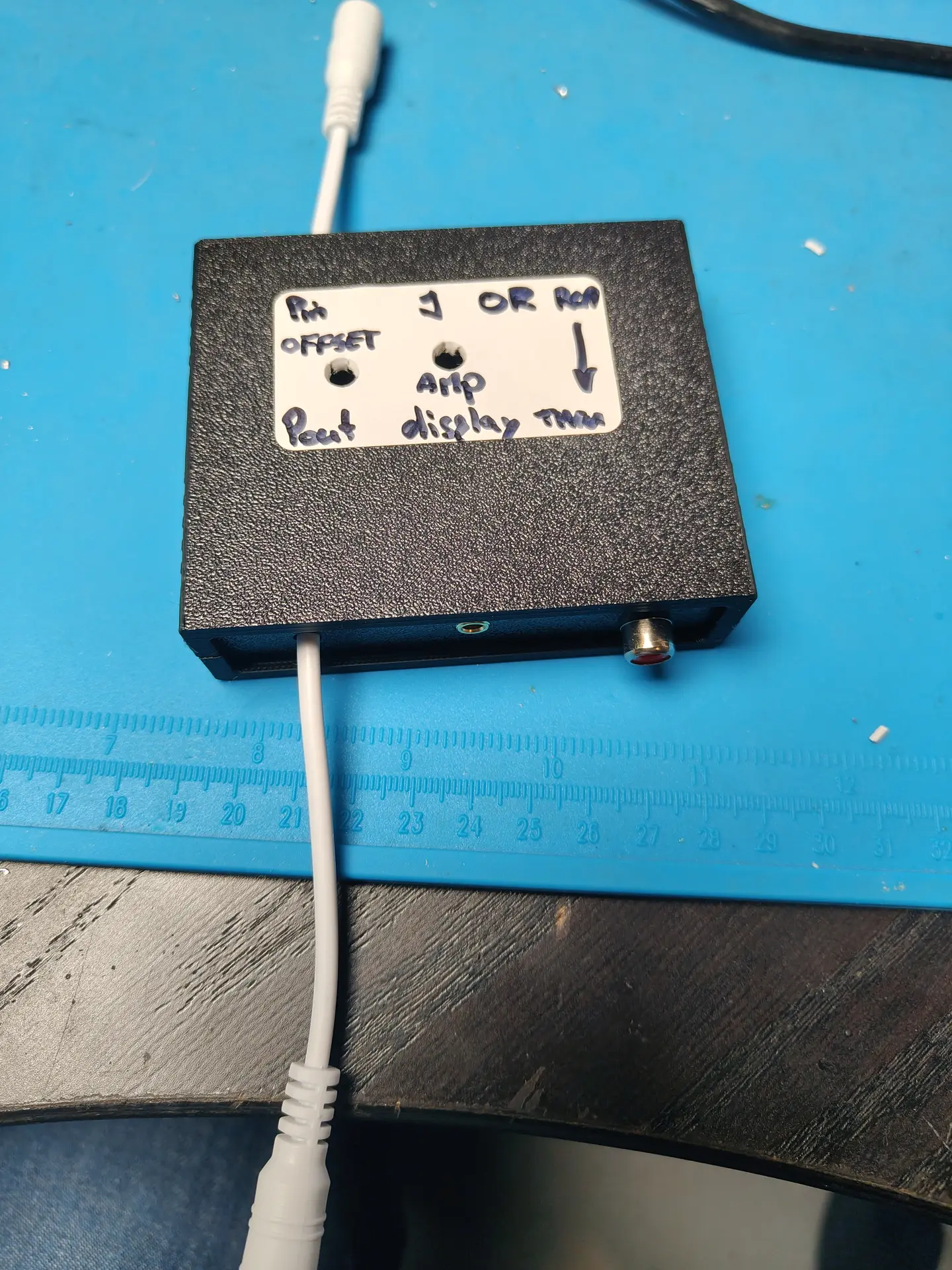
A = Audio input
B = Setting the offset with P1
C = Setting the amplification
Below input signal (note negative values) above amplified signal with offset!
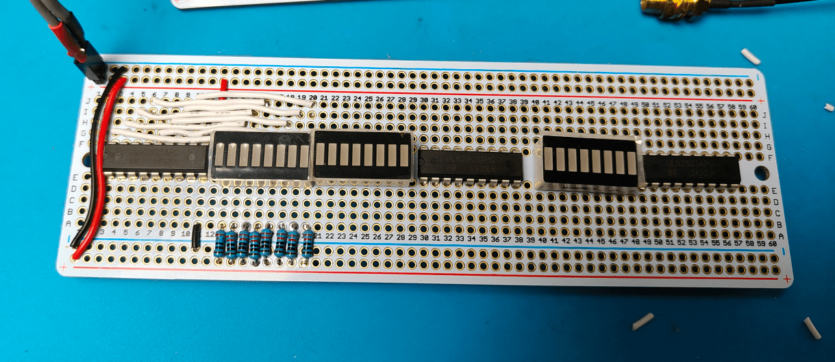
The displays are 3 Wemos controllers with a cheap I2C display. These are just fast enough to do FFT.
Analogue in is the output from the OP-amp offsetter ..
CODE
Needs cleaning up, and a better stabilize routine.
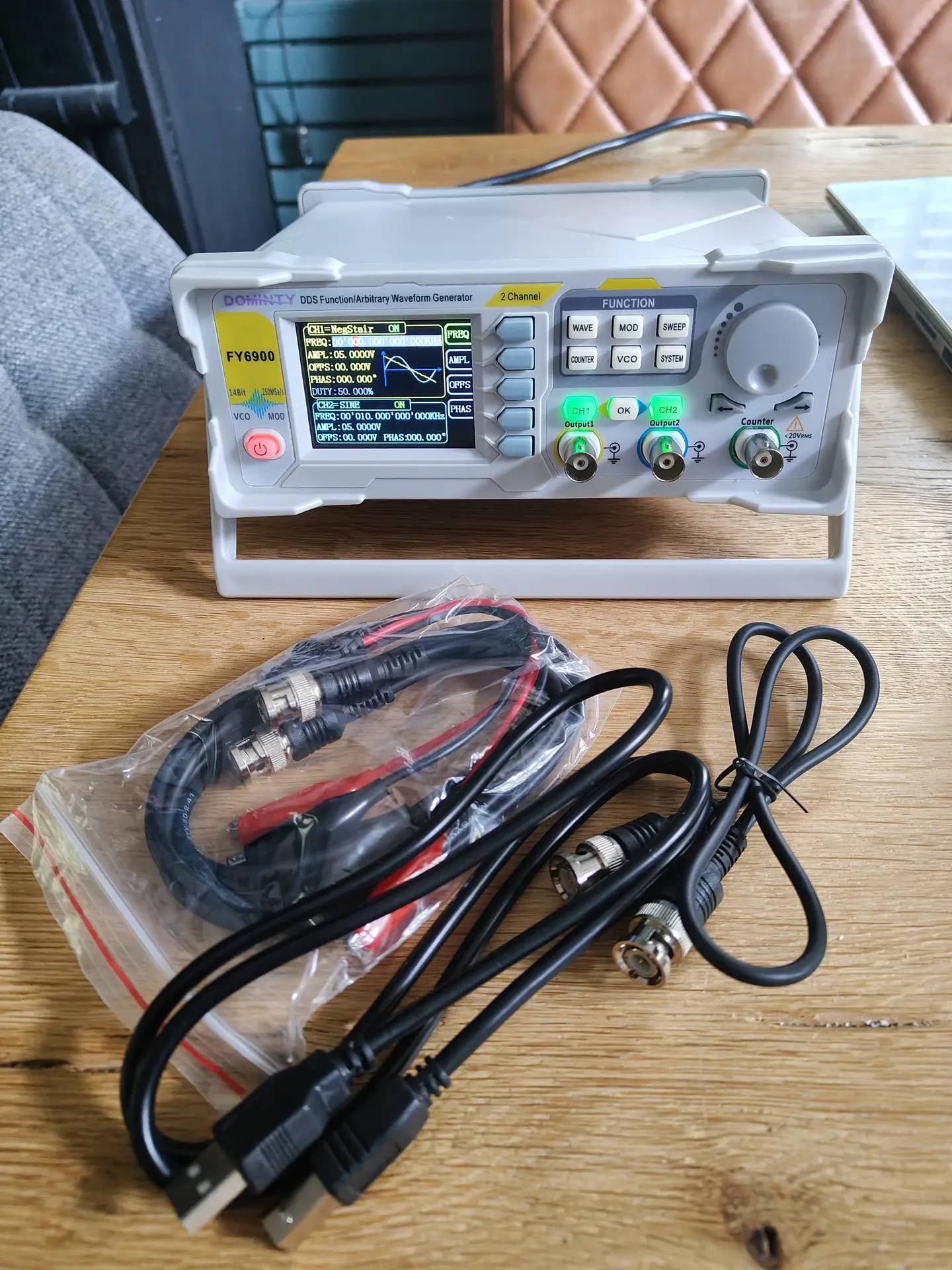
Yesterday I got my new signal generator (FY6900), my DIY version was missing functions. Now I can test my op-amp schematic I’ve been posting about.
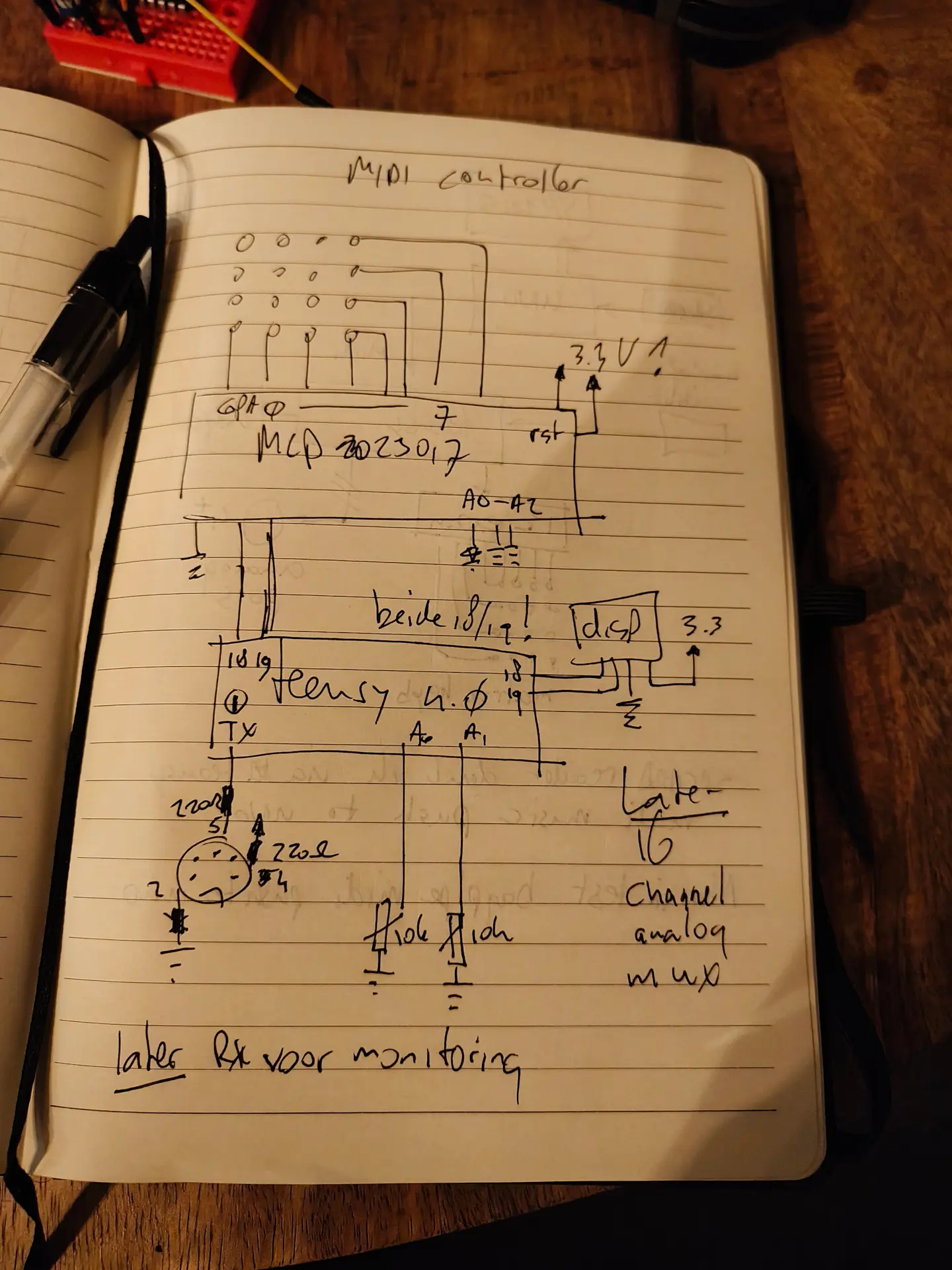
MIDI Controller
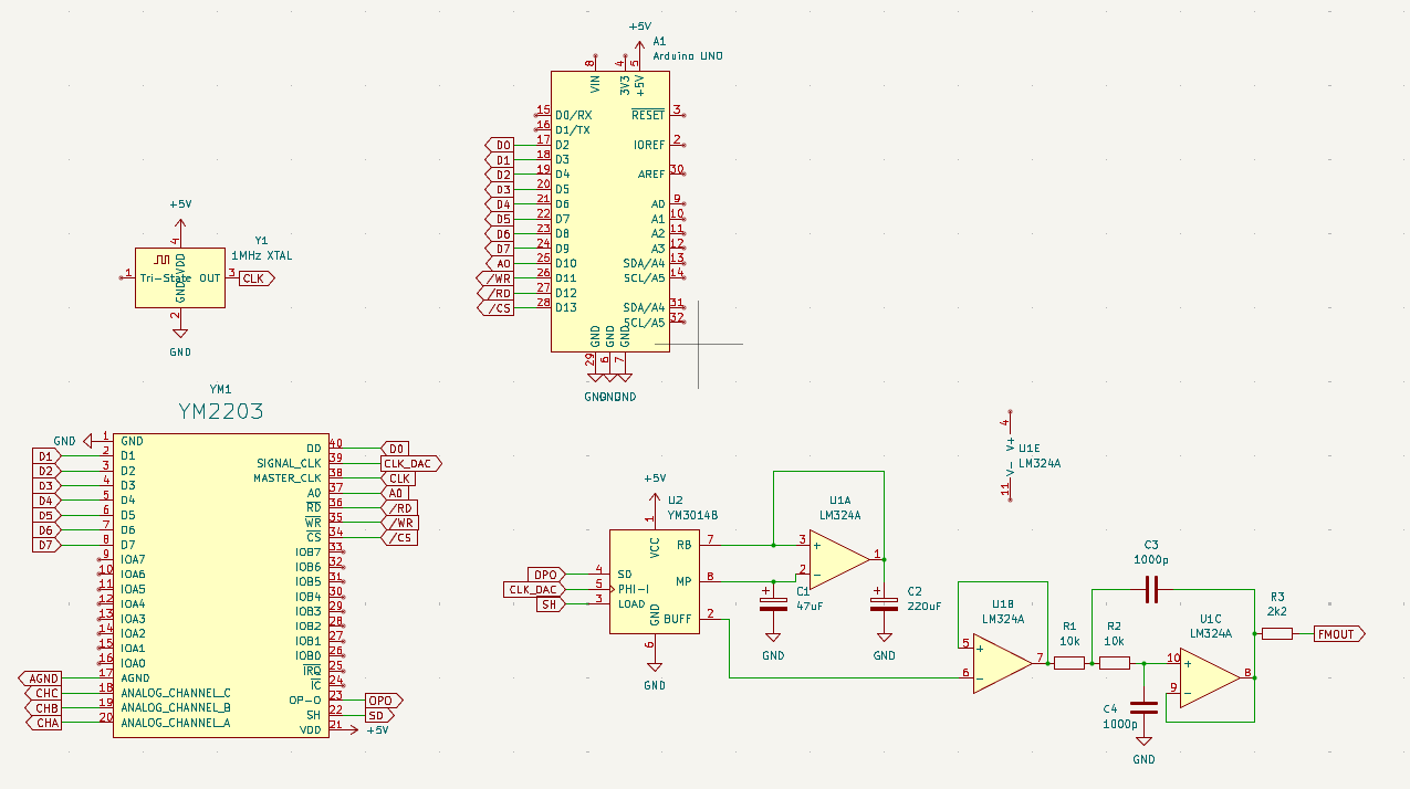
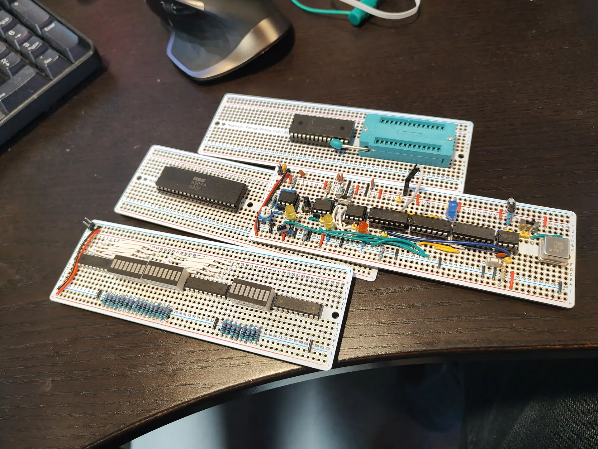
Next, for my YM2203 player, I wanted to make this Midi Controllable. But I don’t have a Midi Controller which has enough knobs and keys. Besides that, I thought it was cool to build my own.
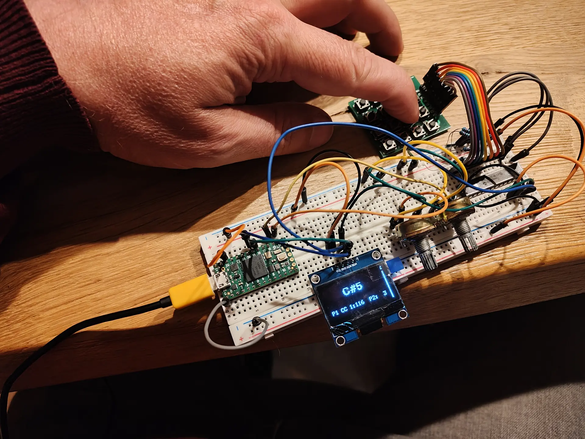
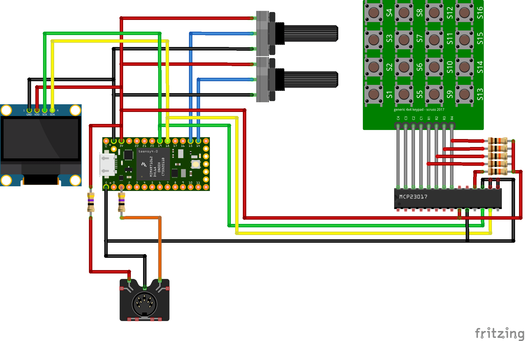
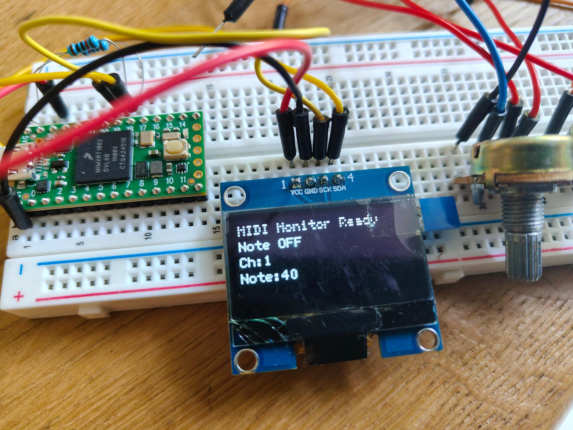
Teensy 4.0 (because I needed multiple analogue inputs, I used another controller before, with an analogue multiplexer. But I wanted to use the easy method to use USB as midi also. The board will also have midi connectors, but not populated yet. So you can use both.
SSD1306 display (for now) Showing note being played and two potentiometer values.
Two potentiometers (for now) I can use these separately. But when pressing the last key on the key matrix, it will change the CC Channel of the first pot. (Using the value of the second)
4×4 Matrix keyboard being read by a MCP23017 I2C 16-bit GPIO Expander. Both display and GPIO expander are on the same bus.
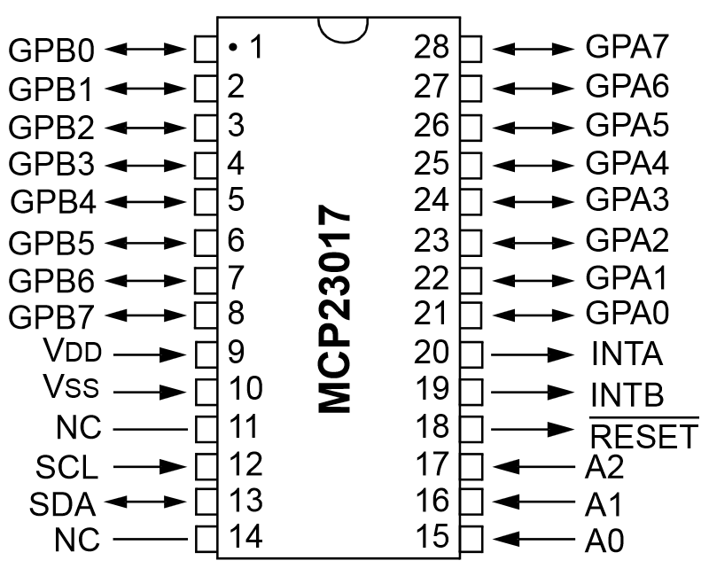
MCP23017 pinout
I used some pullups on : /RESET and GPA0-3 Pullups not needed on SDA/CLK because these are on the display board.
Damn, I couldn’t do this stuff in school. Tried to forget it all … now I need it!
Top of this image shows what I want to accomplish. Audio or other input which has negative values also, convert to another voltage range to be read by analog read on an Wemos. These can only read 0-3v3
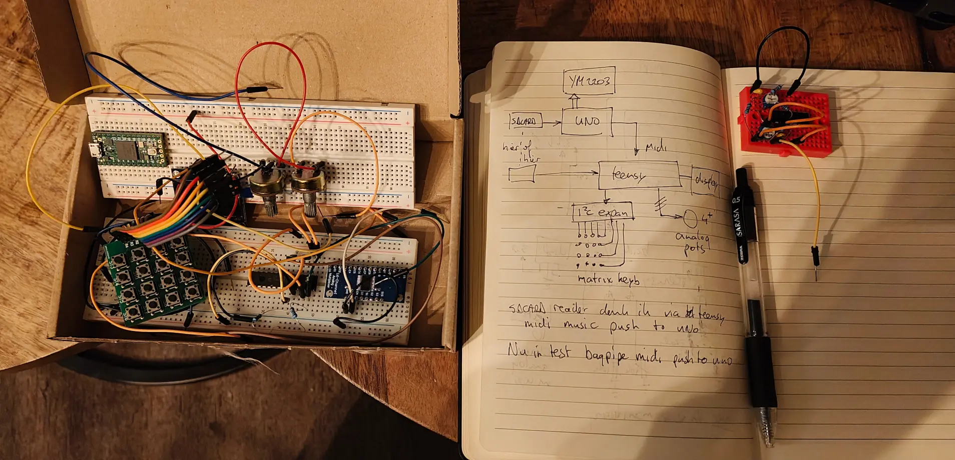
I took yesterday’s setup and added polyphonic Midi.
Schematic same as previous post, just added a Midi Shield.
I can use my QY100 as midi keyboard. But playing midi files is also fun!
Because it isn’t using the right instrument and not all channels are being used.
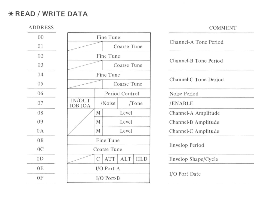
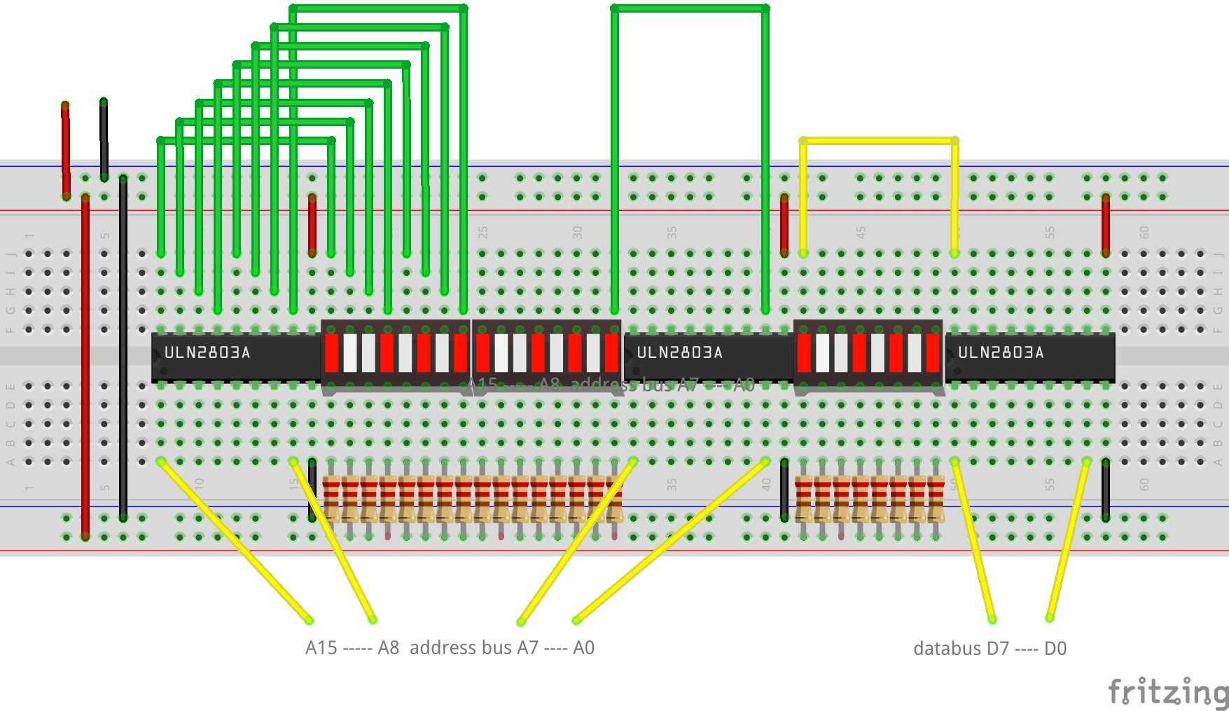
I wanted to make a register replacer, which utilizes a sdcard reader and music dump to play songs. But I think I’m going to make a full-blown Midi song player for the YM2203.
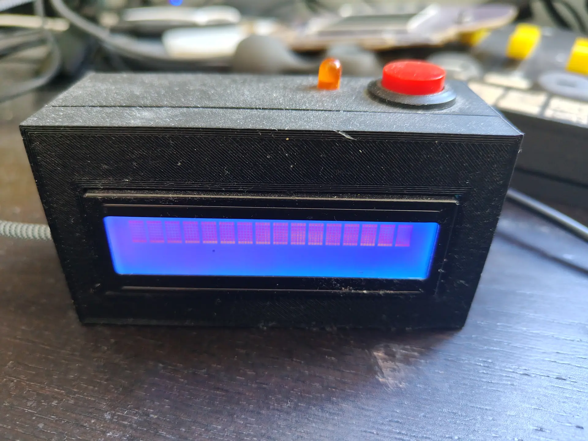
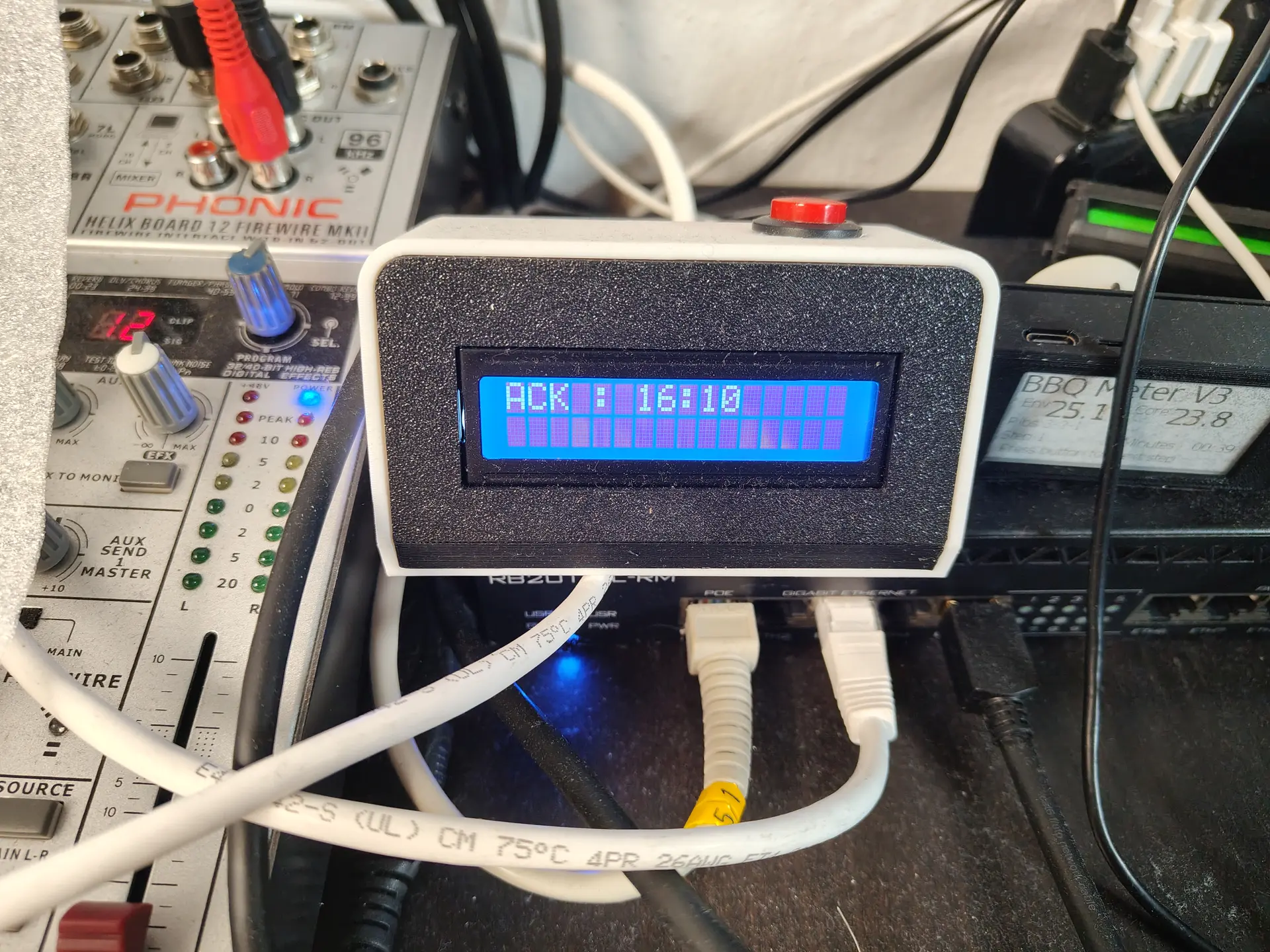
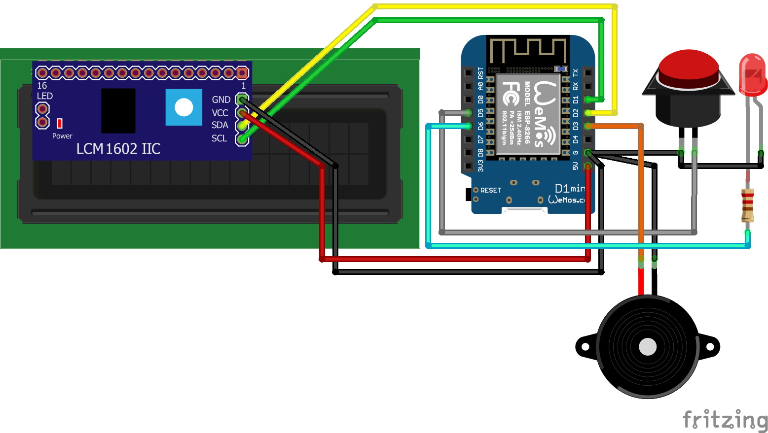
A while ago I made a little notify thingy using an LCD display, LED, button and a buzzer.
V1V2
Some friends of mine made one also, and today I was talking to a new guy. I could not find this project on my site .. again .. so I’ll post it now.
Some things it does right now
Front door opens
Door bell rings (because my lab is in the garden)
Girlfriend is 10Km away, so let’s start cooking
Garage door opens (friend of mine uses this to know when kids arrive)
More .. because it’s very easy to customize in Home Assistant
Doorbell pressed: Led starts blinking, backlight LCD enabled, text displayed on LCD, Buzzer sounds (or plays a RTTTL ringtone) LCD backlight on and buzzer beep until acknowledge button pressed.
Heating for brewing: temperature on display, led on when temperature reached. Press acknowledge to start timer.
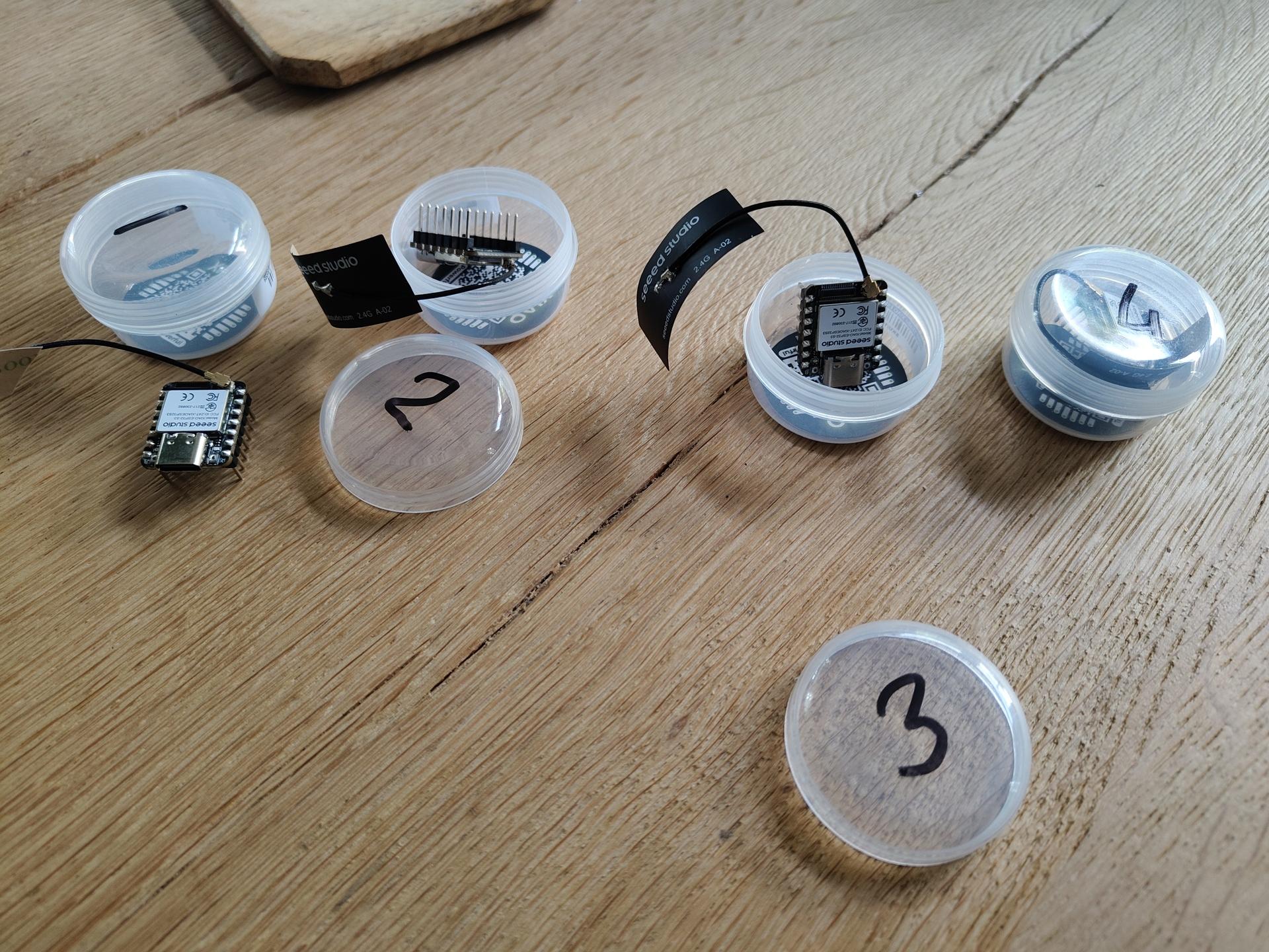
I bought 4x Xiao-S3 mini controllers. I want to place these all over my house to scan for Bluetooth and Wifi Clients. So I can do a location search for Mobile Phones, Keys and more.
Also the Bluetooth tags I used for the Scanner Game can be used!
I want to post a location to Home Assistant, But I also played with 3D view.
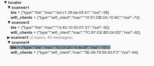
Using MQTT I can subscribe to the topic locator/scanner1/ble or locator/scanner1/wifi_clients
Problems I ran into.
Too many duplicates, fixed. Can not scan Wifi when connected, so I connect every 30s. Could not find all wifi clients, needed to scan all channels!